Page is loading ...

INSTALLATION
KHM 525 PS/PSX M
2-7
10/10/07 78515-GB
SUPER
SILENCED
KHM 525 PSX
SUPER
SILENCED

REMOTE CONTROL PHG1B-PHG1B/PL KHM
M
38.8
16/01/08 M38GB
PUSH AND
SCREW TIGHT
ONLY PL
VERSION
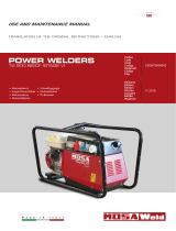
When the PHG1B is not used, it is necessary to disconnect
the multipole connector
ATTENTION
The remote control PHG1B, which regulates the welding
current in the CC (STICK welding) mode and the welding
voltage in the CV (MIG/MAG welding) mode, is connected to
the front panel by means of a multipole connector.
When the remote control is connected to the remote control
connector (8), it is functional and automatically excludes the
front panel regulation. The remote control can also be
connected to the connector on the wire feeder front panel but
in this case it is necessary to switch the wire feeder commutator
so it can operate.
The polarity inverter (64A), if installed, can be operated from
the remote control.
Adjust the welding current control knob to the correct current
for the diameter and type of electrode being welded.

DECLARATION OF CONFORMITY
according to the Machinery Directive 98/37/EC, the Low Voltage Directive 2006/95/EC,
the EMC Directive 2004/108/EC and the Directive 2000/14/EC
Type of equipment
Engine driven welding generator
Brand name or trade mark
ESAB
Type designation etc.
KHM 525 PS, Part No. 0794 021-880 /-881 /-882 /-883
Electrical power : 15 kW
Measured acoustic power level LwA 93 dB(A), Guaranteed acoustic power level LwA 94 dB(A)
KHM 525 PSX, Part No. 0794 021-890 /-891 /-892 /-893
Electrical power : 15 kW
Measured acoustic power level LwA 92 dB(A), Guaranteed acoustic power level LwA 93 dB(A)
Manufacturer or his authorised representative established within the EEA
Name, address, telephone No, telefax No:
ESAB AB, Welding Equipment
Esabvägen, SE-695 81 LAXÅ, Sweden
Phone: +46 584 81 000, Fax: +46 584 411 924
The following harmonised standard in force within the EEA has been used in the design:
EN 60974-1, Arc welding equipment – Part 1: Welding power sources
EN 12100-1, Safety of machinery – Basic concepts and general principles for design – Part 1: Basic
terminology
EN 12100-2, Safety of machinery – Basic concepts and general principles for design – Part 2: Technical
principles
EN 60204-1, Safety of machinery – Electrical equipment of machines – Part 1: General requirements
EN 60974-10, Arc welding equipment – Part 10: Electromagnetic compatibility (EMC) requirements
EN 50081-2, Electromagnetic compatibility – Generic emission standard – Part 2: Industrial environment
EN 50082-2, Electromagnetic compatibility – Generic immunity standard – Part 2: Industrial environment
By signing this document, the undersigned declares as manufacturer, or the manufacturer’s
authorised representative established within the EEA, that the equipment in question complies
with the safety requirements stated above.
Date Signature Position
Laxå 2008-03-10 Global Director
Equipment and Automation
Kent Eimbrodt
Clarification

Index
KHM 525 PS/PSX M
1
10/10/07 78515-GB
Dear Customer,
We wish to thank you for having bought this product.
Please take time to read this manual and familiarize yourself with the machine before attempting to use it.
If you should have questions or problems please contact the nearest authorized Service Center. They
have the experience and original spare parts. The use of non-original spare parts will void the warranty.
TABLE OF CONTENTS
DESCRIPTION PAGE
GENERAL INFORMATION
INFORMATION ABOUT THIS MANUAL M 2
DESCRIPTION - SYMBOLS M 2.1
PRECAUTIONS - GENERAL M 2.5
PRECAUTIONS - ENGINE DRIVEN WELDERS M 2.5.1
TRANSPORT M 4
ASSEMBLY OF SITE TOW FOR KHM 525 M 6.3
INSTALLATION INFORMATION M 2.6
INSTALLATION M 2.7
OPERATION
UNPACKING M 3
TECHNICAL DATA AND MACHINE DESCRIPTION M 1.5, M 1.6
PREPARING THE UNIT M 20
STARTING THE ENGINE M 21
STOPPING THE ENGINE M 22
CONTROLS M 31
OPERATING M 32
USE - WELDING DIGITAL CONTROL M 33, 33.1, 33.2
REMOTE CONTROL PHG1B M 38.8
MAINTENANCE M 43, M 43.3
STORAGE M 45
TECHNICAL DATA M 53
SCHEMATICS AND SPARE PARTS
WIRING DIAGRAM – ENGINE M 61.1
WIRING DIAGRAM – AUXILIARY Y400V / 3 x I230V M 61.2
WIRING DIAGRAM – WELDING POWER M 61.3
WIRING DIAGRAM – WELDING CONTROL M 61.4

INFO KHM
M
2
07/01/08 M2GB
GENERAL INFORMATION
− In the envelope where you found this manual you will also
find an Owner’s manual for the engine, and accessories (if
required).
This product has been designed for welding and generation
of electrical power for tools and other electrical devices used
in construction; ANY OTHER USE, is not permitted and we
cannot be held responsible for injuries or damages resulting
from such incorrect use.
Our products are made in conformity with the safety norms in
force in order to avoid injury to persons or damage to the
machine or other things.
☞
Warranty is not valid if not carried out by ESAB
authorized service agent.
Making modifications to the machine without our written
authorization will void the warranty and release us from any
liability.
ABOUT THIS MANUAL
Before using the machine please read this manual attentively
and follow the instructions contained in it. This will help avoid
problems, possible injury and damage to the machine.
The manual is written for experienced, qualified personnel,
who are familiar with health and safety laws and related
regulations.
This manual is an integral part of the product and should be
kept in a safe place so that it will be available for consultation
during the life of the product. If the machine is sold the manual
should be transferred to the new owner.
Some figures contained in this manual are designed to help
identify certain parts and may not correspond to the machine
in your possession.
☞
Notice: the manufacturer may make improvements or
modifications to the product or its accessories as described
in this manual without updating the manual.
ATTENTION
NOTE
IMPORTANT
CAUTION
WARNING
DANGEROUS
HEADINGS USED IN THIS MANUAL
The headings used in this manual are designed to call your
attention to potential hazards and important aspects of the
operation of the machine…
lndìcates a strong possíbility of severe personal injury or
death ìf ínstructions are not followed.
lndìcates a possibìlìty of personal ínjury or equipment damage
if ìnstructions are not followed
lndícates that equipment or property damage can result if
instructions are not followed.
These headings give helpful information about the
preparation, operation and care of the machine.

SYMBOLS KHM
M
2.1
GENERAL SYMBOLS
STOP – Read with great attention
Read with attention
WRENCH - Use the correct tools for the type of
work being done
WARNING SYMBOLS
ATTENTION - If this advice is not followed people
or things can be hurt or damaged.
HIGH VOLTAGE - Do not touch – risk of injury or
death.
FIRE - Risk of fire.
HEAT - Hot surfaces.
EXPLOSIVE - Explosive material or danger of
explosion, in general.
NO WATER - Do not use water as it can cause
shortcircuits or other damage.
NO SMOKING - Cigarettes, matches or lighters
can start a fire or explosion.
ACIDS - Danger of corrosion or burns.
SAFETY SYMBOLS
Use the correct protective devices for the type of welding
being done
Use protective clothing, etc. specifically
designed for the type of welding being done.
Protect yourself when doing maintenance on the machine
-
It is advisable to protect yourself when carrying
out maintenance, such as filling the battery,
refuelling, etc.
Pay attention to safety precautions when moving the
machine
Refer to the instructions before moving the
machine
Wear indicated safety clothing -
It is compulsory to wear the personal
protection items shown when using the
equipment.
Use required safety devices -
Safety devices suitable for the type of welding
and the location of the job must be used.
Do not use water on electrical fires -
It is prohibited to use water to put our fires in
electrical equipment.
Do not touch without having disconnected the electricity -
It is prohibited to work on the machine until the
electricity has been turned off.
Welding prohibited -
It is forbidden to weld in areas containing
explosive gases.

IMPORTANT
☞
Read and understand these instructions.
☞
Before installing, operating or servicing this
equipment, read the operating manuals of the welder
and of the engine.
☞
Not observing the information in the manuals can
result in personal injury and/or damage to the
equipment and other property.
☞
Respect all safety regulations and laws when operting
this equipment.
WARNING
Do not remove or disable protective devices
Removing or disabling protective devices on the machine is
prohibited.
Do not use the machine if it is not in good technical
condition
The machine must be in good working order before being
used. Defects, especially those which. regard the safety of
the machine, must be repaired before using the machine.
ENGINE FUELLING
⇒ Stop engine when fuelling.
⇒ Do not smoke, avoid open flames and sparks, and do not
use electric tools when fueling.
⇒ Unscrew the fuel cap slowly to let out the fuel vapours.
⇒ Do not over-fill the tank.
⇒ Avoid spilling fuel on hot engine.
⇒ Wipe up spilled fuel before starting engine.
⇒ Shut off fuel cock, if present, or remove fuel from tank
before moving machine
FOR BATTERY EQUIPPED UNITS ONLY
⇒ Sparks may cause the explosion of battery vapours
WATER COOLED ENGINES ONLY
⇒ Slowly unscrew the cooling liquid cap of a hot engine to
allow vapours to escape.
⇒ Hot vapor and heated cooling liquid under pressure can
burn face, eyes, skin.
INSTALLATION AND ADVICE BEFORE USE KHM
☞
FIRST AID. In case the operator shold be sprayed by accident, from corrosive liquids a/o hot toxic gas
or whatever event which may cause serious injuries or death, predispose the first aid in accordance with the
ruling labour accident standards or of local instructions.
Skin contact
Eyes contact
Ingestion
Suction of liquids from
lungs
Inhalation
Wash with water and soap
Irrigate with plenty of water, if the irritation persists contact a specialist
Do not induce vomit as to avoid the intake of vomit into the lungs, send for a doctor
If you suppose that vomit has entered the lungs (as in case of spontaneous vomit) take the
subject to the hospital with the utmost urgency
In case of exposure to high concentration of vapours take immediately to a non polluted zone
the person involved
☞
FIRE PREVENTION. In case the working zone,for whatsoever cause goes on fire with flames liable to
cause severe wounds or death, follow the first aid as described by the ruling norms or local ones.
Appropriated
Not to be used
Other indications
Particular protection
Useful warnings
Carbonate anhydride (or carbon dioxyde) powder, foam, nebulized water
Avoid the use of water jets
Cover eventual shedding not on fire with foam or sand, use water jets to cool off the
surfaces close to the fire
Wear an autorespiratory mask when heavy smoke is present
Avoid, by appropriate means to have oil sprays over metallic hot surfaces or over electric
contacts (switches,plugs,etc.). In case of oil sprinkling from pressure circuits, keep in
mind that the inflamability point is very low.
EXTINCTION MEANS
WARNING CAUTION
WARNING
THE MACHINE MUST NOT BE USED IN AREAS WITH
EXPLOSIVE ATMOSPHERE
M
2.5
06/03/00 M2.5GB

PRECAUTION (ENGINE DRIVEN WELDER) KHM
M
2.5.1
PRECAUTIONS
The operator of the welder is responsible for the security of the people who work with the welder and for those in the vicinity.
The security measures must satisfy the rules and regulations for engine driven welders.
The information given below is in addition to the local security norms.
ATTENTION
➠
Make sure that the area is safe before starting any welding
operation.
➠
Do not touch any bare wires, leads or contacts as they
may be live and there is danger of electric shock which
can cause death or serious burns. The electrode and
welding cables, etc. are live when the unit is operating.
➠
Do not touch any electrical parts or the electrode while
standing in water or with wet hands, feet or clothes.
➠
Insulate yourself from the work surface while welding.
Use carpets or other insulating materials to avoid physical
contact with the work surface and the floor.
➠
Always wear dry, insulating gloves, without holes, and
body protection.
➠
Do not wind cables around the body.
➠
Use ear protections if the noise level is high.
➠
Keep flamable material away from the welding area.
➠
Do not weld on containers which contain flamable
material.
➠
Do not weld near refuellng areas.
➠
Do not weld on easily flamable surfaces.
➠
Do not use the welder to defrost (thaw) pipes.
➠
Remove the electrode from the electrode holder, when
not welding.
➠
Avoid inhaling fumes by providing a ventilation system
or, if not possible, use an approved air breather.
➠
Do not work in closed areas where there is no fresh air
flow.
➠
Protect face and eyes (protective mask with suitable dark
lens and side screens), ears and body (non-flamable
protective clothes).
19/06/00 M2.5.1GB

TRANSPORT KHM
M
4
DANGEROUS
In case you have to move or transport or move the machine, follow the instructions as shown in the figures.
Transport the machine ithout petrol in the tank, ithout oil in the engine and ithout electrolyte in the battery. Be sure that
the transportation devices are adequate for the size and weight of the machine.
DO NOT TRANSPORT ACCESSORIES OR OTHER ITEMS WHICH COULD INCREASE THE WEIGHT AND/OR CHANGE
THE CENTER OF GRAVITY OF THE MACHINE.
DO NOT DRAG THE MACHINE OR TOW IT ON PUBLIC ROADS UNLESS IT IS MOUNTED ON A HOMOLOGATED
TRAILER.
Not following these instructions could cause injury or damage to the machine.
"CTL" SITE TOW
The machines provided for assembling the CTL accessory (slow towing trolley) can be towed up to a ma imum speed of
ms hour on asphalted surfaces.
☞
Towing on public roads or turnpikes of any type IS EXCLUDED, because not in possesion of the requirements by
national and foreign traffic norms.
DANGER LIFTING EYE IS NOT DESIGNED TO SUPPORT
ADDED WEIGHT OF ROAD TOW TRAILER
DO NOT LIFT THE MACHINE AND TRAILER
LIFT ONLY THE MACHINE

ASSEMBLY OF SITE TOW FOR KHM 525
M
6.3
Nota
: Lift the machine and assemble the parts as shown in the drawing
The accessory cannot be removed from the machine and used separately (actioned manually or following vehicles) for the
transport of loads or anyway for used different from the machine movements.
For assembling the generating set on the trolley please keep
to following instructions:
1) - Lift the generating set (by means of suitable hook).
6) - Assemble on the machine the towbar (5) complete of
foot with the M10x20 screws, nuts and washers.
7) - Assemble the axle (7) to the base of the machine (see
fig. page M6.3) with the M10x25 screws and relative
washers (two per part) so that their supports coincide.
8) - Insert the wheel (9) on the axle then screw the self
blocking nuts (8).
9) - Pump the tyre (9) bringing the pressure to four atms.
10) - Lower the machine to the ground and place the parking
foot definitively (regulating at the best height).
ATTENTION
Do not substitute the original tires with other types.
ATTENTION
7
8
9
TRAILERS
The machines provided for assembling the accessory (slow towing trolley) can be towed up to a maximum speed of 40 Kms
hour on asphalted surfaces.
Towing on public roads or turnpikes of any type
IS EXCLUDED, because not in possesion of the requirements by national and
foreign traffic norms.
16/01/08 M06GB

PRECAUTION (ENGINE DRIVEN WELDER) KHM
M
2.6
1,5 m
1,5 m
1,5 m
GAS DI SCARICO
DIESEL ENGINES
· Use in open space with fresh air flow or vent exhaust
gases far from the work area.
POSITIONING T E MAC INE
Place the machine on a level surface at a distance of at least
1,5 m from buildings or other structures.
If the surface is not level be sure that the angle of the machine
does not exceed the values shown in the drawings below.
MOVES OF T E MAC INE
☞
At any move check that the engine is off, that there
are no connections with cables which impede the
moves.
PLACE OF T E MAC INE
ATTENTION
For a safer use from the operator DO NOT
fit the machine in locations with high risk of
flood.
Please do not use the machine in weather
conditions which are beyond IP protection
shown both in the data plate and on page
named "technical data" in this same manual.
☞
Assure that the hot air and/or exhaust gas from the
machine are vented and are not recirculated in the machine.
Hot air and/or exhaust gas which is recirculated wll cause
overheating of the machine and poor combustion in the engine
☞
Make sure that the machine does not move during
operation.
20/06/00 M2.6GB

INSTALLATION
KHM 525 PS/PSX M
2-7
10/10/07 78515-GB
SUPER
SILENCED
KHM 525 PSX
SUPER
SILENCED

UNPACKING KHM
M
3
GENERAL PACKING INFORMATION
2
B
A
1
C
Upon receipt of the goods make sure that the product has not
been damaged during transport.
In case of damage or missing items you must inform your
freight forwarder immediately.
acking materials must be disposed of according
to local regulations.
UNPACKING THE MACHINE
ake the machine out of the carton. ocate the User s
anual , which is packed together with the engine manual
and accessories in a plastic envelope . his envelope
may be under or inside the machine.
heck the rating plate on the machine and confirm that the
serial number and model are the same as shown on the
packing note invoice.
NB.: or further information on preparing the unit for use refer
to the related parts of this manual.
ES

TECHNICAL DATA
KHM 525 PS M
1.5
The KHM 525 engine driven welder ia a unit which ensures the function as:
a) a current source for arc welding
b) a current source for the auxiliary power generation
It is meant for industrial and professional use, powered by an endothermic engine; it is composed of
various main parts such as: engine, alternator, electric and electronic controls, the fairing or a protective
structure.
The assembling is made on a steel structure, on which are provided elastic support which must damp the
vibrations and also eliminate sounds which would produce noise.
Technical data KHM 525 PS
GENERATOR
Output three-phase 16 kVA / 400 V / 23.1 A
Output single-phase 12 kVA / 230 V / 52.1 A
Frequency 50 Hz
Cos
ϕϕ
ϕϕ
ϕ 0.8
ALTERNATOR Self-excited, self-regulated, brushless
Type three-phase, asynchronous
Insulating class H
ENGINE
Mark / Model PERKINS / 404C-22G
Type / Cooling system 4-Stroke / Liquid
Cylinders / Displacement 4 / 2216 cm
3
Output max 20.3 kW (27.6 HP)
Speed 1500 rpm
Fuel / Fuel consumption (P.R.P.) Diesel / 243 g/kWh
Cooling system capacity 10.2 l
Engine oil capacity 8.5 l
Starter Electric
GENERAL SPECIFICATIONS
Tank capacity 60 l
Running time 14 h
Protection IP 23
Dimensions Lxwxh (mm) * 1720x980x1110
Weight * 750 Kg
Measured acoustic power 95 LWA (70 dB(A) - 7m)
Guaranteed acoustic power 96 LWA (71 dB(A) - 7m)
* Dimensions and weight are inclusive of all parts without wheels and towbar.
10/10/07 78514-GB
POWER
Declared power according to ISO 3046-1 (temperature 25°C, 30% relative humidity, altitude 100 m above sea level).
It’s admitted overload of 10% each hour every 12 h.
In an approximative way one reduces: of 1% every 100 m altitude and of 2.5% for every 5°C above 25°C.
ACOUSTIC POWER LEVEL
ATTENTION: The concrete risk due to the machine depends on the conditions in which it is used. Therefore, it is up
to the end-user and under his direct responsibility to make a correct evaluation of the same risk and to adopt
specific precautions (for instance, adopting a I.P.D. -Individual Protection Device)
Acoustic Noise Level (LWA) - Measure Unit dB(A): it stands for acoustic noise released in a certain delay of time.
This is not submitted to the distance of measurement.
Acoustic Pressure (Lp) - Measure Unit dB(A): it measures the pressure originated by sound waves emission. Its
value changes in proportion to the distance of measurement.
The here below table shows examples of acoustic pressure (Lp) at different distances from a machine with Acoustic
Noise Level (LWA) of 95 dB(A)
Lp a 1 meter = 95 dB(A) - 8 dB(A) = 87 dB(A) Lp a 7 meters = 95 dB(A) - 25 dB(A) = 70 dB(A)
Lp a 4 meters = 95 dB(A) - 20 dB(A) = 75 dB(A) Lp a 10 meters = 95 dB(A) - 28 dB(A) = 67 dB(A)
PLEASE NOTE: the symbol when with acoustic noise values, indicates that the device respects noise
emission limits according to 2000/14/CE directive.
2000/14/CE
2000/14/CE

TECHNICAL DATA
KHM 525 PS/PSX
M
1.6
C.C. WELDING
Welding current 500A -35%, 450A -60%, 400A -100%
Starting voltage 62V
C.V. WELDING
Welding current 450A-60%; 400A-100%
Welding voltage 16 - 40V
SIMULTANEOUS UTILI ATION ACTORS
In case Weldin and eneration can be used simultaneously, however, the engine
cannot be overloaded.
The table below gives the maximum limits to be respected:
AU ILIAR POWER
WEL IN CURRENT
10/10/07 78515-GB
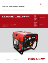
STATIC CHARACTERISTIC
100 200
300 400 500
A
V
10
20
30
40
50
60
65
10
min.
max
C.V.
TIG
C.C.
C.C.
C.C.
2 VA VA VA
A A5A
5 A
VA

PREPARING THE UNIT (DIESEL ENGINES) KHM
M
20
ES
BATTE ITH UT MAINTENANCE
onnect the cable positive
to the pole positive of the
battery after having taken
away the protection , by
properly tightening the clamp.
heck the state of the battery
from the colour of the warning light which is in the
upper part.
reen colour battery
lack colour battery to be recharged
hite colour battery to be replaced
N T PEN THE BATTE .
UB ICANT
LIVELLO
OPERATIVO
ASTINA LIVELLO
OLIO
MAX
MIN
heck the level of the engine oil using the
oil dipstick. he level should be between
the minimum and maximum marks. lf
necessary, add more oil.
If the air filter is of the oil bath type, fill it with the
same oil up to the level indicated on the filter.
EC MMEN E AE I C IT G A E
or the type and viscosity of oil refer to owner s
manual for the engine supplied with the machine .
NOTE: Before starting the engine read the instructions
in the owner’s manual for the engine.
UE
ill the tank with good quality diesel fuel.
☞ ATTENTI N Diesel fuel is highly
inflammable before filling the tank, stop the
engine. Do not fuel in the presence of open
flames.
If fuel is spilled on the engine, clean it
immediately before starting up the engine.
C ING I UI
our the cooling liquid through the hole at the
top of the radiator until it reaches the opening. or
the type of cooling liquid to be used and for
maintenance of the cooling system, refer to the
engine manual.
G UN C NNECTI N
good ground is obligatory for all models with I
ground fault interrupter E earth leakage
circuit breaker . hese protective devices will not
protect the operator unless there is a good ground.
☞ Use a good quality ground cable and connect it
to the grounding point of the machine .
ollow all local rules and or regulations in force.
achines with Isometer protection do not need to
be grounded.
nce the above operations have been completed,
the machine can be used.

M
21
Do not alter the factory adjustment of the engine
and do not touch the sealed parts.
Check daily
RUNNING-IN
During the first 50 hours of operation, do not use
more than 60% of the maximum output power of
the unit and check the oil level frequently, in any
case please stick to the rules given in the engine
use manual.
CAUTION
KHM 525 PS/PSX
10/10/07 78515-GB
STARTING THE ENGINE
NOTE
Temperature Time
≤ - 20° C
to - 20° C from -10°C
to - 10° C from -5°C
≥ 5° C
5 min.
2 min.
1 min.
20 sec.
ATTENTION
1. By start-up of the generator the welding circuit is
immediately operative, i.e. under voltage. Make
sure that there are no unwished electrical
contacts between the components of the outside
welding circuit (electrode, electrode holder gun,
workpiece, etc…).
2. Check that at the start-up the a.c. auxiliary
generation sockets do not feed any load.
Open the GFI (D) of the generator or
disconnect the plugs of the loads from
the sockets.
3. STARTING
Starting is actuated using the key which is an integral
part of the EP7 post on the front panel.
A) - Turn the key in a clockwise direction until all
the LED lights are illuminated.
B) - Wait until the “OIL PRESSURE” and
“BATTERY VOLTAGE” LEDs remain
illuminated. If the timer lamp is used, the yellow
“PREHEAT” LED comes on for the set time of
the imposed settings.
C) - As soon as the green “ENGINE RUNNING”
LED starts to flash, actuate the key switch in a
clockwise direction (momentarily in the position
then with return to rest) until obtaining starting
of the engine.
If the motor does not start within 15 seconds,
the non starting alert will intervene: the two
LEDs “Engine running” and “glow plug” will
flash alternately (see motor protection
description).
D) - At any time it is possible to stop the engine by
turning the key in an anti-clockwise direction
(OFF position).
In case of engine anomaly due to low oil
pressure, high temperature, broken
transmission belt, low fuel level or emergency
the EP7 will automatically stop the engine.
4. the motor starts up at its operating speed, 1500
or 1800 rpm. After start-up, allow the motor to
run for a few minutes before powering on the
utilities. See table;
5. start-up at low temperatures.
The motor will normally start up without problems
down to temperatures of -10° C, -15° C. In case
of starting difficulty, it is possible to repeat the
starting preheating for a max. time of 10 second,
lightly turning the trimmer situated at the back of
the EP7 in a clockwise direction (see page M32.2
relating to engine protection “trimmer/glow plug”).
For start-up and use at lower temperatures please
see the engine manual or turn to our Technical
Assistance Center.
In case of unsuccessful start-up, do not
insist for longer than 5 seconds. Wait 10 -
15 seconds before attempting another start-
up.
NB.: for safety reason the key must be kept by
qualified personel.

M
22
KHM 525 PS/PSX
10/10/07 78515-GB
STOPPING THE ENGINE
STOP
For shutdown under normal conditions, proceed as
follows:
Break the welding process in course.
2 Break the production of a.c. auxiliary generation
dividing the loads or opening the GFI
(D).
Let the engine run with no load for a few minutes.
Turn the start key on the EP7 to the OFF position.
EMER ENC SHUT OWN
To stop the group in a dangerous situation, press
the emergency stop button (L5) (or turn the start
key (Q1) to the OFF position). To reset the knob,
turn it clockwise.
OFF
ON
START

CONTROLS
KHM 525 PS M
31
os. Description Descriptionos.
Description Description
9
10
12
15
22
23
24B
25
26
27
31
31C
59A
59B
59C
C2
Welding socket ( + )
Welding socket ( - )
Earth terminal
A.C. socket
Engine air filter
Oil level dipstick
Water filling cap
Fuel prefilter
Fuel tank cap
Muffler
Oil drain tap
Exhaust tap for tank fuel
Engine thermal switch
Aux current thermal switch
Supply thermal switch wire
feeder-42V
Fuel level light
D
G1
H8
I3
L5
M
N
O8
Q7
S1
T
V4
X1
Prise de soudage ( + )
Prise de soudage ( - )
Prise de mise à terre
Prises de courant en c.a.
Filtre air moteur
Jauge niveau huile moteur
Bouchon rempl. liquide refroid.
Préfiltre carburant
Bouchon réservoir
Silencieux d’échappement
Bouchon décharge huile moteur
Bouchon vidange carb. réservoir
Protection thermique moteur
Protection therm.courant aux.
Protection thermique alimentation
42V fil
Indicateur niveau carburant
Inter. différentiel (30mA)
Niveau carburant
Protection moteur EP7
Commutateur échelle soudage
Bouton d’urgence
Compte-heures
Voltmètre
Platine Volt/Amp.-mètre digitale
et platine LED V.R.D.
Sélecteur modalité soudage
Batterie
Régulateur courant soudage
Commande inverseur polarité
Prise pour télécommande
Ground fault interr. (30mA)
Fuel level transmitter
Engine control unit EP7
Welding scale switch
Emergency button
Hour counter
Voltmeter
V/A digital instruments PCB
and Led V.R.D. PCB
Welding selector mode
Battery
Welding current regulator
Polarity inverter control
Remote control socket
En
g
i
n
e
p
r
o
tec
t
i
o
n
9
10
15
M
L5
59B
Q7
15
59B
N
D
C2
X1
T
59C
H8
59A
I3
S1
24B
22
27
31
25
26
G1
23
31C
V4
(PL version)
12
O8

OPERATING
KHM 525 PS M
32
fter having prepared the machine charged the
battery, put in oil and fuel the machine is ready for
operation.
efore starting the engine please note the following
• he welder should only be operated by qualified
personnel with experience in working with engine
driven welders.
• heck the oil level daily. uel should be put in
before starting the engine.
• efore using the welder or the auxiliary power let
the engine warm up and before stopping the engine
let it run without load to cool down.
Refer to the following instructions regarding the
function of the various controls on the front panel.
C I
En
gine protection
/