Page is loading ...

IS 2500
IS 3500
IS 4500
IS 5500
cod. 41099
MANUALE D'INSTALLAZIONE
INSTALLATION MANUAL
MANUEL D'INSTALLATION
INSTALLATIEHANDLEIDING
masemase
masemase
mase
GENERATORS

- 3 -
IS 2500 - 3500 - 4500 - 5500
GENERATORS
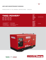
IMPORTANT
A - Tubes, internal diameter 45 mm
B - Tubes, internal diameter 15 mm
C - Clamps
CAUTION
The measurements shown in fig. 4 should
correspond exactly.
IMPORTANT.
A - Tuyauterie d'un diamètre interne de 45 mm.
B - Tuyauterie en caoutchouc Nèoprène d'un diamètre
interne de 15 mm.
C - Bagues de serrage.
ATTENTION
Il est très important de respecter les dimensions
indiquèes sur les figures 4
IMPORTANTE
A - Tubazione diam. 45 mm. interno.
B - Tubazione in neoprene diam. 15 mm interno.
C - Fascette di serraggio.
ATTENZIONE
E' molto importante rispettare le misure
riportate in fig. 4
BELANGRIJK
A - Slangen, inwendige diameter 45 mm.
B - Slangen, inwendige diameter 15 mm.
C - Slangenklemmen
LET OP
Maten zoals aangegeven in fig. 4 dienen
aangehouden te worden.
1 Presa a mare
2 Rubinetto genera acqua
3 Rubinetto svuotamento impianto
4 Filtro acqua
5 Gruppo elettrogeno
6 Marmitta
7 Silenziatore
8 Bocchettone scarico a mare
9 Linea di galleggiamento
Sea intake Prise en mer
General tap-water Robinet gènèral de l’eau
Tap to drain system Robinet de vidage de l’installation
Water filter Filtrè à eau
Electric generator Groupe èletrogène
Mmuffler Pot
Silencer Silencieux
Sea drainage nozzle Goult dècharge en mer
Water line Ligne de flottaison
Huiddoorvoer
Huidafsluiter
Aftapkraan
Wierpot
Generator
Waterslot
Demper
Huiddoorvoer
Waterlijn
Fig. 4

GENERATORS
IS 2500 - 3500 - 4500 - 5500
- 4 -
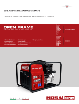
Fig. 5
1 Presa a mare
2 Rubinetto genera impianto
3 Rubinetto svuotamento impianto
4 Filtro acqua
5 Vanvola antisifone
6 Marmitta
7 Silenziatore
8 Bocchettone scarico a mare
9 Linea di galleggiamento
10 Drenaggio
11 Miscelatore di scarico
12 Pompa acqua
13 Gruppo elettrogeno
Sea intake Prise en mer
General tap-systemr Robinet gènèral de l’eau
Tap to drain system Robinet de vidage de l’installation
Water filter Filtrè à eau
Anti-siphon valve Soupape antisiphon
Muffler Pot
Silencer Silencieux
Sea drainage nozzle Goult dècharge en mer
Water line Ligne de flottaison
Drainage Drainage
Drain mixer Mèlangeur de purge
Water pump Pompe à eau
Electric generator Goupe èletrogène
Huidafsluiter
Aftapkraan
Waterfilter
Beluchter
Waterslot
Demper
Huiddoorvoer
Waterlijn
Lekleiding
Waterinjectiebocht
Waterpomp
Generator
IMPORTANT
A - Tubes, internal diameter 45 mm
B - Tubes, internal diameter 15 mm
C - Clamps
CAUTION
The measurements shown in fig. 5 should
correspond exactly.
IMPORTANTE
A - Tubazione diam. 45 mm. interno.
B - Tubazione in neoprene diam. 15 mm interno.
C - Fascette di serraggio.
ATTENZIONE
E' molto importante rispettare le misure
riportate in fig. 5
IMPORTANT.
A - Tuyauterie d'un diamètre interne de 45 mm.
B - Tuyauterie en caoutchouc Nèoprène d'un diamètre
interne de 15 mm.
C - Bagues de serrage.
ATTENTION
Il est très important de respecter les dimensions
indiquèes sur les figures 5.
BELANGRIJK
A - Slangen, inwendige diameter 45 mm.
B - Slangen, inwendige diameter 15 mm.
C - Slangenklemmen
LET OP
Maten zoals aangegeven in fig. 5 dienen
aangehouden te worden.

- 5 -
IS 2500 - 3500 - 4500 - 5500
GENERATORS
1
Fig. 6
Fig. 7
Fig. 8
Fig. 9
Pompa acqua
Water pump
Pompe à l'eau
Waterpomp
1
2
1 Ritorno gasolio •Diesel return • Retourn du gasoil
2 Gasolio • Diesel • Gasoil
Fig. 10
Miscelatore di scarico
Drain mixer
Mèlangeur de purge
Waterinjectiebocht
VALVOLA ANTISIFONE
ANTI-SIPHON VALVE
SOUPAPE ANTISIPHON
BELUCHTER
Valvola antisifone
Anti-siphon valve
Soupape antisiphon
Beluchter

GENERATORS
IS 2500 - 3500 - 4500 - 5500
- 6 -
3
1
2
Fig. 11
IS 2500 - 35000
1
1
3
4
5
2
Fig. 14
Fig. 15
Fig. 12
9X 0,35 mm
1 MARRONE BROWN MARRON BRUIN
2 BIANCO WHITE BLANC WIT
3 BLUE BLUE BLUE BLAUW
4 GRIGIO GREY GRIS GRIJS
5 VERDE GREEN VERT GROEN
6 ROSA PINK ROSE ROZE
7 GIALLO YELLOW JAUNE GEEL
8 NERO BLACK NOIR ZWART
9 ROSSO RED ROUGE ROOD
CALZA EARTH CONDUCT. AFSCHERMINGS-
METALLICA BRAID MATALLIQUE KABE
L
ALLACCIAMENTO CRUSCOTTO / C. PANEL CONNECTION
BRANCHEMENT / AANSLUITINGEN BEDIENINGSPANEEL
NUMERAZIONE
SCHEDA COMANDI
PRINTED CIRCUIT
NUMBERING
NUMERATION
CARTE COMMANDES
PRINTPLAAT
AANSULUITINGEN
COULERCOLOUR
COLORE
Fig. 13
KLEUR
IS 4500/IS 5500

- 7 -
IS 2500 - 3500 - 4500 - 5500
GENERATORS
Fig. 17
Fig. 16
Fig. 18
Fig. 19
Fig. 20
CARICO
LOAD
CHARGE
BELASTING
RETE
MAINS
RESEAU
WALAANSLUTING
CARICO
LOAD
CHARGE
BELASTING
CARICO
LOAD
CHARGE
BELASTING

GENERATORS
IS 2500 - 3500 - 4500 - 5500
- 8 -
1.1 Caratteristiche del vano .................................... 9
1.2 Ancoraggio del gruppo ...................................... 9
1.3 Ventilazione..................................................... 9
2.1. Sistemi di adduzione dell'acqua di mare............ 9
2.2 Tipica installazione con gruppo elettrogeno
sopra la linea di galleggiamento ........................ 9
2.3. Tipica installazione con gruppo elettrogeno
sotto la linea di galleggiamento......................... 9
2.4. Componenti ....................................................10
2.5. Sistema di scarico ..........................................10
3.0 Circuito combustibile .......................................10
4.1. Allacciamento batteria.....................................11
4.2. Allacciamento cruscotto comandi ....................11
4.3. Allacciamento c.a. ..........................................11
4.4. Commutazione generatore - rete ......................12
INDICE
I
IL MANCATO RISPETTO DELLE SPECIFICHE
CONTENUTE NEL SEGUENTE MANUALE DI
INSTALLAZIONE, COMPORTA IL DECADIMENTO
DELLA GARANZIA SUL PRODOTTO
INSTALLAZIONE1
2 CIRCUITO ACQUA DI RAFFREDAMENTO
3 CIRCUITO COMBUSTIBILE
COLLEGAMENTO ELETTRICI4

- 13 -
IS 2500 - 3500 - 4500 - 5500
GENERATORS
INDEX
GB
THE GUARANTEE OF THE PRODUCT BECOMES
VOID IF THE SPECIFICATIONS CONTAINED IN
THE FOLLOWING INSTALLATION MANUAL ARE
NOT RESPECTED
E
1.1 Characteristics of the installation space ......... 14
1.2 Fastening the unit to the ground..................... 14
1.3 Ventilation ..................................................... 14
2.1. Sea water feed system .................................. 14
2.2 Typical installation with electric generator
above the water-line ...................................... 14
2.3. Typical installation with electric generator
below the water-line....................................... 14
2.4. Components.................................................. 15
2.5. Drainage system ........................................... 15
3.0 Fuel circuit..................................................... 15
4.1. Battery connection......................................... 16
4.2. Control panel connection ............................... 16
4.3. A.C. Connection ............................................ 16
4.4. Generator - Mains Switching.......................... 17
INSTALLATION1
2 COOLING WATER CIRCUIT
3 FUEL CIRCUIT
ELECTRICAL CONNECTION4

GENERATORS
IS 2500 - 3500 - 4500 - 5500
- 14 -
GB
1.0. INSTALLATION
1.1. Characteristics of the installation space
The generator must be installed in a sufficiently aired
space, supplying a little amount of air necessary for the
combustion of the motor.
The space must be separate and acoustically insulated
from living areas.
The generator should be positioned so that normal
maintenance operations can easily be carried out.
Propulsion motors are recommended for installation in
the area as long as they comply with the above-mentioned
conditions.
1.2. Fastening the unit to the ground
To fasten the unit securely, a base should be installed to
absorb vibrations and support the weight.
Drill holes in the base according to the instructions in
fig. 1.
1.3. Ventilation
The generator is equipped with an internal forced cooling
system through a water/air exchanger.
The air needed for combustion is taken in through the
opening on the base (fig. 2) so care must be taken to
ensure that this opening is always free.
2.0. COOLING WATER CIRCUIT
In electric generators described in this manual, the motor
is cooled by an open-circuit system in which sea water
circulates.
The capacity of the sea water circuit is 900 l/h (IS 2500)
and 1200 l/h (IS 3500/IS 4500/IS 5500).
On installation a sea water feed circuit should be fitted for
cooling and a waste system to expel the mixture of flue
gas and water.
2.1. Sea water feed system
Boats usually use one of two systems to collect water
(fig. 3):
1 - Direct infeed system
2 - System with baffle
MASE recommend the direct infeed system ref. 1 fig. 3
since this system prevents water under pressure entering
the suction ducts and instead forms a pressure which
can easily be overcome by the water pump of the electric
generator.
IMPORTANT
Do not apply any type of protective hood to the
direct infeed system.
THE DIRECT INFEED SYSTEM SUPPLIED BY MASE
HAS BEEN MODIFIED TO PREVENT SOLID BODIES
ENTERING THE SYSTEM AND BLOCKING IT.
IF OTHER MATERIALS AVAILABLE ON THE MARKET
ARE USED, MORE CARE AND MORE FREQUENT
CLEANING IS NECESSARY.
The baffle system might cause the following problems:
a - If it is installed with the slots facing the prow.
In this case, during navigation and with the electric
generator off, pressure is accumulated in the water
infeed duct which might cause the system to fill up,
even as far as the exhaust port, allowing water to
enter the cylinders.
b - If it is installed with the slots facing the stern.
In this case a depression might accumulate in the
water infeed duct during navigation, preventing the
water pump from starting up the cooling plant, or
limiting the capacity and subsequently causing the
electric generator to overheat.
2.2. Typical installation with electric generator
above the water-line (fig. 4)
2.3. Typical installation with electric generator
below the water line (fig. 5)

- 15 -
IS 2500 - 3500 - 4500 - 5500
GENERATORS
GB
2.4. Components
1 - Direct sea intake 1/2"
IMPORTANT
If the unit is installed more than 1 metre above the
water-line, a check valve should be fitted after the
sea intake (fig. 6, ref. 1) to prevent the water
circuit emptying when the motor is off. If this
empties, the rotor of the water pump might be
damaged during start up; for the same reason,
when the unit is first started up, the suction tube
from the valve to the pump should be filled
manually.
2 - Ball tap (general) 1/2"
3 - Ball tap (drainage) 1/2"
This is used to drain the cooling system of the electric
generator for general maintenance or when a long
period of inactivity is expected.
4 - Water filter (can be inspected)
This must provide efficient protection for the cooling
circuit from the entrance of mud, sand and seaweed.
IMPORTANT
The filter mesh should be very fine. Mesh 2 - 470
micron is recommended, other sizes do not give
good filter performance.
5 - Anti-siphon valve: this valve returns the cooling
circuit to atmospheric pressure when the motor is
switched off, to prevent the siphon phenomenon.
It must be installed when the generator is fitted
with the drainage mixer on or beneath the water
line, and should be positioned at least 50 cm above
water level.(see fig. 8/9)
IMPORTANT
The drainage duct of the anti-siphon valve must
run beneath the valve itself in order to prevent
water accumulating in the duct, which should
always remain empty to allow air to pass through
when the unit is switched off. (see fig. 7)
N.B.: The drainage duct should be taken into the bilge because
during normal operation small quantities of water might be leaked
from the duct.
The box already includes 2 holes to connect the anti-siphon valve
(fig. 9).
2.5. Drainage system
The flue gas/water drainage system of the generator
must be separate from that of the main motors
IMPORTANT
The length of the tube from the highest point of
the drain duct to the muffler should not exceed 2
metres. This is to prevent the water left in the
drainage duct returning to the motor after filling
the tank muffler, when the unit is turned off.
1 - Tank muffler (capacity 3.5 litres)
This dampens the noise of the drainage and stops
the water flowing back towards the motor. The muffler
should be installed no less than 1 metre away from
the generator and positioned at a height less than or
equal to that of the base plate of the generator.
2 - Silencer
This further reduces noise. It should be installed no
more than 1 metre from the sea drainage nozzle.
3 - Sea drainage nozzle; It should be installed so that it
is always above the water line.
3.0. FUEL CIRCUIT
The unit is fed by diesel fuel through the tubes marked
“DIESEL” and “DIESEL RETURN” (fig. 10, ref. 1-2). This
latter is used for the return of the excess fuel. It is
necessary to install a filter in connections to the fuel
tank, it is also advisable to fit a tap onto the power supply
line downstream of the tank and a single-acting valve
(check valve only for a difference in height of 50 cm or
more) to prevent the fuel system emptying for any
reason. Use a valve with a 50 millibar opening.
The fuel pipes should be in hydrocarbon-resistant rubber,
of inner diameter 6 mm.
IMPORTANT
The unit is fitted with automatic diesel oil
drainage. If manual drainge is necessary, press
the "ON" button and 30 second before set going
the unit.
IMPORTANT
The fuel filter must be a "cartridge-type" with a
filtering grade of 5 to 10 micron

GENERATORS
IS 2500 - 3500 - 4500 - 5500
- 16 -
GB
4.0. ELECTRICAL CONNECTIONS
4.1. Battery connection
To start off the unit an independent battery of 12V is
needed, capacity 18 - 30 Ah min.
It should be connected to the clamp of the generator as
shown in fig. 11 with cables of section 25 mm
2
up to
distances of 5 metres and with cables of section 35 mm
2
for longer distances, and following the sequence of
operations described below:
- First connect the positive pole (+) of the battery to the
terminal marked with the symbol (+) on the generator,
(the starter).
- Then connect the negative pole (-) of the battery to the
terminal marked with the symbol (-) on the generator.
- Wipe the connections with special mineral grease to
protect against oxidation and corrosion.
The generator includes an electronic device to
automatically recharge the start-up battery, giving 10
A, at a voltage of 12 V, when fully charged.
IMPORTANT
Install the battery in a well-ventilated area, away
from the generator and from any device which
might produce heat or sparks.
Periodically check the state of the connections of
the terminals and the water level of the battery. If
the cables need to be disconnected, follow the
instructions for connection in reverse order.
Do not invert the poles of the connecting cables
since serious damage might be caused to the
generator and the battery.
Do not connect other loads to the battery.
In order to reduce galvanic currents to a minimum, the (-
) of the battery of the electric generator should not be
connected to the (-) of the other batteries on board.
4.2. Control panel connection
This connection can be made through the terminal
boards (fig. 12, ref. 1) using the cables provided already
connected to the control panel. The terminals to be used
are those marked no. 1 to no. 9 for the control cables. The
earths braid should be connected to the faston terminal
(fig. 12, ref. 2) insulating them carefully and using a pre-
insulated female faston. In making the connections it is
important to follow the diagram and the colours codes as
indicate (fig. 13). Fasten the cable with the provided
plastic support on the bail (fig. 12, ref. 3).
The control panel contains 5 LEDs for operation and
alarm (fig. 14, ref. 1), an hour counter (fig. 14, ref. 2) and
the start and stop buttons (fig. 14, ref. 3/4/5).
For fixing the control panel is necessary to perforate as
shown in fig.14.
IMPORTANT
The control panel is indispensable for operating
the unit and must be installed; do not use devices
othet than the control panel supplied with the unit
since they might not be compatible with the
generator.
Make the connections with the battery
disconnected.
CAUTION
The control panel is provided with a connecting
cable 10 metres long. This cable should not be
modified since it might cause the panel circuit to
function incorrectly.
4.3. A.C. Connection
This connection can be done through the power terminal
board (fig. 15, ref. 1) placed inside the derivation box.
This range includes the possibility of use both at 115V
50Hz - 120V 60Hz and 230V 50Hz - 240V 60Hz.
For this reason it is possible to make two types of
connection (and use), according to the following
configurations.
1 - Parallel configuration: in this configuration there is a
single output at 115 (120) V between points P
1
and
F
2
, connecting the outputs of the alternator (P
1
, F
1
,
P
2
, F
2
) as shown in the diagram in fig. 16.
2 - Serial connection; in this configuration it is possible
to use a voltage of 230 (240) V between points P
1
and
F
2
, as shown in the diagram in fig. 17.
In serial connection, power can be picked up both at 110
(120) V between points F
1
- F
2
and P
1
- P
2
and at 220 (240)
V between points P
1
and F
2
at the same time, as shown
in the diagram in fig. 18.
It is also possible to feed two separate lines as shown in
fig. 19 on the outputs P
1
- F
1
and P
2
- F
2
.

- 17 -
IS 2500 - 3500 - 4500 - 5500
GENERATORS
GB
N.B. In this case the power which can be taken from each of the
two outputs is half the rated nominal power.
- Ensure that the sum of the loads to be supplied does
not exceed the nominal power of the electric generator.
- Magnetothermic protective devices or similar should
be placed between the generator and electrical
equipment, according to the tables shown below.
- To make both parallel and serial connections, use the
special bridges provided in the accessories to the
electric generator on the terminal board fig. 15 ref. 1.
Single voltage distribution
N.B: In these cases just one magnetothermic device should be
installed, see fig. 16/17.
Double voltage distribution
N.B: In these cases two magnetothermic devices should be
installed, see fig. 18/19, dimensioned on the current values (A)
shown in Table. 2.
4.4. Generator - Mains switching
A switch should be placed on the line to switch the user
appliances from the generator to an external power line.
The switch should be dimensioned according to the size
of the loads: a general diagram is shown in fig. 20.
Hz 60 60 60
V 120/240 120/240 120/240
W 1900 2900 4800
A 7.9 12.1 20
IS 4500/IS 5500IS 2500
IS 3500
Hz 50 50 50
V 115/230 115/230 115/230
W 1700 2700 4000
A 7.4 11.7 17.4
Hz 50 60 50 60
V 115 120 230 240
W. 1700 1900 1700 1900
A 14.8 15.8 7.4 7.9
TAB 1
Hz 50 60 50 60
V 115 120 230 240
W. 4000 4800 4000 4800
A 34.8 40 17.4 20
Hz 50 60 50 60
V 115 120 230 240
W. 2700 2900 2700 2900
A 23.5 24.2 11.7 12.1
IS 3500
IS 2500
IS 4500/IS 5500

Mase Generators S.p.a. • Via Tortona, 345 • 47023 Cesena (FC) ITALY • Tel. (+39) 0547.35.43.11
/