Page is loading ...

CLIMATE
AIR CONDITIONERS
MCS T6, MCS T12, MCS T16
Marine Air Conditioner
Installation Manual . . . . . . . . . . . . . . . . . .10
Bootsklimaanlage
Montageanleitung . . . . . . . . . . . . . . . . . 33
Climatiseur pour bateau
Instructions de montage. . . . . . . . . . . . . 56
Equipo de aire acondicionado
para embarcaciones
Instrucciones de montaje . . . . . . . . . . . . 80
Sistema de ar condicionado de
barco
Instruções de montagem . . . . . . . . . . . 103
Impianto di condizionamento
Indicazioni di montaggio . . . . . . . . . . . 126
Bootairco
Montagehandleiding . . . . . . . . . . . . . . 149
Marineklimaanlæg
Monteringsvejledning . . . . . . . . . . . . . 172
Båtklimatanläggning
Monteringsanvisning . . . . . . . . . . . . . . . 195
Klimaanlegg for båter
Monteringsanvisning . . . . . . . . . . . . . . . 218
Veneilmastointilaite
Asennusohje . . . . . . . . . . . . . . . . . . . . . 240
Судовой кондиционер
Инструкция по монтажу . . . . . . . . . . . 263
System klimatyzacji dla łodzi
ijachtów
Instrukcja montażu . . . . . . . . . . . . . . . . 286
Lodné klimatizačné zariadenie
Návod na montáž . . . . . . . . . . . . . . . . . . 310
Lodní klimatizace
Návod k montáži. . . . . . . . . . . . . . . . . . 334
Hajó-klímaberendezés
Szerelési útmutató . . . . . . . . . . . . . . . . 357
EN
DE
FR
ES
PT
IT
NL
DA
SV
NO
FI
RU
PL
SK
CS
HU
MCS-T6-T12-T16--I-16s.book Seite 1 Dienstag, 14. November 2017 11:09 11

3
MCS T6, MCS T12, MCS T16
5 6
14
22 3
1
2
2.
3.
6“MR
7“MR
1.
4.
4x
4x
MCS-T6-T12-T16--I-16s.book Seite 3 Dienstag, 14. November 2017 11:09 11

MCS T6, MCS T12, MCS T16
4
B
A
3
4
1
2 3
4
5
6
1
2
5
MCS-T6-T12-T16--I-16s.book Seite 4 Dienstag, 14. November 2017 11:09 11

5
MCS T6, MCS T12, MCS T16
1
2
3
4
5
5
6
6
7
8
9
7
4
3
2
1
5
6
7
4
3
2
1
A
B
C
D
5
6
7
4
3
1
10
10
10
6
MCS-T6-T12-T16--I-16s.book Seite 5 Dienstag, 14. November 2017 11:09 11

MCS T6, MCS T12, MCS T16
6
7
8
1
16
2
3
4
5
6
7
8910
11
12
13
14
15
MCS-T6-T12-T16--I-16s.book Seite 6 Dienstag, 14. November 2017 11:09 11

7
MCS T6, MCS T12, MCS T16
A
2
3
4
6
7
8
9
10
11
1
12
14
15
16
17
18
20
13
19
5
9
9
MCS-T6-T12-T16--I-16s.book Seite 7 Dienstag, 14. November 2017 11:09 11

EN
Explanation of symbols MCS T6, MCS T12, MCS T16
10
Please read this instruction manual carefully before installation and
first use, and store it in a safe place. If you pass on the product to
another person, hand over this instruction manual along with it.
Contents
1 Explanation of symbols . . . . . . . . . . . . . . . . . . . . . . . . . . . . . . . . . 10
2 Safety Instructions . . . . . . . . . . . . . . . . . . . . . . . . . . . . . . . . . . . . . 11
3 Target Group . . . . . . . . . . . . . . . . . . . . . . . . . . . . . . . . . . . . . . . . . . 12
4 Scope of Delivery . . . . . . . . . . . . . . . . . . . . . . . . . . . . . . . . . . . . . . 12
5 Intended Use . . . . . . . . . . . . . . . . . . . . . . . . . . . . . . . . . . . . . . . . . . 16
6 Technical Description . . . . . . . . . . . . . . . . . . . . . . . . . . . . . . . . . . . 16
7 Unpacking and inspection of the scope of delivery . . . . . . . . . . 17
8 Installation . . . . . . . . . . . . . . . . . . . . . . . . . . . . . . . . . . . . . . . . . . . . 17
9 Connecting the Marine Climate System MCS T . . . . . . . . . . . . . . 29
10 Operation. . . . . . . . . . . . . . . . . . . . . . . . . . . . . . . . . . . . . . . . . . . . . 30
11 Programming. . . . . . . . . . . . . . . . . . . . . . . . . . . . . . . . . . . . . . . . . . 30
12 Troubleshooting Guidelines . . . . . . . . . . . . . . . . . . . . . . . . . . . . . 30
13 Warranty . . . . . . . . . . . . . . . . . . . . . . . . . . . . . . . . . . . . . . . . . . . . . 31
14 Disposal . . . . . . . . . . . . . . . . . . . . . . . . . . . . . . . . . . . . . . . . . . . . . . 31
15 Technical Data . . . . . . . . . . . . . . . . . . . . . . . . . . . . . . . . . . . . . . . . . 32
1 Explanation of symbols
!
!
A
WARNING!
Safety instruction: Failure to observe this instruction can cause fatal or
serious injury.
CAUTION!
Safety instruction: Failure to observe this instruction can lead to injury.
NOTICE!
Failure to observe this instruction can cause material damage and impair the
function of the product.
MCS-T6-T12-T16--I-16s.book Seite 10 Dienstag, 14. November 2017 11:09 11

11
EN
MCS T6, MCS T12, MCS T16 Safety Instructions
I
2 Safety Instructions
The manufacturer accepts no liability for damage in the following cases:
•
Faulty assembly or connection
•
Damage to the product resulting from mechanical influences and excess
voltage
•
Alterations to the product without express permission from the manufacturer
•
Use for purposes other than those described in the operating manual
2.1 General Safety
!
WARNING!
•
Danger of electrocution!
The units are AC voltage components, running on 230 V~.
•
Electrical shock hazard!
Disconnect voltage at main panel or power source before opening any
cover.
Failure to comply may result in injury or death.
•
To minimize the hazard of electrical shock and personal injury, this compo-
nent must be effectively grounded.
•
This system does not meet requirements for ignition protection. Do not install
in spaces containing gasoline engines, tanks, LPG/CPG cylinders, regula-
tors, valves or fuel line fittings.
Failure to comply may result in injury or death.
•
Do not terminate condensate drain line
– within 1 m of any outlet of engine or generator exhaust systems,
– in a compartment housing of an engine or generator,
– in a bilge, unless the drain is connected properly to a sealed condensate
or shower sump pump.
Failure to comply may allow bilge or engine room vapors to mix with the air
conditioners return-air and contaminate living areas which may result in
injury or death.
•
In order to prevent the ingress of carbon monoxide (CO) or other harmful
vapors, a trap should be installed in the condensate drain line(s).
•
Installation and servicing of this system can be hazardous due to system pres-
sure and electrical components.
•
Never install your air conditioner in the bilge or engine room areas.
•
Place a fire extinguisher close to the work area.
NOTE
Supplementary information for operating the product.
MCS-T6-T12-T16--I-16s.book Seite 11 Dienstag, 14. November 2017 11:09 11

EN
Target Group MCS T6, MCS T12, MCS T16
12
!
CAUTION!
•
Wear safety glasses and work gloves.
A
NOTICE!
•
Attach the air conditioner unit to a solid level platform with the four mounting
brackets provided.
2.2 Safety Handling Electrical Cables
!
CAUTION!
•
Attach and lay the cables in such a manner that they cannot be tripped over
or damaged.
A
NOTICE!
•
Use cable ducts to run cables through walls and bulkheads with sharp edges.
•
Do not lay loose or bent cables next to electrically conductive materials
(metal).
•
Do not pull on the cables.
3Target Group
The instructions in this manual are intended for qualified personnel at workshops
who are familiar with the guidelines and safety precautions to be applied.
4 Scope of Delivery
I
NOTE
Each unit includes a condensate hose barb assembly and 4 mounting brackets.
MCS-T6-T12-T16--I-16s.book Seite 12 Dienstag, 14. November 2017 11:09 11

13
EN
MCS T6, MCS T12, MCS T16 Scope of Delivery
4.1 Marine Climate System MCS T6
MCS T6 – Complete Kit (part no. 9600000549)
Duct Kit
Seawater Kit
Accessories
Quantity Description
1 DTU6 unit only
1Control panel
1 Electrical box
1 Display cable
Quantity Description
3.8 m Ducting, insulated, 100 mm/4" ID
1 Supply-air grille 4"x 4", 102 x 102 mm
1 Return-air grille 10"x 8", 254 x 203 mm, anodized
Quantity Description
1 Thru-hull, 5/8", plastic
7.6 m Seawater Hose, 5/8"
3 PVC adapter, 1/2" MPT x 1/2" HB
2 PVC adapter, 1/2" FPT x 1/2" HB
1 Strainer, 1/2", with bracket 1/2" FPT
1 Seawater pump PML250 (220 Vw, 50/60 Hz)
17 Hose clamps, thin
1 Ball valve, 1/2", bronze
1 Speed scoop, 1/2", bronze
Quantity Description
1Hose barb assembly
4 Mounting brackets
1Return air filter
MCS-T6-T12-T16--I-16s.book Seite 13 Dienstag, 14. November 2017 11:09 11

EN
Scope of Delivery MCS T6, MCS T12, MCS T16
14
4.2 Marine Climate System MCS T12
MCS T12 – Complete Kit (part no. 9600000550)
Duct Kit
Seawater Kit
Spare Parts
Quantity Description
1 DTU12 unit only
1Control panel
1 Electrical box
1 Display cable
Quantity Description
3.8 m Ducting, insulated, 150 mm/6" ID
1 Supply-air grille 10"x 6", 254 x 153 mm
1 Return-air grille 14"x 10", 356 x 254 mm, anodized
Quantity Description
1 Thru-hull, 5/8", plastic
7.6 m Seawater Hose, 5/8"
3 PVC adapter, 1/2" MPT x 1/2" HB
2 PVC adapter, 1/2" FPT x 1/2" HB
1 Strainer, 1/2", with bracket 1/2" FPT
1 Seawater pump PML250 (220 Vw, 50/60 Hz)
17 Hose clamps, thin
1 Ball valve, 1/2", bronze
1 Speed scoop, 1/2", bronze
Quantity Description
1Hose barb assembly
4Mounting brackets
1 Return air filter
MCS-T6-T12-T16--I-16s.book Seite 14 Dienstag, 14. November 2017 11:09 11

15
EN
MCS T6, MCS T12, MCS T16 Scope of Delivery
4.3 Marine Climate System MCS T16
MCS T16 – Complete Kit (part no. 9600000551)
Duct Kit
Seawater Kit
Spare Parts
Quantity Description
1 DTU16 unit only
1Control panel
1 Electrical box
1 Display cable
Quantity Description
3.8 m Ducting, insulated, 150 mm/6" ID
1 Supply-air grille 10"x 8", 254 x 203 mm
1 Return-air grille 14"x 10", 356 x 254 mm
1 6" Duct Ring
4Push rivets
Quantity Description
1 Thru-hull, 5/8", plastic
7.6 m Seawater Hose, 5/8"
3 PVC adapter, 1/2" MPT x 1/2" HB
2 PVC adapter, 1/2" FPT x 1/2" HB
1 Strainer, 1/2", with bracket 1/2" FPT
1 Seawater pump PML500 (220–240 Vw,
50/60 Hz)
17 Hose clamps, thin
1 Ball valve, 1/2", bronze
1 Speed scoop, 1/2", bronze
Quantity Description
1 Hose barb assembly
4Mounting brackets
1 Return air filter
MCS-T6-T12-T16--I-16s.book Seite 15 Dienstag, 14. November 2017 11:09 11

EN
Intended Use MCS T6, MCS T12, MCS T16
16
5 Intended Use
The Marine Climate System MCS T is an air conditioning system designed for use
on boats or yachts. It can cool down or warm up the interior of the vessel.
6 Technical Description
The Marine Climate System MCS T marine air conditioner is designated to run on
230 Vw.
The Marine Climate System MCS T kit consists of the following components:
•
DTU self contained A/C unit
•
Control panel and display cable
•
Ducting
•
Supply-air grille
•
Return-air grille
•
Seawater pump
•
Strainer
•
Speed scoop thru-hull
•
Overboard discharge fitting
•
Seawater hose
•
Fittings for pump and strainer
The system is a seawater cooled air conditioning system.
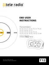
6.1 Components of the Marine Climate System MCS T
MCS T16 only:
The DTU unit T16 is supplied with a 7" duct ring.
➤ Replace the 7" duct ring with the 6" duct ring using the 4 rivets supplied
(fig. 2, page 3).
Item in
fig. 1, page 3
Description
1Duct ring
2Mounting bracket
3 Condensate drain (two of three locations shown)
4 Composite base pan
5 Rotary compressor
6 Rotable blower assembly
MCS-T6-T12-T16--I-16s.book Seite 16 Dienstag, 14. November 2017 11:09 11

17
EN
MCS T6, MCS T12, MCS T16 Unpacking and inspection of the scope of delivery
7 Unpacking and inspection of the scope of
delivery
➤ Check all items against the packing list to ensure all cartons have been
received.
➤ Move units in the normal “up” orientation as indicated by the arrows on each
carton.
➤ Examine cartons for shipping damage, removing the units from the cartons if
necessary.
➤ If the unit is damaged, the carrier should make the proper notation on the
delivery receipt acknowledging the damage.
8 Installation
!
•
Plan all connections which must be made including
– ducting,
– condensate drain,
– seawater in and out,
– electrical power connections,
– location of control,
– seawater pump placement,
to assure easy access for routing and servicing.
I
CAUTION! Danger of injury
The system may only be installed by qualified personnel from a specialist com-
pany. The following information is intended for technicians who are familiar
with the guidelines and safety precautions to be applied.
NOTE
Review the following notes prior to and after installation.
MCS-T6-T12-T16--I-16s.book Seite 17 Dienstag, 14. November 2017 11:09 11

EN
Installation MCS T6, MCS T12, MCS T16
18
8.1 Spacing Allowances and Unit Dimensions
See fig. 3, page 4:
I
Space allowances (fig. 3, page 4)
The following space allowances should be considered when mounting the unit:
•
Allow a minimum of 152 mm clearance around the unit in the area of the sea-
water and condensate drain piping.
•
Allow a minimum of 76 mm of air space in front of the evaporator coil for the
return-air intake if it is adjacent to a bulkhead.
•
For flexible ducting connection and for clearance needed behind the supply-
air grille add the following values to get the total clearance distance:
– 51 mm for the duct ring
– 25 mm for the duct bend radius and
– diameter of the ducting.
•
Allocate enough space for installation and serviceability.
Unit dimensions
NOTE
The blower is rotatable by 270 degrees, to ease installation and improve air
flow.
Unit Capacity 6 T 12 T 16 T
Minimum duct diameter (mm)
102 152 152
Minimum duct area (cm
2
)
81 183 183
Minimum distance return grill (cm
2
)
413 839 1032
Minimum distance supply grill (cm
2
)
206 452 516
MCS-T6-T12-T16--I-16s.book Seite 18 Dienstag, 14. November 2017 11:09 11

19
EN
MCS T6, MCS T12, MCS T16 Installation
8.2 Condensate Drains
!
Mind the following notes on the installation of the condensate drains:
•
Do not route condensate drains to the bilge.
•
Run the condensate drain line downward from the unit to a suitable drain
location.
•
The condensate drain line should have a trap.
For installation of the condensate drain (fig. 4, page 4):
➤ Remove the aft facing watertight plug (3) from the base pan (2) of the air
conditioning unit using the hose barb (1).
➤ Screw the hose barb into the drain hole and tighten it (4).
➤ Secure the drain hose with a stainless steel hose clamp (5).
➤ Install the condensate drain hose downhill from the unit and to a safe and
proper collection point (6).
The hose should have a trap.
I
➤ Test the installation by pouring one liter of water into the base pan and check-
ing for good flow.
WARNING!
Do not terminate condensate drain line
– within 1 m of any outlet of engine or generator exhaust systems,
– in a compartment housing of an engine or generator,
– in a bilge, unless the drain is connected properly to a sealed
condensate or shower sump pump.
Failure to comply may allow bilge or engine room vapors to mix with the air
conditioners return-air and contaminate living areas which may result in injury
or death.
NOTE
•
Two drain fittings may be used and the hoses teed together provided there
is a minimum 50 mm drop from the bottom of the base pan to the tee
connection.
•
Consideration should be given to installing a trap in the condensate drain
line(s) so that normal discharge of condensate can fill the trap and prevent
the ingress of carbon monoxide (CO) or other potentially harmful vapors.
MCS-T6-T12-T16--I-16s.book Seite 19 Dienstag, 14. November 2017 11:09 11

EN
Installation MCS T6, MCS T12, MCS T16
20
8.3 Blower Assembly
Rotate the blower to allow the most direct flow of air to the supply-air grille
(fig. 5, page 4).
➤ Loosen the adjustment screw (1).
➤ Rotate the blower (2).
➤ Tighten the adjustment screw (1).
8.4 Electrical Box
Mind the following notes on the installation of the electrical box (fig. 8 3,
page 6):
•
Mount the electrical box in a dry location.
•
Mount the electrical box to a flat, solid surface within 1 m of the unit.
•
Mount the electrical box within 4.5 m of the location where the digital con-
trol will be installed.
➤ Use the 4 mounting slots in the back of the electric box to attach it to a suita-
ble mounting surface.
➤ Use screws appropriate for mounting surface (not included).
8.5 Supply-Air Grille
Mind the following notes on the installation of the supply-air grille to ensure
direct uninterrupted airflow from the blower:
A
•
Install the supply-air grille as high as possible.
•
A minimum clearance of 76 mm plus the duct diameter size is required
behind the supply-air grille for attaching the ducting.
➤ Create the cut outs for the supply-air grille according to the following table:
➤ Mount the supply-air grille.
NOTICE!
In no instance should the supply-air grille discharge be directed towards the
return-air grille, as this will cause the system to short cycle.
MCS T6 MCS T12 MCS T16
4.9" x 4.9"
125 x 125 mm
9.9" x 5.9"
252 x 150 mm
9.9" x 7.9"
252 x 201 mm
MCS-T6-T12-T16--I-16s.book Seite 20 Dienstag, 14. November 2017 11:09 11

21
EN
MCS T6, MCS T12, MCS T16 Installation
8.6 Return-air Grille
Mind the following notes on the installation of the return-air grille to ensure direct
uninterrupted airflow to the evaporator:
•
Install the return-air grille as low and as close to the unit as possible.
•
Install the return-air grille away from exhaust and bilge vapors.
•
The return-air grille should have a minimum of 107 mm of clearance in front of
it in the cabin area (fig. 3, page 4).
➤ Create the cut out for the return-air grilles according to the following table:
➤ If your kit is supplied with a filtered return-air grille: Remove the filter attached
to the unit’s evaporator and discard it.
Two filters are not better than one, as the reduced air flow will decrease per-
formance and possibly freeze the evaporator coil.
➤ Mount the return-air grille.
8.7 Ducting
Mind the following notes on the installation of the ducting:
•
The ducting should be run as straight, smooth and taut as possible.
•
Avoid any unnecessary bends and loops. Rotate the blower instead.
•
Minimize the number of 90° bends (two tight 90° bends can reduce airflow
by 25 %).
•
Ensure the ducting is properly connected with no excess.
Proceed as follows to install the ducting:
➤ Start at either end (the air-discharge grille or the air conditioning unit).
➤ Pull back the fiberglass insulation exposing the inner mylar duct hose.
➤ Slide the inner mylar duct hose around the mount ring until it bottoms out.
➤ Screw 3 or 4 stainless steel sheet metal screws through the duct hose into the
transition ring.
Make sure to catch the wire in the duct hose with the heads of the screws.
Do not use band clamps, as the hose will slide off.
➤ Wrap duct tape around the ducting and ring joint to prevent any air leaks.
➤ Pull the insulation back up over the mylar to the ring and tape this joint.
MCS T6 MCS T12 MCS T16
9.9" x 7.9"
252 x 201 mm
13.9" x 9.9"
353 x 252 mm
13.9" x 9.9"
353 x 252 mm
MCS-T6-T12-T16--I-16s.book Seite 21 Dienstag, 14. November 2017 11:09 11

EN
Installation MCS T6, MCS T12, MCS T16
22
➤ Run the ducting to the other end, keeping it as straight, smooth, and taut as
possible.
➤ Remove excess ducting.
➤ Use the same connection method at the other end.
8.8 Control Panel Installation
Mind the following notes on the installation of the control panel (fig. 8 2,
page 6):
•
Mount the control panel (2) within 4.5 m of the electrical box (3).
•
Mount the control panel on an inside wall, slightly higher than mid-height of
the cabin, in a location with freely circulating air where it can best sense aver-
age temperature.
•
Do not mount the control panel
– in direct sunlight,
– near any heat producing appliances
– in a bulkhead where temperatures radiating from behind the panel may
affect performance
– in the supply-air stream
– above or below a supply or return-air grille
Before mounting the control panel, consider the location:
➤ Create a cut out size for the control panel:
64 mm (width) x 48 mm (height).
➤ Plug one end of the display cable (8-pin RJ-45 connector) into the display
socket J1 (fig. 0 4, page 8) of the electric box and the other end into the
back of the control panel.
➤ Remove jumper JP5 (fig. 0 14, page 8) of the electric box to activate
display.
➤ Prior to placement clean the mounting surface with isopropyl alcohol only
(test alcohol on hidden portion of surface first).
➤ Secure the control panel to a bulkhead with the adhesive strips provided.
MCS-T6-T12-T16--I-16s.book Seite 22 Dienstag, 14. November 2017 11:09 11

23
EN
MCS T6, MCS T12, MCS T16 Installation
8.9 Remote Air Sensor Installation (optional)
Install the optional remote air sensor if the display cannot be mounted in a proper
location for accurately sensing room temperature. Installing the remote sensor
overrides the display‘s built-in sensor. The standard cable length for the remote
air sensor is 5 ft (1.5 m).
➤ Mount the remote air sensor (fig. 8 4, page 6) in the plastic clip mounted
on the return air side of the evaporator.
➤ Plug the cable (6-pin connector) into the ALT AIR socket (J3)of the circuit
board (fig. 0 5, page 8).
MCS-T6-T12-T16--I-16s.book Seite 23 Dienstag, 14. November 2017 11:09 11
/