Page is loading ...

Copyright January 1, 2017
Jim M. Bagley, GraceWood, Inc
(Reproduction Prohibited)
Version 1
21in Sewing Machine

Table of Contents ...................................................................................................................... i
Safety Instructions
General Warnings ....................................................................................................................iii
Grounding Instructions .............................................................................................................iv
Technical Data
Specifications ...........................................................................................................................v
Feature Overview ....................................................................................................................vi
Parts & Tools ..........................................................................................................................vii
Setup & Assembly
Wheel Assembly ...................................................................................................................... 1
Handle Assembly ..................................................................................................................... 2
Handle Adjustment .................................................................................................................. 3
Display and Thread Mast Setup ................................................................................................. 4
Carriage Adjustment ................................................................................................................ 5
Plastic Base Assembly .............................................................................................................. 6
Encoder Assembly.................................................................................................................... 7
Encoder Cables ........................................................................................................................ 9
Threading The Sewing Machine ................................................................................................ 11
Winding The Bobbin ................................................................................................................15
Installing The Bobbin Case ......................................................................................................17
Adjusting Thread Tension ........................................................................................................18
Plugging In The Cables ............................................................................................................19
Final Checklist ........................................................................................................................20
Sewing
Basic Controls ......................................................................................................................... 21
Main Menu .............................................................................................................................22
Sewing Modes ........................................................................................................................23
Tools Menu ............................................................................................................................25
Maintenance
Replacing The Encoder Spring .................................................................................................. 29
Needle Plate ...........................................................................................................................30
Hook Holder ...........................................................................................................................31
Timing The Machine ................................................................................................................32
Hopping Foot .........................................................................................................................34
Thread Tension .......................................................................................................................36
Changing the Needle ...............................................................................................................37
Cleaning & Oiling The Machine .................................................................................................39
Troubleshooting
Troubleshooting Instructions ....................................................................................................40
i
Table of Table of Contents

Appendix
Needle Information ..................................................................................................................ix
Thread Information ...................................................................................................................x
Additional Tips .........................................................................................................................xi
ii
Table of Table of Contents

When using an electrical machine, basic safety precautions should always be followed, including the following:
Read all instructions before using this machine.
DANGER - To reduce the risk of electric shock:
The machine should never be left unattended when plugged in. Always unplug this
machine from the electric outlet immediately after using and before cleaning.
WARNING - To reduce the risk of burns, fire, electric shock, or injury to persons:
1. Do not allow this machine to be used as a toy. Close attention is necessary when this machine is used by or near
children.
2. Use this machine only for its intended use as described in this manual. Use only attachments recommended by the
manufacturer as contained in this manual.
3. Never operate this machine if it has a damaged cord or plug, if it is not working properly, if it has been dropped
or damaged, or dropped into water. Return the machine to the nearest authorized dealer or service center for
examination, repair, electrical or mechanical adjustment.
4. Never operate the machine with any air openings blocked. Keep ventilation openings of the sewing machine free
from the accumulation of lint, dust, and loose cloth.
5. Never drop or insert any object into any opening.
6. Do not use outdoors.
7. Do not operate where aerosol (spray) products are being used or where oxygen is being administered.
8. To disconnect, turn all controls to the off position, then remove the plug from the outlet.
9. Do not unplug by pulling on cord. To unplug, grasp the plug, not the cord.
i. Keep fingers away from all moving parts. Special care is required around the sewing machine needle.
ii. Always use the proper needle plate. The wrong plate can cause the needle to break.
iii. Do not use bent needles.
iv. Do not pull or push fabric while stitching. It may deflect the needle causing it to break.
v. Switch the sewing machine off when making any adjustments in the needle area, such as threading needle,
changing needle, threading bobbin, or changing presser foot, etc.
vi. Always unplug sewing machine from the electrical outlet when removing covers, lubricating, or when making
any other user servicing adjustments mentioned in the instruction manual.
Connect this machine to a properly grounded outlet only. See Grounding Instructions.
SAVE THESE INSTRUCTIONS
DO NOT DISCARD BOX OR PACKAGING
This appliance is not intended for use by persons (including children) with reduced physical, sensory or mental capabilities,
or lack of experience and knowledge, unless they have been given supervision or instruction concerning use of the appliance
by a person responsible for their safety. Children should be supervised to ensure that they do not play with the appliance.
If the supply cord is damaged, it must be replaced by the manufacturer, its service agent or similarly qualified persons in
order to avoid a hazard.
The instructions shall state the maximum power input of any lamp and its rated voltage if it is lower than the rated voltage
of the appliance.
The instructions shall state the substance of the following
• Switch off or unplug the appliance when leaving it unattended
• Unplug the appliance before carrying out maintenance or replacing lamps.
The instructions for electrical sets shall indicate the sewing machines for which they are intended and shall state how they
are to be installed. The appliance is only intended for the purpose described in user manual. Do not use appliance or any
part of the appliance out of the intended use to avoid risk. The use of attachments which are not recommended or sold by
the appliance manufacturer may cause a risk of injury to persons. Household and Indoor use only. To protect against the
risk of electrical shock, do not immerse the unit, cord or plug in water or other liquid.
iii
|Saftey Instructions General Warnings

Grounding Methods
Figure 61.1
(B)
Cover of
Grounded
Outlet Box
Metal
Screw
(A)
Grounding
Pin
Surge
Protector
To Sewing
Machine
(C)
Adapter
Grounding
Means
(D)
Grounding
PIN
Surge
Protector
To Sewing
Machine
GROUNDING INSTRUCTIONS
This product must be grounded. In the event of malfunction or breakdown, grounding provides a path
of least resistance for electric current to reduce the risk of electric shock. This product is equipped
with a cord having an equipment-grounding conductor and a grounding plug. Plug the cord from the
quilting machine into a surge protector. The surge protector must be plugged into an appropriate
outlet that is properly installed and grounded in accordance with all local codes and ordinances.
DANGER - Improper connection of the equipment-grounding
conductor can result in a risk of electric shock.
The conductor with insulation having an outer surface that is green with or without yellow stripes
is the equipment-grounding conductor. If repair or replacement of the cord or plug is necessary,
do not connect the equipment-grounding conductor to a live terminal. Check with a qualified
electrician or serviceman if the grounding instructions are not completely understood, or if in
doubt as to whether the product is properly grounded. Do not modify the plug provided with the
product - if it will not fit the outlet, have a proper outlet installed by a qualified electrician.
This product is for use on a nominal 120 V circuit, and has a grounding plug that looks like the plug
illustrated in sketch A in Figure 61.1. A temporary adaptor, which looks like the adaptor illustrated in
sketches B and C, may be used to connect this plug to a 2-pole receptacle as shown in sketch B if a
properly grounded outlet is not available. The temporary adaptor should be used only until a properly
grounded outlet can be installed by a qualified electrician. The green colored rigid ear, lug, and the
like, extending from the adaptor must be connected to a permanent ground such as a properly
grounded outlet box cover. Whenever the adaptor is used, it must be held in place by the metal screw.
iv
|Saftey Instructions Grounding Instructions

1. Height: 515 mm, 20.25”
2. Width: 395 mm, 15.5”
3. Length: 824 mm, 32.4”
4. Weight: 54 lbs.
5. Quilting Arm Length: 21” W 10.5” H
6. Maximum Stitches Per Minute: 1800
7. Minimum Stitches Per Minute: 90
8. Input Voltage: 110-220 VAC
9. Peak Power Consumption: 300 W
10. Timing Belt System
11. Bobbin Type: Large M Class
12. OLED Screen
13. Custom Ergonomic Handles and Handlebars
for efficiency and extended use
14. Built in Bobbin Winder
15. Dual Thread Tension Guides, for precise
tension.
v
|Technical Data Specifications
Front
Right
Left
Rear

1. Thread Mast Base
2. Bobbin Thread Guide
3. Bobbin Thread Tensioner
4. Bobbin Thread Cutter
5. Bobbin Wind Stand
6. Bobbin Sensor
7. Dual Thread Tension Guide
8. Small Thread Tensioner
9. Large Thread Tensioner
10. Thread Guides
11. Take Up Lever
12. Lamp
13. Needle Bar
14. Needle
15. Hopping Foot
16. Thread Stand
17. Carriage wheels
18. Hand wheel
19. Bobbin Case
vi
|Technical Data Feature Overview
19
10
1
3
11
6
13
4
15
9
5
7
12
18
2
16
8
14
17
16

Power CordOil Bottle
Upper Encoder
(Silver Spring)
Plastic Base Left
Handle Assembly
Thread Mast
Assembly
OLED Screen
with Cable
Rear Wheel
Assembly
Front Wheel
Assembly
Plastic Base - Right
Lint Brush
Bobbin Case
Long Encoder
Cable
Needle (10)Timing Spacer
Short Encoder
Cable
Lower Encoder
(Black Spring)
Bobbin (3)
(one in bag)
M6 x 20mm
SBHCS (2)
M6 x 10mm
SBHCS (6)
vii
|Technical Data Parts & Tools

3mm T-handle
Allen Wrench
4mm T-handle
Allen Wrench
5mm T-handle
Allen Wrench
2.5mm T-handle
Allen Wrench
2mm T-handle
Allen Wrench
Flat Head
Screw Driver
M6 x 16mm
Shoulder Bolt (2)
Upper Encoder
Spring (Silver)
M3 Thumb Screw
(Needle Screw)
M3 Hopping
Foot Screw
Lower Encoder
Spring (Black)
viii
|Technical Data Parts & Tools

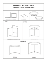
Rear Wheel
Assembly
Front Wheel
Assembly
M6 x 16mm
Shoulder Bolt
M6 x 20mm
SBHCS
Parts & Tools Needed:
Front Wheel
Assembly
Rear Wheel
Assembly
4mm T-Handle
Allen Wrench
M6 x 20mm (2)
1. Attach the Front Wheel Assembly to the sewing machine using two M6 x 16mm Shoulder Bolts.
2. Attach the Rear Wheel Assembly using two M6 x 20mm SBHCS.
M6 x 16mm
Shoulder Bolt (2)
1
|Setup & Assembly Wheel Assembly

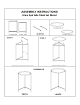
Parts & Tools Needed:
1. Remove the Handle Cover Plate from the
machine by unscrewing the four M6 x 16mm
FCHS screws.
2. Place the Handle Assembly into the slot then
replace the Handle Cover Plate and secure it
in place with the M6 x 16mm FCHS screws
Handle Assembly
3. Insert the handle cables into the plugs. Make
sure the cable connectors are plugged in so
that the Green Stickers are facing up.
4mm T-Handle
Allen Wrench
2
|Setup & Assembly Handle Assembly
M6 x 16
FCHS Screw
Handle
Cover Plate
M6 x 16
FCHS Screw
Handle
Cover Plate
Handle
Assembly
Handle Cable
Connectors
Connector
Leads

Tools Needed:
5mm T-Handle
Allen Wrench
1. Loosen the M8 set screw and lift the handles
until they are at a comfortable angle, then
retighten the set screw.
2. Loosen the Clamp Assembly and rotate the
handle until it is in the desired position, then
retighten the Clamp Assembly.
3. Repeat step 2 for the other handle.
3
|Setup & Assembly Handle Adjustment
M8 Set
Screw
Clamp
Assembly

Parts & Tools Needed:
1. Make sure that the Display Cable goes
up through the gap between the Display
Clip and the OLED Display and twist it 180
degrees so that the Display Cable Connector
is positioned as shown above
2. Install the display by pressing the display clip
into the slot until it clicks into place, then
plug the Display Cable Connector into the
Display Cable Port.
M6 x 10mm
SBHCS (2)
Thread Mast
Assembly
OLED Display
and Cable
4mm T-Handle
Allen Wrench
3. Attach the Thread Mast Assembly by
screwing it to the side of the machine using
two M6 x 10mm SBHCS
4
|Setup & Assembly Display & Thread Mast Setup
OLED
Display
Display
Cable
Connector
M6 x 10mm
SBHCS
Thread
Mast
Assembly
Twist the
Cable 180
Degrees
Display
Cable Port
Display
Clip
OLED
Display
Display
Cable
Display
Cable
Connector
Display
Clip

Tools Needed:
1. Place the Sewing Machine on to the quilting
frame on the bottom carriage.
4mm T-Handle
Allen Wrench
2. Loosen the set screws on the Wheel Supports and adjust them by sliding them to the proper
spacing to fit the top carriage, then retighten the set screws.
5
|Setup & Assembly Carriage Adjustment
Wheel
Support
Set Screw
Bottom
Carriage
Wheel
Support
Wheel
Support
Wheel
Support
Set Screw

Parts & Tools Needed:
Plastic Base - RightPlastic Base - Left
M6 x 10mm
SBHCS (4)
4mm T-Handle
Allen Wrench
1. Attach the Plastic Base to the end of the Wheel Assemblies using M6 x 10mm SBHCS.
2. Repeat the same process for the other side.
6
|Setup & Assembly Plastic Base Assembly
M6 x 10mm
SBHCS
Left Plastic
Base

1. Remove the Left Rear Wheel (see orientation
diagram above) from the Sewing Machine
and the bottom carriage using the 4mm allen
wrench. Set the wheels aside for now.
2. Check the encoders to ensure that they
contain all of the necessary parts and that
the lock collar is loose.
4mm T-Handle
Allen Wrench
Upper Encoder
(Silver Spring)
Lower Encoder
(Black Spring)
2mm T-Handle
Allen Wrench
Parts & Tools Needed:
7
|Setup & Assembly Encoder Assembly
Shoulder Spacer
Washer
Wheel Spacer
Plastic Stop
M6 x 16mm
SBHCS
Wheel
Lock Collar
Front
Right
Left
Rear
The encoders
must be installed
in the left rear
position of the
top and bottom
carriages
Orientation Diagram

3. Place one of the wheels onto the Upper
Encoder and screw it onto the left rear
position on the Sewing Machine.
5. Twist the lock collar on the Upper Encoder to
the right and tighten the set screw using the
2mm Allen wrench to tension the encoder.
4. Place the remaining wheel onto the Lower
Encoder and screw it in to the rear left
position of the Bottom Carriage.
6. Twist the lock collar on the Lower Encoder to
the left and tighten the set screw using the
2mm Allen wrench to tension the encoder.
Lower Encoder (Black Spring)
Lower Encoder (Black Spring)Upper Encoder (Silver Spring)
Upper Encoder (Silver Spring)
8
|Section Title Subtitle|Setup & Assembly Encoder Assembly
Upper
Encoder
(Silver Spring)
Wheel
Lower Encoder
(Black Spring)
Wheel
Twist Lock Collar
to the Right
Tighten the Lock
Collar Set Screw
Tighten the Lock
Collar Set Screw
Twist Lock Collar
to the Left
Lower Encoder
(Black Spring)
Upper Encoder
(Silver Spring)

Parts Needed:
Short Encoder
Cable
Long Encoder
Cable
1. Plug the Short Encoder Cable into the Upper
Encoder. The tab on the cables plug should
face away from the encoder.
9
|Section Title Subtitle|Setup & Assembly Encoder Cables
Encoder
Encoder
Foot Pedal
Quilt Motion Control
USB Connector Port
Short Encoder
Cable
Upper Encoder
(Silver Spring)

3. Plug both encoder cables into the encoder
ports on the side of the sewing machine.
Make sure all cables are firmly plugged in.
2. Plug the Long Encoder Cable into the Lower
Encoder. The tab on the cables plug should
face away from the encoder.
10
|Section Title Subtitle|Setup & Assembly Encoder Cables
Long Encoder
Cable
Encoder Port
Encoder Cables
Lower Encoder
(Black Spring)

Threading Diagram
Needle Diagram
11
|Setup & Assembly Threading The Sewing Machine
Scarf
Eye
Point
Shaft
Shank
Front View Side View
Groove
3. Dual Thread
Tension Guide
1. Thread Cone
and Thread Stand
2. Thread
Mast
4. Small Thread
Tensioner
5. Thread Guide
9. Thread Guide
7. Thread Guide
6. Large Thread
Tensioner
8. Take Up Bar
11. Eye of the Needle
10. Needle Bar Eyelet
/