Page is loading ...

Document: Date
Created By: ECO#
LPN00530X0001A0_A
TMT 008328
INSTALLATION INSTRUCTIONS
LED TRACK HEAD
E-KCN SERIES
2017-9-25
www.e-conolight.com | 888.243.9445 | FAX: 262.504.5409
1. To install track xture into lower circuit of two-circuit track,
follow directions for single circuit installation.
2. To install track xture into upper circuit of two-circuit track,
raise the Brass Contact labeled “P” by grasping Contact with
needle nose pliers and pulling up into position. See
Figure 3.
3. Insert Contact Support by tipping and positioning it under the
“P” Contact. See Figure 3. Snap Contact Support in place.
NOTE: Once the contact support is in place, make sure the
“P” contact is fully seated in the support by using the needle
nose pliers to push the “P” contact into place.
4. Refer to instructions 1-3 under “Fixture Installation on Single
Circuit Track” section.
CAUTIONS
DIMMING INFORMATION
For a list of approved dimmers visit www.e-conolight.com
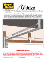
1. Insert Brass Contact on top of Track Adaptor into the Track
Channel. See Figures 1 and 3.
2. Rotate the Track Adaptor 90° so that the Indicator Arrows
point toward the Polarity Groove once installed. See
Figure 2. Pull Adaptor Latch down as you rotate Track
Adaptor in order for Latch to clear track edge and allow it
to snap into place in the track.
3. To remove or relocate track xture location, pull Adaptor
Latch down, rotate the Track Adaptor 90° away from the
Polarity Groove and remove.
FIGURE 1
Notes:
1. All E-conolight Track sections are manufactured with a
Polarity Groove.
2. All E-conolight Track fixtures are manufactured with
Indicator Arrows designed to point toward the Polarity
Groove once installed. See Figures 1-2.
3. E-conolight Track fixtures are UL® Classified for use
with E-conolight E-K1 and E-K2 Series, Ruud T1 and
T2 Series, and Juno® (not affiliated with E-conolight or
Ruud) T and TU Series track systems only.
4. All E-conolight Track fixtures are supplied with a Contact
Support to convert fixture from Single Circuit installation
to Two Circuit Installation. See Figure 3
FIXTURE INSTALLATION – SINGLE CIRCUIT
TRACK
FIXTURE INSTALLATION – TWO CIRCUIT
TRACK
Track Adapter
Indicator Arrows
Luminaire
Movable Brass
Contact “P”
FIGURE 2
FIGURE 3
Plastic
Insulator
Polarity
Groove
Copper
Conductors
Aluminum Track
Extrusion
Contact
Support
IMPORTANT SAFEGUARDS
When using electrical equipment, basic safety precautions should
always be followed including the following:
READ AND FOLLOW ALL SAFETY
INSTRUCTIONS
1. DANGER- Risk of shock- Disconnect power before installation.
DANGER – Risque de choc – Couper l’alimentation avant
l’installation.
2. This luminaire must be installed in accordance with the NEC
or your local electrical code. If you are not familiar with these
codes and requirements, consult a qualied electrician.
Ce produit doit être installé conformément à NEC ou votre code
électrique local. Si vous n’êtes pas familier avec ces codes et
ces exigences, veuillez contacter un électricien qualié.
3. Min 90°C supply conductors.
Les fils d’alimentation 90°C min.
4. Wait until xture has cooled down before installing or servicing
the xture.
5. Please read and understand all instructions thoroughly before
installing any part of the Track system.
SAVE THESE INSTRUCTIONS FOR
FUTURE REFERENCE

Document: Date
Created By: ECO#
LPN00530X0001A0_A
TMT 008328
INSTALLATION INSTRUCTIONS
LED TRACK HEAD
E-KCN SERIES
2017-9-25
www.e-conolight.com | 888.243.9445 | FAX: 262.504.5409
BEAM SPREAD ADJUSTMENT
1. To adjust beam spread of xture rotate section of xture
head closet to lens of the xture. See Figure 4.
FIGURE 4
Rotate To Adjust
Beam Spread
CAUTION: Changes or modications not expressly approved could
void your authority to use this equipment.
This device complies with part 15 of the FCC Rules. Operation is
subject to the following two conditions: (1) This device may not cause
harmful interference, and (2) this device must accept any interference
received, including interference that may cause undesired operation.
This equipment has been tested and found to comply with the limits
for a Class A digital device, pursuant to part 15 of the FCC Rules.
These limits are designed to provide reasonable protection against
harmful interference when the equipment is operated in a commercial
environment. This equipment generates, uses, and can radiate radio
frequency energy and, if not installed and used in accordance with
the instruction manual, may cause harmful interference to radio
communications. Operation of this equipment in a residential area
is likely to cause harmful interference in which case the user will be
required to correct the interference at his own expense.
CAN ICES-005 (A)/NMB-005 (A)
FCC NOTICE
/