Page is loading ...

Wayne-Dalton Corp.
P.O. Box 67 Mt. Hope, OH 44660
(888) 827-3667
www.wayne-dalton.com
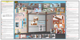
Model 3982 idrive™ Extension Spring Kit.
Use these instructions to install the extension spring kit with idrive™ Models: 3660-372/ 3661-372/ 3662-372/ 3760-372
Covered under one or more of the following U.S. patents: D413,579;D466,141; D472,568; D472,910;D473,573; D473,574;
D474,215; D505,393; D517,580; 5,929,580; 6,078,249; 6,145,570; 6,164,014; 6,253,824; 6,263,947; 6,325,134; 6,326,751;
6,326,754; 6,401,792; 6,561,255; 6,561,256; 6,568,454; 6,588,156; 6,605,910; 6,667,591; 6,739,372; 6,845,804; 6,851,465;
6,873,127; 6,880,609; 6,903,650; 7,053,571; 7,061,197; 7,075,256; 7,109,677; 7,123,128; 7,143,804; 7,173,389; 7,173,514;
7,173,516; 7,183,732; 7,190,266; 7,193,502; 7,207,142; 7,211,975. other U.S. and foreign patents pending
© Copyright 2007 Wayne-Dalton Corp. Rev1
Part No. 306436
Important Notice!
Use these instructions instead of the manual included with your idrive™. Read
the enclosed instructions carefully before installing/operating this garage door
opener. Pay close attention to all warning labels and notes. This manual should
be attached to the wall in close proximity to the garage door opener.
7/6/2007
EXTENSION
Installation Instructions and Owner’s Manual

Table of Contents
System Requirements 2.
Important Safety Instructions 3.
Package Contents 4. - 5.
Tools Needed 6.
Available Accessories 6.
idrive™ Retro-fi t Installation 7.
Extension idrive™ Installation 7. - 14.
Pre-Operation Installation 15. - 29.
Operation 30. - 32.
Maintenance 33.
Troubleshooting 34. - 35.
Warranty 36.
Customer Service Number 36.
System Requirements
FCC and IC Statement
FCC Regulatory Information:
This device complies with Part 15 of the FCC Rules. Operation is subject to the following two
conditions: (1) this device may not cause harmful interference, and (2) this device must accept any
interference received, including interference that may cause undesired operation.
IC Regulatory Information:
Operation is subject to the following two conditions: (1) this device may not cause interference,
and (2) this device must accept any interference, including interference that may cause undesired
operation of the device.
After installation is complete, fasten this manual near garage door. Perform monthly maintenance (see Mainte-
nance section page 33 of your idrive™ Installation Instructions and Owners Manual) and periodic checks, as
recommended.
NOTE:
Extension spring kit, model 3982 is designed for garage doors 7’-0” wide to 10’-0” wide and up to 8’-0”
high.
WARNING To reduce the risk of severe injury or death,
use this kit only with the following openers:
idrive™ Models 3660-372, 3661-372, 3662-372, 3760-372 or 3760N-372 can be
installed on a garage door with an extension spring counterbalance system and
standard lift track, ONLY when installed with the Infrared Safety Sensors Accessory;
Model 3965.
idrive™ Model 3660-372, 3661-372, 3662-372, 3760-372 & 3760N-372 can be
installed on a garage door with an extension spring counterbalance system and
standard 6” low headroom track, ONLY with the Low Headroom Kit, Model 3980 (not
included).
2

3
IMPORTANT SAFETY INSTRUCTIONS FOR
INSTALLATION AND USE
IMPORTANT SAFETY INSTRUCTIONS FOR
INSTALLATION AND USE
READ AND FOLLOW ALL
INSTALLATION INSTRUCTIONS.
Do not connect the opener to a
power source until instructed to do
so.
Where possible, install the opener
seven feet or more above the fl oor.
Mount emergency release six feet
above the fl oor.
Locate the wall station: (a) within
sight of door, (b) at a minimum
height of fi ve feet, so small children
cannot reach it, and (c) away from
all moving parts of the door.
After installing the opener, the door
must reverse when it contacts a
1-1/2” high object (or 2 x 4 board
laid fl at) on the fl oor.
WARNING: INCORRECT
INSTALLATION CAN
LEAD TO SEVERE OR
FATAL INJURY. FOLLOW
INSTRUCTIONS.
WARNING: IT IS VITAL
FOR THE SAFETY OF
PERSONS TO FOLLOW
ALL INSTRUCTIONS. SAVE
THESE INSTRUCTIONS.
Install the entrapment warning
label next to the wall station in
a prominent location. Install the
emergency release marking on or
next to the emergency disconnect.
Remove all ropes and remove
or make inoperative all locks
connected to the garage door before
installing the opener.
Do not wear rings, watches or loose
clothing when installing or servicing
a garage door system.
Install only on a properly balanced
garage door. An improperly
balanced door could cause severe
injury. Have a qualifi ed service
person make repairs to cables,
spring assemblies, and other
hardware before installing the
opener.
NOTE: This equipment has been tested and found to comply with limits for a Class B digital device,
pursuant to Part 15 of FCC Rules. These limits are designed to provide reasonable protection against
harmful interference in a residential installation. This equipment generates, uses and can radiate ra-
dio frequency energy and, if not installed and used in accordance with these instruction, may cause
harmful interference to radio communication; however, there is no guarantee that interference will not
occur in a particular installation. If this equipment does cause harmful interference to radio or televi-
sion reception, which can be determined by turning equipment off and on, user is encouraged to try to
correct interference by one or more of the following measures: Reorient or relocate receiving antenna.
Increase separation between equipment and receiver. Connect equipment into an outlet on a circuit
different from that which receiver is connected. Consult your dealer or/and experienced radio/television
technician for help. WARNING: Changes or modifi cations to this unit not expressly approved by party
responsible for compliance could void user’s authority to operate this equipment.
Installation and wiring must comply
with local building and electrical
codes. Connect power cord to a
properly grounded outlet. Do not
remove the ground pin from power
cord.
Wear safety glasses for eye
protection when installing or
servicing the opener or door.

(2) 1/2-13 Lock Nut
(4) 1/2” Flat Washer
(2) 1/4-20 x 9/16”
Track Bolt
(2) 1/4-20
Flange Hex Nut
(4) 3/8-16 x 3/4” Truss
Head Bolt
(4) 3/8-16
Hex Nut
(2) 1/2-13 x 2” Socket Head Cap Screw
(2) Snap Buttons
(2) Drum Shafts
(2) 3-Hole Clip
(2) Large S-Hook
Cable Loop Tool
(4) spacers
(2) 5/16” x 1-5/8” Hex Head Lag Screw
Hardware Kit: 3982 idrive™ Extension Spring Kit
Photoelectric Safety Sensors
W/Hardware
(3) Cam Tubes
Flag Brackets
LH.
RH.
Cable/Drum
Assembly
LH.
RH.
Drum Wrap Set
LH.
RH.
Package Contents: 3982 idrive™ Extension Spring Kit
Grease Packet (1)
Owners Manual
4

5
6’ Power Cord (1)
Three-button
Transmitter (2)
Entrapment Label
Wall Station Assembly
Jumpers (3)
Disconnect
Handle (1)
Handle Bracket (1)
“S” Hook (1)
Disconnect Cable (1)
Emergency
Disconnect Label (1)
1/4 x 2” Hex Head Lag Screws (2)
#6-20 x 1/2” Phillips Pan
Head PL Screw (1)
(for disconnect handle)
#6 x 7/8” Phillips Pan
Head Screws (4)
Cable Clips (4)
Lock Arm Assembly
Opener
Support
Bracket
1/4 x 1-1/2” Hex Head Lag Screws (4)
#6-32 x 3/4” Phillips
Pan Head Screw (1)
(For Light Fixture)
M5 x .8 x 12 Phillips
Pan Head Screw (1)
(For Lock Arm)
idrive™ Package Contents:
idrive™ Hardware Kit:
Owners Manual
Light Fixture Assembly
w/ Screw & Diffuser
Wall Station
Reference Label

Tools Needed:
Deluxe Wireless Light Kit
Model no: 3950-ULDRE
Part no: 302097
6
Infrared Safety Sensor
Model no: ML2
Part no: 301674
Power Drill
Tape Measure
Step Ladder
7/16” Wrench
1/2” Wrench
9/16” Wrench
3/4” Wrench
Phillips Head
Screwdriver
7/16” Socket Driver
3/32” Drill Bit
7/16” Socket
1/2” Socket
9/16” Socket
3/4” Socket
Pencil
5-Button Wall-Station RF
Transmitter
Model no: 3975
Part no: 302090
3-Button Mini RF Trans-
mitter
Model no: 3973
Part no: 302083
Keyless Entry RF
Transmitter
Model no: KEP2
Part no: 302078
1/8” Drill Bit
Ratchet
Locking Pliers (2)
Low Headroom Kit
Part no: 302883
Power Cord Extender
Model no: 3960M, Part no: 302616
Available Accessories: For idrive™
Level
Safety Glasses
Flat Head Screw-
driver
3/8” Hex Wrench

7
Step 3: Lifting Cable Loop
Extension idrive™ Installation
idrive™ Retro-fi t Installation
Step 2: Remove Front Sheave
Disassemble the existing front cable sheaves. Typi-
cally the front sheave is secured with a bolt and nut to
the horizontal angle. Repeat for other side. (NOTE:
It may be helpful to refer to the original garage
door’s owner’s manual for removing parts from
the original door.)
Step 1: Extension Spring Relief
Raise the door to the fully open position and clamp locking pliers to the back legs of both vertical tracks, below
the bottom rollers to prevent the door from falling (see Fig. 1). By opening the door, you release most of the
spring tension. Carefully unfasten the S-hook from the horizontal angle. Remove the counterbalance cable.
Leave extension spring with it’s sheave installed. Repeat for the other side.
WARNING COUNTERBALANCE SPRING TENSION MUST BE RELIEVED BEFORE RE-
MOVING ANY HARDWARE. A POWERFUL SPRING RELEASING IT’S ENERGY SUDDENLY CAN
CAUSE SEVERE, EVEN FATAL INJURY.
NOTE: Only remove springs when door is in the up position and visegrip pliers are attached to the
track.
LOCKING
PLIERS
Locate the bottom bracket at the lower edge of the bottom
section. The lift cable will be attached to the brackets
milford pin. Measure the diameter of the head of the pin
and record the measurement. Locate the drum assemblies
provided with the kit. They will have a cable attached
with a loop formed on the end of the cable.
Locate the cable loop tool and install the loop over the
shape that corresponds to the milford pin head size you
measured. Use the larger size if the milford pin head size
is greater than or equal to 1/2”, and the smaller size if the
diameter is less than 1/2”. With the cable installed onto
the tool, pull the cable tight, forming it around the loop
tool. Remove the cable from the tool while holding the
cable so it does not slip in the crimp sleeve. Place the
crimp sleeve on a hard surface and using a hammer, hit
the crimp sleeve until it is squeezed tightly around the cable. Verify the loop has been set securely by pulling
on the loop. Repeat for the other cable. Set the drum/cable assemblies aside until needed.
WARNING FAILURE TO CRIMP SLEEVE SECURELY TO CABLE, CAN CAUSE CABLE
TO SLIP OUT, ALLOWING DOOR TO FALL DURING OPERATION, RESULTING IN SEVERE OR
FATAL INJURY.
LOOP
TOOL
CRIMP SLEEVE
PULL LIFTING CABLE
TIGHT SNUGGING THE
CABLE TO SIZE AROUND
THE FIXTURE
MILFORD PIN
BOTTOM
BRACKET
CAREFULLY REMOVE THE “S” HOOK AND COUNTERBALANCE
CABLE (REPEAT FOR THE OTHER SIDE)
ATTACH LOCKING PLIERS TO BACK LEG OF
TRACK BELOW ROLLER (BOTH SIDES)
FRONT CABLE
SHEAVE
HORIZONTAL
ANGLE
BOTTOM DOOR
SECTION
NUT
SAFETY
CABLE
(LEAVE IN-
STALLED)
BOTTOM
ROLLER
FIG. 1

Step 4: Flag Bracket Installation
There are two fl ag brackets (left
and right) provided. The right side
bracket has an extended fl ange at the
top. Align the left hand fl ag bracket
to the existing left fl ag angle, so the
top fl ange will be located to the top
edge of the existing fl ag angle.
Identify two locations that will al-
low the 3/8” bolts to go through both
the fl ag bracket and the existing fl ag
angle.
NOTE: In some instances there
may not be any holes in the existing fl agangles to mount the fl ag brack-
ets. It will be necessary to drill two 3/8” dia. holes that will allow the
3/8” bolts to go through both the existing fl ag angles and the new fl ag
brackets. Once the holes are drilled proceed with the installation of the fl ag brackets as
shown in step 4.
Insert the 3/8” bolts into the previously identifi ed slot in the fl ag bracket, insert a spacer onto the bolt and posi-
tion the fl ag bracket to the existing fl ag angle. Attach the 3/8” nut and tighten. Secure the second bolt, spacer
and nut in the same manner. Make sure that the fl ag bracket is parallel with the existing fl ag angle.
IMPORTANT! Flag brackets must be level and plumb. Secure the top of the fl ag bracket with a 5/16” lag
screw in the slot provided. Repeat the procedure for the right hand bracket.
NOTE: Right and Left hand is determined from inside the garage, looking out.
RIGHT HAND
FLAG BRACKET
LEFT HAND
FLAG BRACKET
FLAG
BRACKET
FLAGANGLE
(2) SPACERS
(2) 3/8-16 X 3/4”
TRUSS HEAD
BOLTS
(2) 3/8”
NUTS
5/16 X 1-5/8”
LAG SCREW
BRACKET
INSTALLED
Step 4A: Track Width
Conformation
For the extension spring torsion
tube to install correctly it is neces-
sary that the distance between the
fl ag angles be correct. Measure the
distance between the existing fl ag
angles. The dimension needs to be
the width of the door + 3-1/2”. If
this is not what the track is set to,
then you must adjust the track so
that the mounting brackets meet
the requirment.To move the track it
may be necessary to loosen the bolts
in the fl ag angles and the brackets
mounting it to the jamb. Set the
track so it is 1-3/4” from the edge
of the door on both sides. Reinstall bolts in the jamb brackets and fl ag angles. Recheck dimensions before go-
ing to the next step.
8
DOOR WIDTH + 3-1/2”
DOOR WIDTH
1-3/4”
1-3/4”
EXTENSION SPRING
FLAG BRACKETS
EXISTING
FLAG ANGLES
DRILL (2) 3/8” DIA.
HOLES TO MATCH
SLOTS IN FLAG
BRACKETS

9
Step 5: Cable Drum Installation
NOTE: Do not remove shrink wrap from cable
drums until instructed to do so.
Cable drums are right and left. Be sure to check the
identifi cation on each drum to make sure the correct
drum is installed on its corresponding side.
Apply grease to both sides and outer diameter of the
fl ange of the drum shaft.
Insert the 1/2-13 x 2” socket head cap screw into the
drum shaft. Then insert the screw and shaft into the
drum so that the screw threads and drum shaft are
showing out past the drum bearing.
Install the drum/shaft/screw assembly into the 3/4”
hole in the fl ag bracket. Be sure the end of the shaft
is inserted into the hole in the fl ag angle.
Secure assembly with a 1/2” washer and 1/2”
lock nut.
Check to make sure the drum will rotate freely
on the shaft. If not, loosen 1/2” lock nut until the
drum is free to rotate. Repeat for opposite side.
CABLE DRUM
DRUM SHAFT
1/2-13 X 2” SOCKET
HEAD CAP SCREW
1/2-13 X 2” SOCKET
HEAD CAP SCREW
APPLY GREASE
TO DRUM SHAFT
FLANGE
DRUM ASSEMBLY
(SHRINK WRAPPED)
1/2” WASHER
1/2” LOCK
NUT
3/4” HOLE
FLAG
BRACKET
DRUM SHAFT
Locate the end of the lifting cable where the custom loop
was made earlier in the instructions. Carefully pull the
cable, bringing the loop to the milford pin located in the
bottom bracket on the edge of the bottom section. Secure
the cable loop around the milford pin, making
sure the loop is over the head of the milford pin
and around the smaller diameter. Repeat for the
other side.
LIFTING
CABLE
Step 6: Bottom Bracket Lifting Cables
MILFORD PIN ON
BOTTOM BRACKET

NOTE: The door lifting cable and the extension spring cable are
wrapped oppositely on the drum.
Take the end of the extension spring cable, thread it through and
around the sheave located on the extension spring, then bring the
cable to the front of the track.
COUNTERBALANCE
CABLE ON DRUM
GROOVES
COUNTERBALANCE CABLE
ON SPRING SHEAVE
SHEAVE
CABLE DRUM
SECURED TO FRAMING
MEMBERS
S-HOOK
3-HOLE
CLIP
RELOCATING S-HOOK OR ADJUST-
ING THE CABLE IN THE 3-HOLE CLIP
ADJUST CABLE SO THAT
SPRING STRETCHES 1”, BY
Step 8: Extension Spring Counterbalance
10
Step 7: Drum Wrap Installation
NOTE: Right and Left hand is determined
from inside the garage, looking out.
Drum wraps are right and left. Take the
extension spring cable and unroll it, thread
the free end of the cable through the
rectangular window of the drum wrap.
Position the drum wrap as shown
LEFT HAND
DRUM WRAP
CABLE
DRUM
1/4-20 X 9/16”
TRACK BOLT
1/4-20
FLANGE NUT
FLAG
BRACKET
RECTANGULAR
WINDOW
EXTENSION
SPRING CABLE
DRUM WRAP INSTALLED
SECURE COUNTERBALANCE
CABLE WITH S-HOOK AND 3-
HOLE CLIP
EXTENSION SPRING
COUNTERBALANCE
CABLE
CABLE DRUM
REVERSE
ANGLE

Now that the counterbalance system is installed to the
garage door, remove the locking pliers and carefully
lower the door to the fully closed position. Be sure
the door descends uniformly by pulling the door down
from the center of the door and using correct gripping
points, such as a lift handle or lock handle.
WARNING TO AVOID SEVERE IN-
JURY DO NOT PLACE FINGERS OR HAND
BETWEEN SECTION JOINTS.
Once the door is closed, measure the spring length on
both springs and verify the spring tension length is the
same for both springs. If they are not, raise the door,
re-attach locking pliers and repeat the CABLE ADJUSTMENT process in Step8.
IMPORTANT! Do not try to adjust springs while the door is in the closed (Down) position.
Ensure that the safety cables installed on your door are not tangled with the extension spring cables. Contact
a professional garage door service technician if safety cables are not installed through each of the extension
springs on your door.
Step 10: Lower the Door
Step 9: Safety Cable Installation
SAFETY CABLE
EXTENSION SPRING
3 HOLE CLIP
REAR SUPPORT
SHEAVE
11
Attach the 3-hole clip as shown. Insert the S-hook into the 3-hole clip. Pull the
cables taut ensuring the cable is on the sheave. Connect the cable to the hori-
zontal angle. Repeat Step 8 for the opposite side of the door.
After the counterbalance cables are installed on both sides of the track, lift the
drum wrap to remove the shrink wrap from the cable drums. Re-insert the drum
wrap and match the hole in the drum wrap with the hole in the fl ag bracket.
Secure the drum wrap to the fl ag bracket using (1) 1/4-20 x 9/16” track bolt and
1/4-20 fl ange nut (see Fig.7). Repeat for the other side.
SPRING ADJUSTMENTS: Adjust the counterbalance cables so that there is
no more than 1” of spring stretch. This is done by adjusting the cable in the 3-
hole clip and/or moving the S-hook to another location on the horizontal angle.
Be sure that the left and right side counterbalance cables are adjusted to provide
the same amount of spring pre-tension on each side.
3-HOLE
CLIP
TIE CABLE
THROUGH THE (2)
SMALLER HOLES
S-HOOK
CABLE
SPRING TENSION
EQUAL ON BOTH SIDES

12
Locate the (3) pieces of cam shaped tube (Torque Tube).
Notice that one piece is smaller and will fi t inside the other two
pieces.
NOTE: Right and left hand are always determined from inside
the garage looking out.
Locate the idrive™ opener in the operator box. Look into the
opener’s left side to ensure the left hand bearing and the internal
(black) sleeve are aligned with the torque tube profi le. Once
aligned, slide the opener onto the smaller piece of tubing.
IMPORTANT! To avoid damage, tube must be assembled enter-
ing left side of opener and exiting right side.
NOTE: Hold the opener by the main
body. Do not hold by the motor.
As the right end of the torque tube en-
ters the internal (black) sleeve, rotate
the opener back and forth slightly to
help aid alignment.
NOTE: Do not force the opener onto
the tube if misalignment occurs.
Continue sliding the opener onto the
torque tube. Align the right hand bear-
ing with the torque tube and slide the
opener completely onto the torque
tube until the torque tube exits the
opener right hand bearing. Continue
sliding the opener to the center of the
torque tube.
Install the snap buttons into each end of the tube.
Take the two larger torque tubes and slide one over each end
of the smaller torque tube. Be sure that the end with the 3
sets of holes is toward the opener.
OPENER
SMALL
TORQUE
TUBE
LEFT HAND
BEARING
Step 11: idrive™ Opener/Torque Tube Assembly
TORQUE TUBE
AND BEAR-
ING PROFILES
ALIGNED
SNAP BUTTONS
SMALL TORQUE
TUBE
POWER
CORD
MOTOR
RIGHT HAND
BEARING

Push the outer torque tubes in until they are touching the opener. Be sure that the snap buttons are not engaged
in any of the outer tube holes. This will make the torque tube the shortest in length and allow enough room to
get the tubes into the drums. The torque tube can be adjusted to fi t a door width of 8’ to 10’ in 6” increments.
See fi gure above.
Lift the iDrive™ opener/ torque tube assembly up to the drums. It may be
necessary to disconnect the motor from the torque tube to get the tube into
the drum. To disconnect, pull the cable coming out of the top right hand
side of the opener. This will disconnect the motor and allow the torque
tube to rotate inside the opener. Align one end of the tube to the “cam”
shaped hole in the drum. Once aligned, slide the tube into the
cable drum. Make sure it is all the way into the drum. Now take the op
posite end of the tube and slide it into the other drum. Extending the tube
so that the tube is all the way in both drums. When correct, the snap but-
tons will engage the set of holes for your door width.
13
SNAP BUTTONS
ENGAGED
Locate the spring pad. The spring pad is a vertical running board above the center of the door. Remove
(2) 1/4-20 fl ange nuts from bottom of opener. NOTE: Do not discard fl ange nuts. Place the support bracket
(in idrive™ hardware bag) underneath the opener, to the right side of motor, centered on spring pad. Level
the torque tube to the top of the door section with the idrive™ resting on the support bracket. Once torque
tube is level, secure support bracket to the spring pad with (2) 1/4 x 2” lag screws(operator hardware). Lift and
slide the opener over the support bracket, aligning the mounting studs with the bracket slots. Loosely fasten to
mounting studs with the (2) 1/4-20 fl ange nuts.
NOTE: Do not tighten 1/4-20 fl ange nuts to opener studs
at this time.
Step 12: idrive™ Opener/Torque Tube Assembly Installation
10’-0”
8’-0”
1
2
3
1
2
3
Door
Width
Left Hand
Torque Tube
Right Hand
Torque Tube
8’-0” hole 1 hole 1
8’-6” hole 2 hole 1
9’-0” hole 2 hole 2
9’-6” hole 3 hole 2
10’-0” hole 3 hole 3
LEFT HAND
TORQUE TUBE
RIGHT HAND
TORQUE TUBE
MOTOR
OPENER
SPRING PAD
SUPPORT BRACKET
TORQUE TUBE
PARALLEL AND
LEVEL WITH
TOP OF DOOR
(2) 1/4 X 2” LAG SCREWS
Step 13: Secure idrive™ Opener
MOTOR
OPENER
SPRING PAD
TORQUE TUBE
PARALLEL AND
LEVEL WITH
TOP OF DOOR
(2) 1/4-20 FLANGE HEX NUTS

Attach the loose disconnect cable
(located in opener hardware bag)
to the opener with the S-hook.
Close both ends of the S-hook to
lock assembly together.
Thread the disconnect cable
through the hole in right hand
fl ag bracket and remove all slack
between opener and right hand
fl ag bracket.
Mark a location on the right
jamb, 6 feet above the fl oor to
mount the handle bracket. Align
top of the bracket with the mark.
Fasten bracket to the jamb with
(2) 1/4 x 1-1/2” lag screws. Start the #6-20 x 1/2”screw
into the handle. Thread the disconnect cable through the
top of the handle bracket and then the handle. Locate
the handle in full upper position of handle bracket. Then
remove all cable slack between the opener and the top
of the handle bracket. Tighten #6-20 x 1/2” screw into
the handle until snug, and then tighten screw an addi-
tional 1 to 1-1/2 turns to secure cable to handle. Trim
off excess cable from bottom of the handle.
NOTE: It is recommended that 1/4” lag screw loca-
tion be pilot drilled using 1/8” drill bit.
CAUTION: Pull cable only enough to remove the
cable slack. Pulling the cable more could cause opener
to disconnect from the torque tube.
Apply emergency disconnect label next to the mounted
bracket. Use mechanical fasteners if adhesive will not
adhere.
Using the emergency disconnect, pull disconnect handle
downwards and place it in the manual door operated
position. Use disconnect label for reference. Motor
will be rotated 90° from its packaged position.
NOTE: If motor does not pivot 90°, Refer to trouble-
shooting pages 34 and 35 of the iDrive™ Instructions
and Owner’s Manual.
14
Step 14: Disconnect Installation
DISCONNECT
CABLE
S-HOOK
RIGHT HAND
FLAG BRACKET
OPENER
HANDLE
BRACKET
#6-20 X 1/2”
1/4 X 1-1/2”
LAG SCREW
MOUNTED
BRACKET
EMERGENCY
DISCONNECT
CABLE
CABLE
HANDLE
MANUAL DOOR OPERATED POSITION
(To bottom
of door)
6’

Step 15: Wall Station Installation
15
Locate a convenient place to mount wall station within
sight of the garage door. To keep wall station out of the
reach of children, measure at least fi ve feet up from the
fl oor and secure wall station base into wood wall fram-
ing using (2) phillips head screws. Use 2 of 3 holes
that best align with wood framing. Use anchors (not
included) when fastening to drywall or concrete.
CAUTION: Over tightening screws into wood could
deform plastic base and interfere with circuit board
snaps.
NOTE: Pilot drill mounting holes using a 3/32”
(3mm) bit.
Insert bottom of circuit board behind bottom snap of
wall station base. Pivot circuit board up and snap into
place. For best results, press on circuit board between
battery terminals.
Insert battery onto circuit board being careful to match
(+) positive battery marking with (+) circuit board
marking. Align wall station cover/button assembly
with base. Press cover assembly over base until cover
CIRCUIT
BOARD
BOTTOM
SNAP
PRESS HERE
BATTERY TERMINALS
WALL STATION
REFERENCE LABEL
ENTRAPMENT
LABEL
BASE
COVER
ASSEMBLY
snaps into place. A uniform seam between the cover
and base indicates a proper installation.
Apply wall station reference label and entrapment label
in a convenient location next to the wall station.
(2) PHILLIPS HEAD
SCREWS
Pre-Operation Installation
ALTERNATE SCREW LOCATION

NOTE: Skip this step if installing only one idrive™ opener.
Switch Settings: Light Fixture
If installing more than one opener in the same garage, the light fi xtures can be set to function only with a selected
opener. Leaving the light fi xture as is from the factory may cause all light fi xtures to light when any one of the
openers are activated. The opener jumpers and light fi xture switches need to be matched to allow for the opener
to activate a specifi c light fi xture. To adjust switch
location on light fi xture, slide switches on top of light
fi xture housing.
Jumper Settings: Opener
On the right side of the opener, insert jumper(s) provided
in the hardware pack, to match the switch setting of the
light fi xture.
16
Step 16: Multi-Opener/Light Fixture Programming
When the light fi xture switches and the opener jumpers are matched, the light fi xture will respond to its
matched opener.
Jumper Settings
Detail
Opener
Detail
-A- = -A-
-B- = -B-
-C- = -C-
-D- = -D-
Light Fixture
-C-
SWITCH 1 (ON)
SWITCH 2 (ON)
NO JUMPERS
FOR PINS 1 & 2
PIN 1
PIN 2
PINS 1 & 2
SWITCHES
LIGHT FIXTURE
-A-
SWITCH 1 (OFF)
SWITCH 2 (OFF)
(FACTORY
SETTING)
-B-
SWITCH 1 (ON)
SWITCH 2 (OFF)
-D-
SWITCH 1 (OFF)
SWITCH 2 (ON)
-A- -B- -C- -D-
-A- -B-
-C-
-D-
OPENER

NOTE: RECEPTACLE COVER MUST BE INSTALLED
IN-BETWEEN THE LIGHT FIXTURE AND THE CEILING
IMPORTANT! The light is turned on and off by an infrared (IR) signal sent from the opener to the light.
Therefore, the light must be mounted in a location where it can always “see” the front face of the opener.
Locate a duplex receptacle within line of sight of opener, when the door is in the open position.
Disconnect power to the receptacle at the fuse/breaker box before proceeding.
WARNING TO REDUCE THE RISK OF ELECTRICAL SHOCK, THIS EQUIPMENT HAS A
GROUNDING TYPE PLUG, THAT HAS A THIRD
(GROUNDING) PIN. THIS PLUG WILL ONLY FIT
INTO A GROUNDING TYPE OUTLET. IF THE
PLUG DOES NOT FIT INTO THE OUTLET, CON-
TACT A QUALIFIED ELECTRICIAN TO INSTALL
THE PROPER OUTLET. DO NOT CHANGE THE
PLUG IN ANY WAY.
WARNING TO AVOID ELECTRICAL
SHOCK, DISCONNECT POWER TO THE RECEP-
TACLE AT THE FUSE/BREAKER BOX BEFORE
PROCEEDING.
WARNING DO NOT INSTALL THE
LIGHT FIXTURE INTO A RECEPTACLE WITH A
METAL FACEPLATE.
NOTE:
Door must clear light fi xture when the door
is in the open position. There must be no obstruction
between the light fi xture and the opener for light fi xture
to work properly.
CEILING MOUNTING
Remove the center screw in the receptacle cover. Hold-
ing receptacle cover in place, insert light fi xture into
the receptacle that has the ground hole farthest from
center screw hole. Remove center hole plug from light
fi xture to expose the screw hole. Secure light fi xture to
receptacle with a #6-32 x 3/4” phillips pan head screw.
Replace hole plug into the screw hole in the light fi x-
ture.
NOTE: For temperature protection, the hole
plug must be in place prior to using the light fi xture.
Loosen thumb screw and rotate light fi xture’s bottom
section to align the receiving module, side to side,
with the sending LED on the opener. Re-tighten thumb
screw, don’t over tighten. Rotate receiving module to
align, up and down, with the sending LED.
Screw a maximum 75W light bulb into light socket and
snap diffuser into light fi xture. Turn receptacle power
back on at fuse/breaker box. The light should blink
one time when the power is re-established.
NOTE: An accessory power outlet receptacle (600 Watt
Maximum) is provided on the light fi xture.
Step 17: Light Fixture Installation
17
DUPLEX
RECEPTACLE
LIGHT FIXTURE
DIFFUSER
HOLE PLUG
#6-32 X 3/4”
PHILLIPS
PAN HEAD
SCREW
75W (MAX)
LIGHT BULB
(NOT INCLUDED)
ALIGN
RECEIVING
MODULE
AIM AT
IR LED
SENDING IR
LED
OPENER
THUMB
SCREW

WALL MOUNTING
Depending on location, the light
fi xture may need to be adjusted from
its packaged position.
When mounting on a wall parallel
to the opener, rotate the receiver
module inward to a maximum of
90° until the receiver module is
best aligned with the sending LED.
Mount light to a receptacle and align
the receiving module per previous
instructions.
To mount the light fi xture on a wall
perpendicular to the opener, leave
receiving module in the factory
position.
Mount the fi xture to a receptacle
and align receiving module per
previous instructions. Insert hole
plug into the screw hole.
NOTE: For temperature protection, the hole plug must be in place prior to using the light fi xture.
Screw in a maximum 75W light bulb into light socket and snap diffuser into light fi xture. Turn receptacle
power back on at fuse box.
Final alignment of the light fi xture to the opener may be needed once the opener is electrically connected.
18
SOCKET
RECEIVING
MODULE
DIFFUSER
ROTATE 90°
(IF NECESSARY)
#6-32 X 3/4”
PHILLIPS PAN
HEAD SCREW
DUPLEX RE-
CEPTACLE
LIGHT
FIXTURE
HOLE PLUG
LIGHT BULB - 75W
MAX. (NOT INCLUDED)
NOTE: RECEPTACLE COVER MUST BE INSTALLED IN BETWEEN THE
LIGHT FIXTURE AND THE WALL
Light Fixture Installation (Continued)

19
Select a mounting position 5 inches above the fl oor
to center line of wall mounting bracket. The send-
ing and receiving units should be mounted inside the
door opening to minimize any interference by the sun.
However, the sensors should be mounted as close to the
door track or inside edge of the door as possible to offer
maximum entrapment protection. It is very important
that both wall brackets be mounted at the same height
for proper alignment.
The brackets may be temporarily mounted to the jamb
with a 1” fl at head nail (provided) using the small hole
above the slot. Using two 5/16 x 1-1/2” lag screw (pro-
vided), permanently mount the wall mounting brackets
to both door jambs. In some installations it may be nec-
essary to attach a wooden spacer to the wall to achieve
the required clearance.
Attach the “U” brackets to the wall brackets with a
1/4-20 carriage bolt, washer and nut (provided). In-
sert
the bolt from the inside of the “U” bracket and hand
tighten only at this time.
Identify which side of the garage door opening (if any)
is “likely” to be exposed to the sun. Since sunlight
may affect photoelectric sensors, you should mount the
sending unit (not the receiving unit) on the side of the
door opening most exposed to the sun.
NOTE: If wires must be lengthened or spliced into
prewired installation, use wire nuts or suitable con-
nectors.
Attach the sending and receiving units to the “U” brack-
ets by inserting their tabs into the respective holes.
Step 18: Photoelectric Safety Sensor Installation
NAIL
WALL
MOUNTING
BRACKET
NUT
WASHER
1/4-20 X 1/2”
CARRIAGE BOLT
(1) 5/16 X 1-1/2”
LAG SCREWS
5”
“U”
BRACKET
RECEIVING UNIT
SENDING UNIT
HAS NO LED
LIGHT
LED ALIGNMENT
LIGHT
TABS
BOTTOM & TOP
TAB HOLES
BOTTOM & TOP

20
VIEW OF THE OPENER
FROM THE FRONT
JUMPER INSTALLED
ON PINS “PE”
OPENER
SENDING IR LED
Uncoil wires from photoelectric sensors and route
wires up garage wall and along door header towards
the right side of the opener
.
Route wires above torque
tube and tack wires in place with insulated staples (not
supplied). Take care to run wires in a location where
they will not interfere with the operation of the door
and do not staple through wire.
Connect photoelectric sensors to the opener terminal
block in right side of the opener. Separate wire ends
and strip about 1/2” of insulation off each of the wire
ends. Insert a 3/32” (2,5 mm) max. width fl athead
screwdriver into the lower hole #1 of the terminal
block. Twist screwdriver to open wire clamp in up-
per hole #1 of terminal block. Insert both sender and
receiver solid white wires into upper hole #1 until the
wires bottom out and release screwdriver tension. In-
sert both sender and receiver wires (white with black
strip) into upper hole #2 by the same process on lower
hole #2 of terminal block. Once wires are connected
install jumper on to the left most set of pins labeled
“PE”, located on the front of the opener.
IMPORTANT! Keep sender/receiver wires away
from moving members.
Be sure to observe polarity. Pull on external wires to
test for secure connection. Check that the wires are
stapled in place and staples have not cut wire insula-
tion.
INSERT SENDER
WIRES
INSERT
RECEIVER
WIRES
WIRE ROUTING
Photoelectric Safety Sensor
Installation Continued
INSERT WIRES INTO
UPPER HOLES
RIGHT HAND SIDE
VIEW OF OPENER
INSERT SCREW-
DRIVER INTO
LOWER HOLES
SOLID
WHITE WIRES
WHITE WIRES
WITH BLACK
STRIPES
/