Page is loading ...

Mode!No.WESY59840
Seria_No.
WritetheseriaUnumberinthe
spaceaboveforfuturereference,
SedaUNumberDecaU(underseat)
Asamanufacturer,wearecom-
mittedto providingcomptete
customersatisfaction.Ifyou
havequestions,or ifthereare
missingordamagedparts,we
will guarantee complete satis-
faction through direct assis-
tance from our factory.
TO AVOID DELAYS, PLEASE
CALL DIRECT TO OUR TOLL-
FREE CUSTOMER NOT LINE.
The trained technicians on our
customer hot tine wil! provide
immediate assistance, free of
charge.
CUSTOMER HOT LINE:
1°877°992°5999
Mon.=Fd., 6 a.m.=6 p.m. MST
Read all precautions and instruc-
tions in this manuat before
using this equipment. Save this
manual for future reference.

TABLE OF CONTENTS
WARNING DECAL PLACEMENT ............................................................. 2
iMPORTANT PRECAUTIONS ................................................................ 3
BEFORE YOU BEGIN ...................................................................... 4
ASSEMBLY ............................................................................... 5
ADJUSTMENTS .......................................................................... 13
CABLE DIAGRAM ......................................................................... 17
EXERCISE GUiDELiNES .................................................................. 18
ORDERING REPLACEMENT PARTS .................................................. Back Cover
LiMiTED WARRANTY .............................................................. Back Cover
Note: A PART iDENTiFiCATiON CHART and a PART LIST/EXPLODED DRAWING are attached in the center of
this manual. Remove the PART iDENTiFiCATiON CHART and PART LIST/EXPLODED DRAWING before begin-
ning assembly.
WARNING DECAL PLACEMENT
The decals shown here have been
pJaced on the resistance system. If a
decal is missing or iHegibJe, please call
our Customer Service Department toll-
free at 1-877-992-5999, Monday through
Friday, 8 a.m. until 8 p.m. Mountain
Time, to order a free repJacement decal
Apply the decaJ in the location shown.
ieep hands and
ngers clear of
_s area.
®Misuse of this product may result in serious injury.
Read user's manual and follow all warnings
and operating instructions prior to use.
®Do not allow children on or around machine.
* Replace label if damaged, illegible, or removed.
CrossBar by WELDER is a trademark of ICON IP, Inc.

iMPORTANT PRECAUTIONS
AWARNING: Toreducethedskofseriousinjury, readthefollowing important precautions
before using the resistance system.
f. Read all instructions in this manual before
2_
three positions closest to the upright base,
using the resistance system. Use the resist- or while standing on the base plate.
ance system only as described in this manu-
aL f 3. The resistance system is designed to be
used with the included resistance, and the
ff is the re sponsibiHty of the owner to ensure resistance included with a CrossBar by WEI-
that aH users of the resistance system are DER ' Power Pak. Do not use the resistance
adequately informed of all precautions, system with any other type of resistance.
.
The resistance system is intended for home t4.
use onJy. Do not use the resistance system
in any commercial, rental, or institutional set-
ting ....
4. Keep the resistance system indoors, away
(rein moisture and dust. Do not put the t 5.
resistance system in a garage or covered
patio, or near water.
5. Use the resistance system onJy on a (eve)
surface. Cover the floor beneath the resist-
ance system to protect the fJoor.
6. Make sure that aH parts are properly tight-
ened each time the resistance system is
used. Replace any worn parts (mmediateJy.
7. Keep children under 12 and pets away from
the resistance system at aH times.
When adding resistance, both ends of the
resistance bars must rest under the two "U'-
channeJs. Add and remove resistance bars
from the "U _ochannels one resistance bar at
a time.
Keep clear of the area around the "U'-chano
neJs while the resistance system is in use.
Do not add or remove resistance bars from
the "U'ochanneJs while the end of the long
cable is pulled out.
16. AJwaye adjust the resistance bar assembly to
the horizontal position and make sure the
fulcrum knob is secure before using the
resistance system.
17. Make sure the rings on the resistance bars
are pushed against the tray before using the
resistance system.
8. Keep hands and feet away from moving
parts.
9. Always wear atHetic shoes for foot protec-
tion while exercising.
16. The top frame is not designed to be used for
18. if you purchase the optional lat bar, always
disconnect it from the short cables when
performing an exercise that does not require
it.
19. Make sure the storage knob is in place and
fully tightened each time the resistance sys-
puHoup exercises. Do not hang on the top tern is used.
frame.
11. The resistance system is designed to sup-
port a maximum user weight of 306 pounds.
12. Pull on the mowpuJJey cable only while sitting
on the bench or standing on the base plate.
PuH on the high pulley cabJes onJy white sit-
ting on the bench, with the seat in one of the
20. Make sure that the cables remain on the puF
leys at all times, if the eabJes bind as you are
exercising, stop immediateJy and make sure
that the cables are on the pulleys. RepJace aH
cables at least every two years.
21. ff you fee( pain or dizziness while exercising,
stop immediateJy and begin cooling down.
kWARNmNG: Beforebeginnin,thisoranyexerciseprogram,consultyourphysician.This
is especially important for persons over the age of 35 or persons with pre-existing health prob)ems.
Read aH instructions before using. (CON assumes no responsibility for personal injury or property
damage sustained by or through the use of this product.
3

BEFORE YOU BEGIN
Thank you for sebcting the innovative CrossBar by
WELDER''_MAX resistance system, The resistance sys-
tem offers a sebction of stations designed to develop
every major muscb group of the body, Whether your
goal is to tone your body, build dramatic muscle size
and strength, or improve your cardiovascular system,
the resistance system will help you to achieve the spe-
cific results you want,
For your benefit, read this manuaJ carefully before
using the resistance system, if you have questions
after reading this manual, phase call our Customer
Service Department tolPfree at 1°877°992-5999,
Monday through Friday, 6 a,m, until 6 p,m, Mountain
Time (excluding holidays), To help us assist you, please
note the product model number and serial number
before calling, The model number is WESY59840, The
serial number can be found on a decal attached to the
resistance system (see the front cover of this manual),
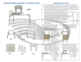
Before reading further, please review the drawing below
and familiarize yourself with the parts that are labeled,
ASSEMBLED
DiMENSiONS:
Height: 82 in,
Width: 66in_
Depth: 80 in,
Fulcrum Knob
Upright
Storage Knob
Top Frame
Lat Tower
High Pulley
Resistance Bars
--"U"oChannel
Backrest
Curl Pad
Curl Bar
Leg
Low Pulley
Base Hate
Seat
Seat Knob
4

This manua! iSdesigned to ensure that the resist-
most PeOPb,However, it iS impo_ant to reanize
that the versatile resistance system has many
parts and that the assembly Process w!Htake
time. Most peopJefind that by setting aside p!enty
d t!me, assembly wi!! go smooth!y:
Before beginning assembly, carefully read the
following information and instructions:
Assembly requires two persons.
Place all parts in a cleared area and remove the
packing materials. Do not dispose of the packing
materials until assembly is completed.
• For help identifying smafl parts, use the PART
IDENTIFICATION CHART, Note: Some small
parts may have been pre-attached for shipping. If
a part is not in the parts bag, check to see if it
has been pre-attached.
Tighten all parts as you assemble them, unless
instructed to do otherwise.
As you assemble the resistance system, make
sure all parts are oriented as shown in the draw-
ings.
The inc!uded AHen wrenches and the follow-
ing tools (not included) are required for assem-
bly:
Two adjustable wrenches
One rubber maltet
One standard screwdriver _.;_
One Phillipsscrewdriver _=C_-_D
Lubricant, such as grease or petroleum jelty,
and soapy water.
Assembly wiii be more convenient if you have a
socket set, a set of open-end or closed-end
wrenches, or a set of ratchet wrenches,
Before beginning assembly, make sure that
you have read and understand the informa-
tion in the box above.
Attach two Plastic Feet r53_ and two Large Plastic
Feet/102/to the Base Ill with four M4 x 16mm
Screws (62/.
Attach the Upright _3} Io the Base (11 with two
MIO x 66mm Carriage Bolts (83L two MIO x
72mm Bolts (64/. and four MIO Nylon Locknuts
/76 as shown. Note: This step will be easier to
complete if the Upright and Base are tipped
on their sides.
62
53_I _,
/ / /
/// //1//_
64
_102
L
_62

AttachaWheel(31)totheoutsideoftheBase(1)
withanMIOx78mmBolt(81),threeMIO
Washers(75),andanMIONylonLocknut(76),
DonotovertightentheLocknut;theWheel
mustbeableto turneasity.
Attach the other Wheel (not shown} in the
same manner.
Orient the Cross Tube (11) as shown, with the
welded tubes at the bottom, Attach the Cross
Tube to the Upright (3) with two MIO x 147mm
Carriage Bolts (73), two MIO Washers (75), and
two MIO Nuts (47),
Press the Front Leg Foot (27) onto the bottom of
the Front Leg (6), Note that the front of the
Front Leg Foot is taller than the back.
Attach the Bench Rail (5), with the hook on the
bottom, to the Front Leg (6) with four MIO x
25mm Button Screws (87),
Lubricate an MIO x 103mm Bolt (66) with grease,
Attach the Bench Rail (5) to the Upright (3) with
the Bolt and an MIO Nylon Locknut (76), Do not
overtighten the Locknut; the Bench Bait must
be able to pivot easily.
Tighten the Storage Knob (30) into the Upright (3)
and the Bench Rail (5),
75
31
81
/
75
47
Welded
11
87
87
Hook
Insert the bolt 76
through this hole
Grease
6

6. 6
Attach the Lat Tower (4) to the Upright (3) with
four M10 x 25mm Button Screws (87), and four
M10 Lock VVashers (103).
Attach the Name Hate (89) to the Lat Tower (4)
with two M4 x 16mm Screws (62).
Attach two Eyebolts (34) to the Top Frame (10)
with two M8 Washers (59) and two M8 Nylon
Locknuts (65). Do not overtighten the Locknuts;
the Eyebolts must be able to rotate freely.
Attach the Top Frame (10) to the Lat Tower (4)
with two M10 x 65mm Button Screws (70), two
M10 Washers (75), and the Top Frame Cover
(93), Make sure that the Eyebolts (34) are ori-
ented as shown in the inset drawing. If they
are not, turn the Top Frame around and reat-
tach it.
Attach the Leg Lever (7) to the Front Leg (6) with
a Long Pin (107) and a Cotter Pin (108),
89
62
103 87
_3
65
"\..
59
34
7O
75
10
65
/
Side View
10.
34
34
107
6
7

9, 9
Attach two 8mm Metal Spacers (97), a 60mm
Metal Spacer (39), and two Bearing Wheeb (46)
to one end of the Seat Carriage (12) with an M8 x
104mm BoUt(60) and an M8 Nybn Locknut (65)
as shown, Make sure the parts are oriented as
shown in the inset drawing; the Seat Knob
(not shown} will not engage the Bench Rail
(not shown} if they are incorrectly oriented.
Do not overtighten the Locknut; the Bearing
Wheels must be able to roll easily.
Attach two Bearing Wheels (not shown} to the
other end of the Seat Carriage (!2) in the
same manner.
10, Attach the Seat Knob (45) to the Seat Carriage
(12) with two M6 x 13mm BoUts(92) and two M6
Nybn Locknuts (69), Make sure that the slot in
the Knob is aligned with the slot in the Seat
Carriage, as shown.
Orient the Seat (13) and the Seat Carriage (12)
as shown, Attach the Seat to the Seat Carriage
with four 1/4" x 16mm Screws (82),
11, Pull out the Seat Knob (45) as far as it will go, and
set the Seat Carriage (12) on the Bench Rail (5),
Loosely attach two 8mm Metal Spacers (97), a
60mm Metal Spacer (39), and two Bearing
Wheels (46) to the center hobs in the Seat
Carriage (12) with two M8 Flange Nuts (19) and
the M8 x 114mm Bolt (57), Make sure that the
serrated edge of the Flange Nuts are against
the Seat Carriage.
While a second person presses down on the Seat
(13), hold the wheel assembly firmly against the
bottom of the Bench Rail (5) and properly tighten
the M8 Flange Nuts (19), Make sure that three
threads are extending past the Nut, and that
the wide sides of aH six Bearing Wheels (46)
are pressed against the Bench Rail.
Engage the Seat Knob (45) into an adjustment
hob in the Bench Rail (5),
10
11
6O
46
39
46
12
second
set of wheels
here
97
Side
82 92
Slots
19
57
13
/
5
12
\
Adjustment
Hob
46
97
39 46
)7
Side
8

12, Attach a Hastic Foot (53) to the Backrest Frame
(15) with an M4 x 16mm Screw (62),
Attach the two Guard Hates (17) to the inside of
the Backrest Frame (15) with four M4 x 16mm
Screws (62),
13, Attach the Backrest (14) to the Backrest Frame
(15) with four 1/4" x 45mm Screws (58),
14, insert the rod on the Backrest Frame (15) into the
slot in the Seat Carriage (12), HoJd the Backrest
Frame vertically over the Seat Carriage and
shale the rod into the sJot, as shown in the
inset drawing.
15, Attach the two lO°pound Short Resistance Bar
Caps (20) to the lO°pound Center Resistance Bar
(44) with two M4 x 12mm Fiat Head Screws (85),
Attach the two lO°pound Resistance Bar Caps
(101) to the lO°pound Removable Resistance Bar
(67), the two 20°pound Resistance Bar Caps (88)
to the 20°pound Removable Resistance Bar (36),
the four 80°pound Resistance Bar Caps (100) to
the two 80°pound Resistance Bars (95), and the
two 40°pound Resistance Bar Caps (79) to the
40°pound Resistance Bar (96) with ten M4 x
12mm Fiat Head Screws (85),
12
13
14
Rod
15
62
17
15
58
\
12
96
88
lO0
9

16, Locate the Fubrum (18) on the Lat Tower (4) (see
the inset drawing), Slide the Tray (35) onto the
rods on the Fubrum, Make sure the Tray is ori-
ented as shown in the drawing.
Set the resistance bars into the Tray (35) in the
following order: the lO-pound Removable
Resistance Bar (67), the 20-pound Removable
Resistance Bar (36), an 80-pound Resistance Bar
(95), the lO-pound Center Resistance Bar (44), an
80-pound Resistance Bar (95), and the 40-pound
Resistance Bar (96), Make sure the indicated
rings are on the side shown and the arrows
point toward the Tray.
Attach the Cover Hate (72), with the edges up, to
the Tray (35) with two M8 x 19mm Button Screws
(86),
17, Locate the Long Cable (80). insert one end of
the Cable through the welded tube on the indicat-
ed end of the Cross Tube (11) and then through a
Swivel Arm (22), if necessary, use the tip of a
screwdriver to pull the end of the Cable out of the
Swivel Arm, Be sure the Cable is on the indicat-
ed side of the welded rod in the Swivel Arm.
insert the Swivel Arm (22) into the welded tube
on the Cross Tube (11), Secure the Swivel Arm
with an M4 x 5ram Screw (104),
Wrap the Long Cable (80) around a 90mm Pulley
(28), Attach the Pulley inside of the Swivel Arm
(22) with an MIO x 42ram Button Bolt (71) and an
MIO Nylon Locknut (76),
18, Wrap the Long Cable (80) around a 90mm Pulley
(28), Attach the Pulley, a Cable Trap (29), an M10
Washer (75), and two Finger Guards (110) to the
indicated M10 x 147mm Carriage Bolt (73) with
an M10 Nylon Locknut (76), Make sure the
Cable Trap and Finger Guards are oriented as
shown.
19, Attach a Pulley Housing (94) to the indicated "U"-
channel on the 10-pound Center Resistance Bar
(44) with an M10 x 128mm Button Bolt (24), two
Pivot Bushings (74), and an M10 Nylon Locknut
(76),
Wrap the Long Cable (80) over a 90mm Pulley
(28), Attach the Pulley inside of the Pulley
Rousing (94) with an MIO x 42ram Button Bolt
(71) and an M10 Nylon Locknut (76),
16
17
18
86
:dges
up
/
Rings on
96
Rods
67
8O
1
71
', 104
76
110
75
29
76
28 110
44
/
76
l
71
24
8O
95
Rod
10

20, Wrap the Long CaMe (80) under a 90mm Pulley
(28) as shown, Attach the Pulley, a CaMe Trap
(29), an MIO Washer (75), and two Finger
Guards (110) to the Upright (3) with an MIO x
127mm Button BoUt(56) and an MIO NyUon
Locknut (76), Note: The Bolt will be packaged
sepearatly for identification. Make sure the
Cabte Trap and Finger Guards are oriented as
shown.
21, Attach a Pulley Housing (94) to the indicated "U"-
channeU on the lO-pound Center Resistance Bar
(44) with an MIO x 128mm Button BoUt(24), two
Pivot Bushings (74), and an MIO NyUonLocknut
(76),
Wrap the Long CaMe (80) over a 90mm Pulley
(28), Attach the Pulley inside of the Pulley
Housing (94) with an MIO x 42mm Button BoUt
(71) and an MIO NyUonLocknut (76),
22, Wrap the Long CaMe (80) around a 90mm Pulley
(28), Attach the Pulley, a CabUeTrap (29), an MIO
Washer (75), and two Finger Guards (110) to the
indicated MIO x 147mm Carriage BoUt(73) with
an MIO NyUonLocknut (76), Make sure the
Cable Trap and Finger Guards are oriented as
shown.
23, Make sure there are no resistance bars under the
"U"-channels on the lO-pound Center Resistance
Bar (not shown), Have a second person pull on
the Long Cable (80) to create slack in the Cable,
Insert the end of the Long Cable (80) through the
welded tube on the indicated end of the Cross
Tube (11) and then through the remaining Swivel
Arm (22), Make sure the CabJe is on the indi-
cated side of the welded rod in the Swivel
Arm.
Insert the Swivel Arm (22) into the welded tube
on the Cross Tube (11), Secure the Swivel Arm
with an M4 x 5mm Screw (104),
Wrap the Long Cable (80) around a 90mm Pulley
(28), Attach the Pulley inside of the Swivel Arm
(22) with an MIO x 42mm Button Bolt (71) and an
MIO Nylon Locknut (76),
2O
21
22
23
11
56
24
Rod
/J
/
/
74
\
71
28
71
29
80

24,LocatetheLegLeverCable(32),whichhastwo
endsthatarethesameUengthandathirdend
thatislonger,
RoutetheUongestendoftheLegLeverCaMe
(32)throughthehoUeintheFrontLeg(6),and
attachit insideofthehoUeintheLegLever(7)
withtheShortPin(109)anda cotterPin(108),
25,Attacha90mmPulley(28)insideofthehoUein
theFrontLeg(6)withanMIOx91mmBoUt(90),
two26mmSpacers(52),twoMIOWashers(75),
andanMIONyUonLocknut(76),Makesurethe
Pulleyis abovetheLegLeverCable(32}.
SHdethetwofreeendsoftheLegLeverCaMe
(32)ontothehookweUdedtothebottomofthe
BenchRail(5),
26,LocatethetwoShortCables(33}.Wraponeof
theCaMesovera90mmPulley(28),Attachthe
Pulleytoa HighPulleyHousing(21)withanMIO
x42mmButtonBoUt(71)andanMIONyUon
Locknut(76),
Repeatthisstepwith theotherShortCable
(33}.
27, SHde the Long Pad Tube (61) through the Front
Leg (6), SHde two Foam Pads (26) onto the tube,
Assemble the two Short Pad Tubes (9} to the
Leg Lever (7} in the same manner.
28, Attach the CurUPad (77) to the CurUPost (40) with
two 1/4" x 16mm Screws (82),
29= Make sure that aHparts have been properly tight-
ened, The use of the remaining parts will be
explained in ADJUSTMENTS, beginning on the
following page,
Before using the resistance system, pull the long
cable a few times to be sure that it moves
smoothly over the pulleys, if the cable does not
move smoothly, find and correct the problem,
iMPORTANT: if the cabJes are not properJy
installed, they may be damaged when heavy
resistance is used. See the CABLE DIAGRAM
on page 17 for proper cabte routing.
24
25
26
27
28
12
32
/
75 52
76
21 76
71
33
28
26
6
40_
82
32
26

ADJUSTMENTS
This section explains how to adjust the resistance system, See the EXERCISE GUiDELiNES on page 17 for
important information about how to get the most benefit from your exercise program, Also, refer to the accompa-
nying exercise guide to see the correct form for each exercise,
Make sure all parts are properly tightened each time you use the resistance system, Replace worn parts immedi-
ately, The resistance system can be cbaned with a damp cloth and a mild, non-abrasive detergent, Do not use
solvents, The resistance bars can be cbaned with a vinyl and rubber protectant, availabb at an automotive or
department store,
ATTACHING THE HIGH PULLEYS AND LEG LEVER
To use a high pulby, slide the hook on the High
Pulby Housing (21) onto the Eyebolt (34), Attach the
end of the Short Cabb (33) without the ball to the end
of the Long Cabb (80) with a Cabb Clip (51), Attach
the other high pulley in the same manner.
To use the Leg Lever (7), it must be attached to the
resistance system (see ATTACHING THE LEG
LEVER on page 16), Attach the Leg Lever Cable (32)
to the Leg Lever with the Short Pin (109) and a Cotter
Pin (108) (see the inset drawing), Attach the two ends
of the Leg Lever Cable to the ends of the Long Cable
(80) with two Cable Clips (51),
Remove the high pulleys, and detach the Leg Lever
Cable (32) from the Long Cable (80), when not in
use, Store the ends of the Leg Lever Cable on the
hook under the Bench Rail (not shown),
ADJUSTING THE SEAT
The Seat (13) can be secured in any of four positions
on the Bench Rail (5), To move the Seat, pull the
Seat Knob (45) out as far as it will go, and slide the
Seat to the desired position, Engage the Seat Knob
into an adjustment hob in the Bench Rail, Note: It
may be necessary to Hft up on the Seat in order to
engage the Seat Knob.
To perform row exercises, the leg press strap must be
attached to the long cable (see ATTACHING THE
ACCESSORIES, on page 14), and the Seat Carriage
(12) must be able to roll along the Bench Rail (5),
First, remove the Backrest (14) from the Seat
Carriage (see ADJUSTING THE BACKREST on page
15), Then, puii the Seat Knob (45) out as far as it wiii
go, and turn the Knob so that the pin rests at the end
of the "L"-shaped slot (see the inset drawing),
13
8O
51
13
\
2
109
108
Hook
14_
12
i
Pin 45

ATTACHINGTHEACCESBORmEB
Withahighpulleyattachedtotheresistancesystem
(seeATTACHINGTHEHUGHPULLEYSANDLEG
LEVERonpage13),attachaShortHandb(49)tothe
ShortCaMe(33)withaCabbCHp(51).
TheShortHandbs(49),LongHandbs(notshown),or
AnkbStrap(notshown)canbeattachedtotheLong
CaMe(80)withaCaMeCHp(51),AttachtheCudBar
(8)totheLegLever(7)withaCaMeCHp,Attachthe
LegPressStrap(notshown)tobothendsoftheLong
Cabb,ortheoptionaUUatbartotheShortCabbs(33),
withtwoCaMeCHps.
Note:AnoptionaUUatbarcanbepurchasedbycalling
ourCustomerServiceDepartmenttoll-freeat1°877°
992°5999andaskingformodeUnumberWEMC0442,
ADJUSTINGTHERESISTANCE
Toaddresistance,hoUda"U"-channeUonthe10-
poundCenterResistanceBar(44)firmUyandpush
theendofaresistancebarunderit.Repeatwiththe
otherendoftheresistancebar.ifmoreresistanceis
needed,addoneresistancebaratatime.
Note:Whenaddingresistance,alwaysstartwiththe
heaviestresistancebartobeused,andfinishwiththe
lightestresistancebar.Whenremovingresistance
barsfromthe"U'-channeb,startwiththelightest
resistancebarandfinishwiththeheaviest.
, WARNING: Whenaddingresist-
ance,make sure that both ends of the resist-
ance bar rest under the two "U'-channeis. l'he
rings on the RemovabJe Resistance Bars (36,
67) must be pushed against the Tray (35}. Do
not add or remove resistance bars from the
°'U'-ehanneJs while the end of the Long Cable
(80) {e pu{led out.
Note: The resistance system uses progressive resist-
ance, As the resistance bars begin to bend, the
amount of resistance will increase gradually, As the
resistance bars bend further, the resistance will
increase rapidly,
Additional resistance can be added to the resistance
system by calling our Customer Service toll-free at
1°877°992°5999 and asking for model number
WEMCO842 (lO0-pound Power Pak) or WEMCO942
(200-pound Power Pak),
8O
"U'-Channel
Resistance
Bars
14

ADJUSTING THE BACKREST
The Backrest (14) can be used in a bvel position or
one of three inclined positions. To use the Backrest in
a bvel position, secure the Seat Carriage (12) to the
adjustment hob in the Bench Rail (5) next to the Front
Leg (6) (see ADJUSTING THE SEAT on page 13).
To use the Backrest (14) in an inclined position,
secure the Beat Frame (12) to one of the other three
adjustment hobs in the Bench Rail (5), Rest the
Backrest against the Upright (3),
For row exercises, remove the Backrest (14), Hold
the Backrest vertically over the Beat (13) and lift the
rod out of the slot in the Seat Carriage (12) (see the
inset drawing),
STORING THE RESISTANCE SYSTEM
To store the resistance system, remove the Leg Lever
(not shown) (see ATTACHING THE LEG LEVER on
page 16). Slide the ends of the Leg Lever Cable (32)
onto the hook on the bottom of the Bench Rail (5).
Make sure the Seat (13) is in the position closest to
the Front Leg (6) (see ADJUSTING THE SEAT on
page 13). Next, remove the Storage Knob (30) from
the Upright (3). Lift the Front Leg toward the Top
Frame (10), and tighten the Storage Knob into the
side of the Upright and the Bench Rail. Remove all of
the resistance bars from the "U'-channels on the 10-
pound Center Resistance Bar (44) (see ADJUSTING
THE RESISTANCE on page 14). Finally, loosen the
Fulcrum Knob (43) and pull it out as far as it will go.
Turn the resistance bar assembly vertically and
engage the Fulcrum Knob into the fulcrum on the Lat
Tower (4). Note: Storing the resistance bars verti-
cally wilt prolong the tife of the resistance bars.
To move the resistance system, place the toe of your
shoe on the end of the Base (1) and hold the resist-
ance system in the indicated area. Tilt the resistance
system back onto the Wheels (31) and roll it to the
new location. Be careful not to let the Front Leg (6}
or pinch your hands when you tilt the system
back.
/
/
t
14
5
12
Resistance
Bars
Hold in
this area
"U'-Channel
80
13
\
32
AWARNING: Makosurethatall
the resistance bars are removed from the "U'-
channels before moving the resistance bar
assembly to the stored position.
Make sure that the resistance bar assembly is
in the horizontal position and that the Storage
Knob (30) is in place and fully tightened each
time the resistance system is used.
15

USmNGTHE REMOVABLE RESmSTANCE BARS
The Removabb Resistance Bars (36, 67) can be used
to exercise apart from the resistance system, as shown
in the video or on the exercise guide, To remove a
Resistance Bar, pull it out of the Tray (35),
To repUacethe RemovaMe Resistance Bars (36, 67),
slide them into the Tray (35) from the side shown, so
that the arrows on the rings point toward the Tray,
Make sure the rings are pushed against the Tray,
ATTACHING THE LEG LEVER
Attach the Leg Lever (7) to the Front Leg (6) with the
Long Pin (107) and a Cotter Pin (108), Attach the Leg
Lever CaMe (32) to the Leg Lever with the Short Pin
(109) and a Cotter Pin,
Remove the Leg Lever from the Front Leg (6) by
removing the Long and Short Pins (107, 109),
ATTACHING THE CURL PAD
to use the CurUPad (77), insert the CurUPost (40) into
the Front Leg (6) and secure it with the Knob (55),
Remove the Curl Post (40) from the Front Leg (6)
when performing an exercise that does not require it,
67 36
107
108
6
109
108
77 / ...........
16

CABLE DIAGRAM
The cable diagram shows the proper routing of the
Long Cable (80), Use the diagram to make sure that
the cable has been assembled correctly, if the cable
has not been correctly routed, the resistance system
will not function properly and damage may occur, The
numbers show the correct route for the cable,
7
Long CabJe (80}
17

EXERCISE GUiDELiNES
THE FOUR BASmC TYPES OF WORKOUTS
Muscb Building
To increase the size and strength of your muscles,
push them close to their maximum capacity, Your mus-
cues wHUcontinually adapt and grow as you progres-
siveUyincrease the intensity of your exercise, You can
adjust the intensity bveU of an individuaU exercise in
two ways:
* by changing the amount of resistance used
* by changing the number of repetitions or sets per-
formed, (A "repetition" is one compbte cycb of an
exercise, such as one sit-up, A "set" is a series of
repetitions,)
The proper amount of resistance for each exercise
depends upon the individual user, You must gauge
your limits and select the amount of resistance that is
right for you, Begin with 3 sets of 8 repetitions for each
exercise you perform, Rest for 3 minutes after each
set, When you can complete 3 sets of 12 repetitions
without difficulty, increase the amount of resistance,
Toning
You can tone your muscles by pushing them to a mod-
erate percentage of their capacity, Select a moderate
amount of resistance and increase the number of rep-
etitions in each set. Complete as many sets of 15 to
20 repetitions as possible without discomfort, Rest for
1 minute after each set, Work your muscles by com-
pleting more sets rather than by using high amounts of
resistance,
Weight Loss
To lose weight, use a low amount of resistance and
increase the number of repetitions in each set,
Exercise for 20 to 30 minutes, resting for a maximum
of 30 seconds between sets,
Cross Training
Cross training is an efficient way to get a complete and
well-balanced fitness program, An example of a bal-
anced program is:
* Plan strength training workouts on Monday,
Wednesday, and Friday,
* Plan 20 to 30 minutes of aerobic exercise, such as
running on a treadmill or riding on an elliptical or
exercise bike, on Tuesday and Thursday.
* Rest from both strength training and aerobic exercise
for at bast one full day each week to give your body
time to regenerate,
The combination of strength training and aerobic exer-
cise wiii reshape and strengthen your body, plus devel-
op your heart and lungs,
PERSONALIZING YOUR EXERCISE PROGRAM
Determining the exact length of time for each workout,
as well as the number of repetitions or sets completed,
is an individual matter, it is important to avoid overdo-
ing it during the first few months of your exercise pro-
gram, You should progress at your own pace and be
sensitive to your body's signals, if you experience pain
or dizziness at any time while exercising, stop immedi-
ately and begin cooling down, Find out what is wrong
before continuing. Remember that adequate rest and a
proper diet are important factors in any exercise pro-
gram,
WARMING UP
Begin each workout with 5 to 10 minutes of stretching
and light exercise to warm up, Warming up prepares
your body for more strenuous exercise by increasing
circulation, raising your body temperature and deliver-
ing more oxygen to your muscles,
WORKING OUT
Each workout should include 6 to 10 different exercis-
es, Select exercises for every major muscle group,
emphasizing areas that you want to develop most, To
give balance and variety to your workouts, vary the
exercises from session to session,
Schedule your workouts for the time of day when your
energy level is the highest, Each workout should be
followed by at bast one day of rest, Once you find the
schedule that is right for you, stick with it,
EXERCISE FORM
Maintaining proper form is an essential part of an
effective exercise program, This requires moving
through the full range of motion for each exercise, and
moving only the appropriate parts of the body,
Exercising in an uncontrolled manner will leave you
feeling exhausted, On the exercise guide accompany-
ing this manual you wiii find photographs showing the
correct form for several exercises, and a list of the
muscles affected, Refer to the muscle chart on the
next page to find the names of the muscles,
The repetitions in each set should be performed
smoothly and without pausing, The exertion stage of
each repetition should last about half as long as the
return stage, Proper breathing is important, Exhale
during the exertion stage of each repetition and inhale
during the return stroke, Never hold your breath,
18

Rest for a short period of time after each set. The
ideaUresting periods are:
Rest for three minutes after each set for a muscle
building workout.
Rest for one minute after each set for a toning work-
out.
Rest for 30 seconds after each set for a weight bss
workout.
Han to spend the first coupb of weeks familiarizing
yourseUf with the equipment and barning the proper
form for each exercise.
COOLING DOWN
End each workout with 5 to 10 minutes of stretching.
include stretches for both your arms and bgs. Move
slowly as you stretch and do not bounce, Ease into
each stretch gradually and go only as far as you can
without strain, Stretching at the end of each workout
is an effective way to increase flexibility,
STAYING MOTIVATED
For motivation, keep a record of each workout. List the
date, the exercises performed, the resistance used,
and the numbers of sets and repetitions completed.
Record your weight and key body measurements at
the end of every month. Remember, the key to achievo
ing the greatest results is to make exercise a regular
and enjoyable part of your everyday life.
R
S
T
_V
W
X
MUSCLE CHART
A. Sternomastoid (neck)
B. Pectoralis Major (chest)
C. Biceps (front of arm)
D. Obliques (waist)
E. Brachioradials (forearm)
R Hip Flexors (upper thigh)
G. Abductor (outer thigh)
H. Quadriceps (front of thigh)
I. Sartorius (front of thigh)
J. Tibialis Anterior (front of calf)
K. Soleus (front of calf)
L. Anterior Deltoid (shoulder)
M. RectusAbdominus (stomach)
N. Adductor (inner thigh)
O. Trapezius (upper back)
P. Rhomboideus (upper back)
Q. Posterior Deltoid (shoulder)
R. Triceps (back of arm)
S. Latissimus Dorsi (mid back)
T. Spinae Erectors (lower back)
U. Gluteus Medius (hip)
V. Gluteus Maximus (buttocks)
W. Hamstring (back of leg)
X. Gastrocnemius (back of calf)
19

PART iDENTiFiCATiON CHART
Refer to the drawings beUowto identify small parts used in assemMy, The number in parentheses beUoweach
drawing is the key number of the part, from the PART LUSTon the reverse side of this page, Note: Some small
parts may have been pre-attached. If a part is not in the parts bag, check to see if it has been pre-attached.
I _ I'i\ '\
MIO x 42ram Button BoUt (71)
MIO x 25ram Button Screw (87)
MIO Lock Washer (103)
/-" ",\
x
i i
M8 x 19ram Button Screw (86)
1/4" x 16ram BoUt (82)
M4 x 16ram Screw (62)
i--
M6 x 13ram BoUt(92)
M4 x 12ram Fiat
Head Screw (85)
M4 x 5ram Screw (104)
M6 Nylon Locknut (69)
M8 Washer (59)
MIO Washer (75)
MIO Nylon Locknut (76)
MIO Nut (47)
M8 FRange Nut (19)
M8 NyUon Locknut (65)
/