
DA-682C Series Embedded Computer
User’s Manual
Version 1.0, October 2019
www.moxa.com/product
© 2019 Moxa Inc. All rights reserved.

DA-682C Series Embedded Computer
User’s Manual
The software described in this manual is furnished under a license agreement and may be used only in accordance with
the terms of that agreement.
Copyright Notice
© 2019 Moxa Inc. All rights reserved.
Trademarks
The MOXA logo is a registered trademark of Moxa Inc.
All other trademarks or registered marks in this manual belong to their respective manufacturers.
Disclaimer
Information in this document is subject to change without notice and does not represent a commitment on the part of
Moxa.
Moxa provides this document as is, without warranty of any kind, either expressed or implied, including, but not limited
to, its particular purpose. Moxa reserves the right to make improvements and/or changes to this manual, or to the
products and/or the programs described in this manual, at any time.
Information provided in this manual is intended to be accurate and reliable. However, Moxa assumes no responsibility for
its use, or for any infringements on the rights of third parties that may result from its use.
This product might include unintentional technical or typographical errors. Changes are periodically made to the
information herein to correct such errors, and these changes are incorporated into new editions of the publication.
Technical Support Contact Information
www.moxa.com/support
Moxa Americas
Toll
-free: 1-888-669-2872
Tel:
+1-714-528-6777
Fax: +1-714-528-6778
Moxa China (Shanghai office)
Toll
-free: 800-820-5036
Tel:
+86-21-5258-9955
Fax: +86-21-5258-5505
Moxa Europe
Tel:
+49-89-3 70 03 99-0
Fax:
+49-89-3 70 03 99-99
Moxa Asia
-Pacific
Tel:
+886-2-8919-1230
Fax:
+886-2-8919-1231
Moxa India
Tel:
+91-80-4172-9088
Fax: +91-80-4132-1045

Table of Contents
1. Introduction ...................................................................................................................................... 1-1
Overview ........................................................................................................................................... 1-2
Model Descriptions and Package Checklist .............................................................................................. 1-2
Appearance ........................................................................................................................................ 1-3
Dimensions ........................................................................................................................................ 1-4
Features ............................................................................................................................................ 1-4
Hardware Block Diagram ..................................................................................................................... 1-5
DA-682C Basic System ................................................................................................................ 1-5
Hardware Specifications ...................................................................................................................... 1-5
2. Hardware Installation ....................................................................................................................... 2-1
Installing the Rackmount Ears .............................................................................................................. 2-2
Wiring Requirements ........................................................................................................................... 2-3
Connecting the Power ......................................................................................................................... 2-4
Wiring the Power Inputs ...................................................................................................................... 2-4
Grounding the Chassis ................................................................................................................. 2-5
Power Wiring Methods .................................................................................................................. 2-5
Reset Button ...................................................................................................................................... 2-6
LED ................................................................................................................................................... 2-6
Connecting to Displays ........................................................................................................................ 2-7
Connecting USB Devices ...................................................................................................................... 2-8
Installing a USB Dongle Kit ........................................................................................................... 2-8
Serial Ports ........................................................................................................................................ 2-9
Gigabit LAN Ports .............................................................................................................................. 2-10
Digital Inputs/Digital Outputs ............................................................................................................. 2-11
Relay Output .................................................................................................................................... 2-11
Upgrading the Memory Module ........................................................................................................... 2-12
Installing an mSATA Storage Card ...................................................................................................... 2-13
Installing SATA Hard Disks ................................................................................................................. 2-14
Installing the Expansion Module.......................................................................................................... 2-15
3. BIOS Setup ........................................................................................................................................ 3-1
Entering the BIOS Setup ...................................................................................................................... 3-2
Main Page .......................................................................................................................................... 3-4
Advanced Settings .............................................................................................................................. 3-5
Boot Configuration....................................................................................................................... 3-6
SATA Configuration ..................................................................................................................... 3-6
Intel® Rapid Storage Technology .................................................................................................. 3-8
CPU Configuration ....................................................................................................................... 3-9
Active Management Technology Support ...................................................................................... 3-10
Video Configuration ................................................................................................................... 3-11
Chipset Configuration................................................................................................................. 3-12
SIO ITE8786E ........................................................................................................................... 3-13
Console Redirection ................................................................................................................... 3-14
Security Settings .............................................................................................................................. 3-15
Current TPM Device ................................................................................................................... 3-15
TPM State................................................................................................................................. 3-15
Clear TPM ................................................................................................................................. 3-15
Set Supervisor Password ............................................................................................................ 3-16
Power Settings ................................................................................................................................. 3-17
Wake On LAN............................................................................................................................ 3-17
Auto Wake On S5 ...................................................................................................................... 3-17
Power On USB3 (rear panel) ....................................................................................................... 3-17
Power On USB2 (front panel) ...................................................................................................... 3-18
Power On USB2 (built-in) ........................................................................................................... 3-18
PS/2 Keyboard Power-up ............................................................................................................ 3-18
Boot Settings ................................................................................................................................... 3-18
Boot Type ................................................................................................................................. 3-18
Network Stack .......................................................................................................................... 3-19
PXE Boot capability .................................................................................................................... 3-19
USB Boot ................................................................................................................................. 3-19
Timeout ................................................................................................................................... 3-19
EFI .......................................................................................................................................... 3-19
Exit Settings .................................................................................................................................... 3-19
Exit Saving Changes .................................................................................................................. 3-20
Save Change Without Exit .......................................................................................................... 3-20
Exit Discarding Changes ............................................................................................................. 3-20
Load Optimal Defaults ................................................................................................................ 3-20
Load Custom Defaults ................................................................................................................ 3-20
Save Custom Defaults ................................................................................................................ 3-20

Discard Changes ....................................................................................................................... 3-20
Enable AMT ...................................................................................................................................... 3-21
Use AMT .......................................................................................................................................... 3-24
Upgrading the BIOS .......................................................................................................................... 3-25
A. Safety Installation Instructions ........................................................................................................ A-1
1. RTC Battery Warning ....................................................................................................................... A-1
2. Fuse Warning ................................................................................................................................. A-1
3. Rackmount Warning ........................................................................................................................ A-1

1
1. Introduction
Thank you for purchasing a Moxa DA-682C industrial computer, a multi-functional embedded computer
designed especially for IEC 61850-3 substation automation systems.
This manual covers hardware installation, connector interfaces, and BIOS setup of the DA-682C. For software
configuration and management, please refer to the user’s manual for your operating system.
The following topics are covered in this chapter:
Overview
Model Descriptions and Package Checklist
Appearance
Dimensions
Features
Hardware Block Diagram
DA-682C Basic System
Hardware Specifications

DA-682C Series Introduction
1-2
Overview
The DA-682C computer is built around an Intel® Celeron® or Intel® Core™ i3, i5, or i7 CPU and comes with
dual display ports (2 x HDMI), 5 USB ports, 6 gigabit LAN ports, two 3-in-1 RS-232/422/485 serial ports, 6
digital input ports, and 2 digital output ports. The DA-682C is equipped with 2 hot-swappable 2.5” HDD/SSD
slots and supports the Intel® RST RAID 0/1 functionality.
Additional value and convenience are provided through a modular design with two independent slots for flexible
system integration and expansion. Users have the option to add a variety of different communications modules,
including an 8-port RS-232/422/485 module and a 4-port 10/100/1000 Mbps LAN module.
With IEC 61850-3 and IEEE 1613 compliance, the DA-682C is sure to deliver stable and reliable system
operation for power applications. It also complies with the IEC 60255 standards, which cover the protection of
electrical relays in a smart substation. IEC 60255 is one of the most widely used standards for testing relays
and protection equipment, and compliance with the standard ensures that the DA-682C will work reliably and
seamlessly with IEDs as part of a robust substation automation system.
EN 50121-4 compliance confirms that the DA-682C can deliver stable and reliable system operations in rail
wayside applications, such as station SCADA systems, wayside disaster prevention, traction power, and
signaling and safety systems to provide an integrated view of your smart rail setup. The housing is a standard
2U, 19-inch wide, rack mounted rugged enclosure. This robust, rack mountable design provides the hardened
protection needed for industrial environment applications.
Model Descriptions and Package Checklist
The DA-682C Series includes the following models:
• DA-682C-KL1-HH-T: Intel® Celeron® 3965U, 2C/2T, 2.2 GHz CPU, with 2x HDMI, 6 Gigabit LAN ports, 2
RS/232/422/485 3-in-1 serial port, 2 PS/2, 6 DI/2DO, 1 mSATA, 2 SATA, 6 USB, dual power, -40 to 70°C
temp.
• DA-682C-KL3-HH-T: Intel® Core™ i3-7100U, 2C/4T, 2.4 GHz CPU, with 2x HDMI, 6 Gigabit LAN ports, 2
RS/232/422/485 3-in-1 serial port, 2 PS/2, 6 DI/2DO, 1 mSATA, 2 SATA, 6 USB, dual power, -40 to 70°C
temp.
• DA-682C-KL5-HH-T: Intel® Core™ i5-7300U, 2C/4T, 2.6 GHz CPU, with 2x HDMI, 6 Gigabit LAN ports, 2
RS/232/422/485 3-in-1 serial port, 2 PS/2, 6 DI/2DO. 1 mSATA, 2 SATA, 6 USB, dual power, -40 to 70°C
temp.
• DA-682C-KL7-HH-T: Intel® Core™ i7-7600U, 2C/4T, 2.8 GHz CPU, 2x HDMI, 6 Gigabit LAN ports, 2
RS/232/422/485 3-in-1 serial port, 2 PS/2, 6 DI/2DO, 1 mSATA, 2 SATA, 6 USB, dual power, -40 to 70°C
temp.
NOTE
Refer to the Component Compatibility Guide (CCG) for the list of components that Moxa has validated to be
compatible with this product. You can download the CCG from the Moxa product website. For components with
a Moxa P/N, you can order the compon
ents together with your product from Moxa and we will install the
selected components in your product. Moxa guarantees the compatibility of the components installed in CTO
products.
NOTE
To or
der a DA-682C system with preinstalled Debian 9 or Windows 10 Enterprise LTSC 64-bit OS, contact a
Moxa sales representative.

DA-682C Series Introduction
1-3
Before installing the DA-682C computer, make sure the package contains the following items. If any of these
items is missing or damaged, please contact your customer service representative for assistance.
• DA-682C rackmount computer
• Rackmount kit
• Quick Installation Guide (printed)
• Warranty card
Expansion Modules
• DN-LN04-RJ: 4-port 10/100/1000 Mbps PCIe LAN module
• DN-SP08-I-DB: 8-port RS-232/422/485 serial module with digitally isolated DB9 connector
• DN-SP08-I-TB: 8-port RS-232/422/485 serial module with digitally isolated terminal block
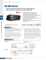
Appearance
Front View
Rear View

DA-682C Series Introduction
1-4
Dimensions
Unit = mm (inch)
Features
The DA-682C computer has the following features:
• IEC 61850-3, IEEE 1613, and IEC 60255 compliant for power substation automation systems
• 7th Generation Intel® Core™ Processor
• Built-in DDR4 memory slot; up to 32 GB capacity
• Two hot-swappable 2.5-inch HDD or SSD storage expansion trays
• Redundant power supply (100 to 240 VAC/VDC)
• EN 50121-4 compliant for railway wayside applications


2
2. Hardware Installation
The DA-682C embedded computers are compact and rugged, making them suitable for industrial applications.
The LED indicators allow users to monitor performance and identify trouble spots quickly, and multiple ports
are provided for connecting a variety of different devices. The DA-682C embedded computers come with a
reliable and stable hardware platform that lets you devote the bulk of your time to application development.
This chapter describes hardware installation and connector interfaces of the DA-682C embedded computers.
The following topics are covered in this chapter:
Installing the Rackmount Ears
Wiring Requirements
Connecting the Power
Wiring the Power Inputs
Grounding the Chassis
Power Wiring Methods
Reset Button
LED
Connecting to Displays
Connecting USB Devices
Installing a USB Dongle Kit
Serial Ports
Gigabit LAN Ports
Digital Inputs/Digital Outputs
Relay Output
Upgrading the Memory Module
Installing an mSATA Storage Card
Installing SATA Hard Disks
Installing the Expansion Module

DA-682C Series Hardware Installation
2-2
Installing the Rackmount Ears
The DA-682C computer comes with two rackmount kits that allow users to mount the computer on to a rack.
Each rackmount kit includes the following items: a rackmount ear and four screws.
Follow these steps to install the rackmount ears.
1. Attach a rackmount ear on the left side of the
DA-682C computer, and fasten four screws
tightly.
2. Attach the other rackmount ear on the right
side of the computer.

DA-682C Series Hardware Installation
2-3
Wiring Requirements
The following common safety precautions should be observed before installing any electronic device:
• Power wires and communication/signal wires should be routed through separate paths. If power and
communication/signal wires must cross paths, make sure the wires are perpendicular at the intersection
point.
• Use the type of signal transmitted through a wire to determine which wires should be bundled together and
which kept separate. The rule of thumb is that wiring that carries similar electrical signals can be bundled
together.
• When necessary, we strongly advise labeling the wiring for all devices in the system.
ATTENTION
Do not run signal or communication wiring and power wiring in the same wire conduit. To avoid interference,
wires with different signal characteristics should b
e routed separately.
ATTENTION
Safety First!
Be sure to disconnect the power cord before installing and/or wiring
your device.
Electrical Current Caution!
Calculate the maximum possible current in each power wire and comm
on wire. Observe all electrical codes
dictating the maximum current allowable for each wire size.
If the current goes above the maximum rating, the wiring could overheat, causing serious damage to your
equipment.
Temperature Caution!
Be
careful when handling the unit. When the unit is
plugged in, the internal components generate heat, and
consequently the
outer casing may feel hot to the touch.
Restricted Access Location
This equipment is intended to be used in Restrict Access Location, like computer room. The access can only be
gained by SERVICE PERSONS or by USERS who have been instructed about the metal chassis of the equipment
is so hot that service persons have to pay special attention or take special protection before
touching it.
Further, the access is through the use of key or security identity system. Only authorized by well trained
professional person can access the restrict access location.
External metal parts are hot!! Before touching it, special attention or protection is necessary.

DA-682C Series Hardware Installation
2-4
Connecting the Power
The DA-682C provides dual power inputs using a terminal block, which is located on the rear panel. Connect the
power cord wires to the screws, and then tighten the screws. The Power LED will light up to indicate that power
is being supplied to the DA-682C, after which the BIOS will initialize the flash disk module, causing the Storage
LED to blink. It should take about 30 to 60 seconds for the operating system to complete the boot up process.
Wiring the Power Inputs
The DA-682C computers come with single power input and dual power inputs models. Refer to the following
diagrams and table for a detailed description of the power input wiring. The terminal numbers referred to in the
table are shown in the diagrams below.
Terminal Number Description Note
1
Power Line
PWR Line is connected to the Line (L) terminal for the AC
power source.
Power Positive
PWR Positive is connect to the Positive (+)
terminal for the
DC power source
2 NA No function
3
Power Neutral
PWR Neutral is connected to the Neutral (N) terminal for the
AC power source.
Power Negative
PWR Negative is connect to the Negative (–) terminal for the
DC Power
4 NA No function
5 Bond Earth
Bond Earth is connected to the Chassis Ground via a
jumper
on the terminal block.

DA-682C Series Hardware Installation
2-5
Grounding the Chassis
There is a grounding connector located on the rear panel of the computer.
Connect the connector to the chassis ground source.
ATTENTION
If protective earthing is use
d as a safeguard, the instructions shall require connection of the equipment
protective earthing conductor to the installation protective earthing conductor (for example, by means of a
power cord connected to a socket
-outlet with earthing connection).
Power Wiring Methods
The DA-682C comes with single or dual power inputs; both AC and DC power sources are supported. Refer to
the following diagrams for detailed wiring methods.
ATTENTION
Equipment must be installed acc
ording to the applicable country’s wiring codes.

DA-682C Series Hardware Installation
2-6
In addition, there is a power button on the rear panel, which allows users to power on the computer in case the
computer is in the sleep or hibernate mode.
Reset Button
Pressing the Reset button initiates a hardware warm reboot. The button plays the same role as a desktop PC’s
reset button. After pressing the reset button, the system will reboot automatically. During normal use, you
should NOT use the Reset Button. You should only use this button if the software is not working properly. To
protect the integrity of data being transmitted or processed, you should always reset the system from the
operating system using the software reboot function.
LED
There are 60 LED indicators on the front panel.

DA-682C Series Hardware Installation
2-7
Information about each LED indicator is given in the following table.
LED Color Description
Power Green Power is on
Off No power input
Storage Yellow/Blinking Data is being written to or read from the storage unit
Off Storage unit is idle
Power 1 Failure Off The 1
st
power supply is on
Red
Error in the 1
st
power supply
Power 2 Failure Off The 2
nd
power supply is on
Red Error in the 2
nd
power supply
Gigabit LAN LEDs 1 to 6
Green
100 Mbps Ethernet mode
Orange 1000 Mbps (Gigabit) Ethernet mode
Serial Port P1/P2 (TX/RX) Green Tx: Serial data is being transmitted
Yellow Rx: Serial data is being received
Programmable LEDs 1 to 8 Green/
Blinking
Can be used to indicate statuses or for debugging, as
defined by users.
Module LEDs 1 to 8
(Module A/Module B)
Green/Orange/
Blinking
Reserved for LAN-port and serial-port expansion cards.
Connecting to Displays
The DA-682C comes with 2 HDMI interfaces on the rear panel, allowing users to connect two displays.
NOTE
I
n order to have a highly reliable video streaming capability, choose certified HDMI cables.

DA-682C Series Hardware Installation
2-8
Connecting USB Devices
The DA-682C comes with 2 USB 2.0 ports on the front panel and 3 USB 3.0 ports on the rear panel. The USB
ports can be used to connect to other peripherals, such as flash drives for expanding the system’s storage
capacity. In addition, both USB ports support system boot up, which can be activated by modifying the BIOS
settings. See Chapter 3: BIOS Setup for details.
Installing a USB Dongle Kit
You can use a USB Dongle Kit to secure your USB dongle inside your DA-682C computer.
NOTE
The USB Dongle Kit is an optional accessory that can be purchased separately.
To install a USB Dongle Kit inside your DA-682C computer, do the following:
1. Power off the DA-682C computer and remove the upper cover of the computer. Find the location of the USB
socket.

DA-682C Series Hardware Installation
2-9
2. The USB Dongle Kit includes a USB plate and a screw.
3. Attach the USB device to the USB port inside the
DA-682C computer.
4. Place the USB plate on the rail, and push down to
the USB device as close as possible. Finally,
fasten the screw on the plate.
5. Replace the upper cover of the computer.
Serial Ports
The DA-682C comes with 2 software-selectable RS-232/422/485 serial ports on the rear panel.

DA-682C Series Hardware Installation
2-10
The ports use terminal blocks. Refer to the following table for the pin assignments:
Pin RS-232 RS-422 RS-485
(4-wire)
RS-485
(2-wire)
1 TxD TxD(+) TxD(+) –
2 RxD TxD(-) TxD(-) –
3
RTS
RxD(+)
RxD(+)
Data(+)
4 CTS RxD(-) RxD(-) Data(-)
5 GND GND GND GND
Gigabit LAN Ports
The DA-682C has 6 Gigabit LAN ports. When a LAN cable is properly connected, the LEDs on the front panel will
glow to indicate a proper connection.
Refer to the following figure and table for the pin sequence and definitions.
Pin 100 Mbps 1000 Mbps
1 Tx+ TRD(0)+
2 Tx- TRD(0)-
3 Rx+ TRD(1)+
4
–
TRD(2)+
5 – TRD(2)-
6 Rx- TRD(1)-
7
–
TRD(3)+
8 – TRD(3)-

DA-682C Series Hardware Installation
2-11
Digital Inputs/Digital Outputs
The DA-682C comes with six digital inputs and two digital outputs in a terminal block. Refer to the following
figure for the location of the DI/DO connectors.
For pin definitions and wiring methods, see the figures below.
Relay Output
The DA-682C provides a relay output located on the rear panel of the computer.
Refer to the figure on the right for detailed pin definition of
the relay output connectors.
Page is loading ...
Page is loading ...
Page is loading ...
Page is loading ...
Page is loading ...
Page is loading ...
Page is loading ...
Page is loading ...
Page is loading ...
Page is loading ...
Page is loading ...
Page is loading ...
Page is loading ...
Page is loading ...
Page is loading ...
Page is loading ...
Page is loading ...
Page is loading ...
Page is loading ...
Page is loading ...
Page is loading ...
Page is loading ...
Page is loading ...
Page is loading ...
Page is loading ...
Page is loading ...
Page is loading ...
Page is loading ...
Page is loading ...
Page is loading ...
Page is loading ...
Page is loading ...
Page is loading ...
-
 1
1
-
 2
2
-
 3
3
-
 4
4
-
 5
5
-
 6
6
-
 7
7
-
 8
8
-
 9
9
-
 10
10
-
 11
11
-
 12
12
-
 13
13
-
 14
14
-
 15
15
-
 16
16
-
 17
17
-
 18
18
-
 19
19
-
 20
20
-
 21
21
-
 22
22
-
 23
23
-
 24
24
-
 25
25
-
 26
26
-
 27
27
-
 28
28
-
 29
29
-
 30
30
-
 31
31
-
 32
32
-
 33
33
-
 34
34
-
 35
35
-
 36
36
-
 37
37
-
 38
38
-
 39
39
-
 40
40
-
 41
41
-
 42
42
-
 43
43
-
 44
44
-
 45
45
-
 46
46
-
 47
47
-
 48
48
-
 49
49
-
 50
50
-
 51
51
-
 52
52
-
 53
53


Moxa DA-682C Series User manual
- Type
- User manual
- This manual is also suitable for
Ask a question and I''ll find the answer in the document
Finding information in a document is now easier with AI
Related papers
-
Moxa DA-682C Series Quick setup guide
-
 Moxa Technologies DA-682C Series Quick Install Guide
-
Moxa V2403C Series User manual
-
Moxa MC-1200 Series User manual
-
-
-
Moxa Technologies UC-8210 Series Quick Install Guide
-
Moxa UC-2100-W Series User manual
-
Moxa Technologies MC-7400 Series User manual
-

Other documents
-
Sharkoon 4044951008049 Datasheet
-
 Land Pride BH1575 User manual
-
 Moxa Technologies DA-685 Series User manual
-
 Moxa Technologies DA-682 User manual
-
Hafler Trans-nova TRM8 User manual
-
-
 Land Pride FM20 User manual
-
Apricorn mSATA Wire Quick start guide
-
Belkin F1U119 User manual
-
Hitachi G 23SCY Technical Data And Service Manual


