Page is loading ...

PROFESSIONAL DIGITAL TWO-WAY RADIO
MOTOTRBO
TM
SYSTEM PLANNER


i
Section 1 Introduction
1.1 Welcome to MOTOTRBO
TM
! ................................................................................ 1
1.2 Software Version .................................................................................................. 2
Section 2 System Feature Overview
2.1 MOTOTRBO Digital Radio Technology................................................................ 3
2.1.1 Digital Radio Technology Overview ............................................................ 3
2.1.1.1 Part One: The Analog to Digital Conversion...................................... 3
2.1.1.2 Part Two: The Vocoder and Forward Error Correction (FEC) ........... 3
2.1.1.3 Part Three: Framing........................................................................... 4
2.1.1.4 Part Four: TDMA Transmission ......................................................... 4
2.1.1.5 Standards Compliance ...................................................................... 4
2.1.2 Spectrum Efficiency via Two-Slot TDMA .................................................... 5
2.1.2.1 Frequencies, Channels, and Requirements for
Spectrum Efficiency ............................................................................... 5
2.1.2.2 Delivering Increased Capacity in Existing 12.5 kHz Channels .......... 5
2.1.2.3 Two-Slot TDMA Reduces Infrastructure Equipment.......................... 7
2.1.2.4 Two-Slot TDMA Enables System Flexibility....................................... 8
2.1.2.5 Two-Slot TDMA System Planning Considerations ............................ 9
2.1.3 Digital Audio Quality and Coverage Performance....................................... 9
2.1.3.1 Digital Audio Coverage .................................................................... 10
2.1.3.2 Predicting Digital Audio Coverage ................................................... 11
2.1.3.3 User Expectations for Digital Audio Performance............................ 12
2.1.3.4 Audio Balancing............................................................................... 13
2.2 Basic System Topologies for Digital and Analog Operations ............................. 14
2.2.1 Repeater and Direct Mode Configurations................................................ 14
2.2.1.1 Analog Repeater Mode.................................................................... 15
2.2.1.2 Digital Repeater Mode .....................................................................
15
2.2.1.3 Dynamic Mixed Mode ...................................................................... 15
2.2.1.4 IP Site Connect Mode...................................................................... 16
2.2.1.5 Capacity Plus Mode......................................................................... 18
2.2.1.6 Linked Capacity Plus Mode ............................................................. 20
2.2.2 MOTOTRBO Supports Analog and Digital Operation ............................... 21
2.2.3 MOTOTRBO Channel Access .................................................................. 22
2.2.3.1 Impolite Operation (Admit Criteria of “Always”) ............................... 23
2.2.3.2 Polite to All Operation (Admit Criteria of “Channel Free”)................ 23
2.2.3.3 Polite to Own Digital System Operation (Admit Criteria of
“Color Code Free”) ............................................................................... 24
2.2.3.4 Polite to Other Analog System Operation (Admit Criteria of
“Correct PL”) ........................................................................................ 24

ii
2.2.3.5 Polite or Impolite, or Voice Interrupt While Participating
in a Call (In Call Criteria) ...................................................................... 24
2.2.3.6 Repeater Wake-up Provisioning ...................................................... 25
2.3 MOTOTRBO Digital Features ............................................................................ 26
2.3.1 Digital Voice Features ............................................................................... 26
2.3.1.1 Group Calls...................................................................................... 26
2.3.1.2 Private Calls..................................................................................... 27
2.3.1.3 All Call.............................................................................................. 28
2.3.1.4 DTMF Hot Keypad ........................................................................... 28
2.3.2 Transmit Interrupt...................................................................................... 29
2.3.2.1 Upgrading a System to be Transmit Interrupt Capable ................... 31
2.3.3 Digital Signaling Features ......................................................................... 31
2.3.3.1 PTT ID and Aliasing......................................................................... 32
2.3.3.2 Radio Enable/Disable ...................................................................... 32
2.3.3.3 Remote Monitor ............................................................................... 33
2.3.3.4 Radio Check .................................................................................... 34
2.3.3.5 Call Alert .......................................................................................... 34
2.3.3.6 Remote Voice Dekey ....................................................................... 34
2.3.4 Digital Emergency..................................................................................... 35
2.3.4.1 Emergency Alarm Only.................................................................... 39
2.3.4.2 Emergency Alarm and Call .............................................................. 40
2.3.4.3 Emergency Alarm with Voice to Follow ........................................... 41
2.3.4.4 Emergency Voice Interrupt for Emergency Alarm ........................... 42
2.3.4.5 Emergency Voice Interrupt for Emergency Voice............................ 43
2.3.5 Restricted Access to System (RAS).......................................................... 44
2.3.5.1 Restricted Access to System (RAS) Key Authentication ................. 44
2.3.5.2 Radio ID Range Check .................................................................... 44
2.4 MOTOTRBO Integrated Data............................................................................. 45
2.4.1 Overview ................................................................................................... 45
2.4.2 Text Messaging Services .......................................................................... 46
2.4.2.1 Built-In Text Messaging Service ...................................................... 47
2.4.2.2 Services Provided to a Third-Party Text Message Application........ 48
2.4.2.3 Predictive Text Entry........................................................................ 48
2.4.3 Location Services ..................................................................................... 50
2.4.3.1 Performance Specifications ............................................................. 51
2.4.3.2 Services Provided to a Radio User.................................................. 52
2.4.3.3 Services Provided to a Location Application.................................... 52
2.4.3.4 Services Provided by the MOTOTRBO Location
Services Application.............................................................................
53
2.4.3.5 GPS Revert Channel ....................................................................... 54
2.4.3.6 Enhanced GPS Revert Channel ...................................................... 55

iii
2.4.3.7 Data Revert Channel ....................................................................... 62
2.4.4 Telemetry Services ................................................................................... 63
2.4.4.1 Physical Connection Information ..................................................... 64
2.4.4.2 Telemetry Examples ........................................................................ 64
2.4.5 Data Precedence and Data Over Voice Interrupt...................................... 65
2.5 Scan ................................................................................................................... 66
2.5.1 Priority Sampling ....................................................................................... 67
2.5.2 Channel Marking....................................................................................... 68
2.5.3 Scan Considerations ................................................................................. 69
2.5.3.1 Scanning and Preamble .................................................................. 70
2.5.3.2 Channel Scan and Last Landed Channel ........................................ 71
2.5.3.3 Scan Members with Similar Receive Parameters............................ 72
2.5.4 Transmit Interrupt and Scan...................................................................... 74
2.6 Site Roaming...................................................................................................... 75
2.6.1 Passive Site Searching ............................................................................. 76
2.6.2 Active Site Searching................................................................................ 78
2.6.3 Roaming Considerations........................................................................... 80
2.6.3.1 Configuring a Roam List .................................................................. 80
2.6.3.2 Scan or Roam.................................................................................. 82
2.6.3.3 Configuring the Roaming RSSI Threshold....................................... 82
2.6.3.4 Setting Beacon Duration and Beacon Interval................................. 87
2.6.3.5 Emergency Revert, GPS/Data Revert, and
Roaming Interactions ........................................................................... 89
2.6.3.6 Performance while Roaming............................................................ 91
2.6.3.7 ARS Registration on Roaming......................................................... 92
2.7 Voice and Data Privacy ...................................................................................... 92
2.7.1 Types of Privacy........................................................................................ 92
2.7.2 Strength of the Protection Mechanism ...................................................... 93
2.7.3 Scope of Protection................................................................................... 93
2.7.4 Effects on Performance............................................................................. 94
2.7.5 User Control Over Privacy ........................................................................ 94
2.7.6 Privacy Indications to User........................................................................ 96
2.7.7 Key Mismatch............................................................................................ 97
2.7.8 Keys and Key Management ...................................................................... 97
2.7.9 Multiple Keys in a Basic Privacy System .................................................. 98
2.7.10 Data Gateway Privacy Settings............................................................... 99
2.7.11 Protecting One Group’s Message from Another ................................... 100
2.7.12 Updating from Basic Privacy to Enhanced Privacy ............................... 100
2.8 Repeater Diagnostics and Control (RDAC)...................................................... 101
2.8.1 Connecting Remotely via the Network .................................................... 103

iv
2.8.2 Connecting Locally via the USB.............................................................. 104
2.8.3 Connecting Locally via GPIO Lines......................................................... 105
2.8.3.1 RDAC Local Settings Rear Accessory Port
CPS Programmable Pins ................................................................... 106
2.8.4 Redundant Repeater Setup .................................................................... 107
2.8.5 Dual Control Considerations ................................................................... 108
2.8.6 General Considerations When Utilizing the RDAC Application to
Set Up the Network Connection ...................................................................... 109
2.9 IP Repeater Programming (IRP) ...................................................................... 110
2.9.1 System Configuration for IRP Support.................................................... 110
2.10 Over-the-Air Radio Programming (OTAP)...................................................... 112
2.10.1 Basic Deployments of OTAP Software ................................................. 113
2.10.1.1 Local Single Channel Configuration ............................................ 113
2.10.1.2 Local Single Channel Configuration with
Presence Notifier (PN) ....................................................................... 114
2.10.1.3 Remote Client Configuration........................................................ 115
2.10.1.4 Remote Client Configuration with Multiple CPS Servers ............. 115
2.10.1.5 Remote Device Programmer Configuration................................. 116
2.10.1.6 Multi-Channel Configuration ........................................................ 117
2.10.2 Process Flow for Over-the-Air Programming ........................................ 117
2.10.2.1 Initial Programming of the Essential Communication
Parameters into the Radio via Wired CPS ......................................... 118
2.10.2.2 Populating the CPS Server with Current
Radio Configurations.......................................................................... 119
2.10.2.3 Modifying the Radio Configurations within the CPS Server......... 121
2.10.2.4 Delivering the Modified Radio Configurations to the Radios ....... 121
2.10.2.5 Applying (or Switching Over) the Delivered
Radio Configurations.......................................................................... 122
2.11 Voice Operated Transmission (VOX) ............................................................. 124
2.11.1 Operational Description......................................................................... 124
2.11.2 Usage Consideration............................................................................. 124
2.11.2.1 Suspending VOX ......................................................................... 124
2.11.2.2 Talk Permit Tone ......................................................................... 124
2.11.2.3 Emergency Calls.......................................................................... 125
2.11.2.4 Transmit Interrupt ........................................................................ 125
2.12 Lone Worker................................................................................................... 125
2.13 BluetoothTM Support ..................................................................................... 126
2.13.1 Bluetooth Pairing and Connection......................................................... 126
2.13.1.1 Pairing a Bluetooth Device with Display Radios .......................... 126
2.13.1.2 Pairing a Bluetooth Device with Non-Display Radios .................. 126
2.13.2 Bluetooth Headset/PTT and Radio Operation....................................... 127

v
2.13.2.1 Radio Operation with COTS Headset.......................................... 127
2.13.2.2 Radio Operation with Motorola Headset/PTT .............................. 127
2.13.2.3 Radio Operation with Motorola PTT Only Device (POD)............. 127
2.13.3 Bluetooth Barcode Scanner Operation ................................................. 128
2.13.4 Bluetooth Personal Area Networking (PAN) Operation......................... 128
2.13.5 Recommended Bluetooth Devices........................................................ 129
2.13.6 Avoiding Accidental Connection............................................................ 129
2.14 One Touch Home Revert Button .................................................................... 130
2.15 Password and Lock Feature (Radio Authentication) ...................................... 130
2.16 Digital Telephone Patch (DTP)....................................................................... 131
2.16.1 Phone Call Initiation .............................................................................. 131
2.16.1.1 Call Initiation by a Radio User ..................................................... 132
2.16.1.2 Call Initiation by a Phone User .................................................... 132
2.16.2 During a Phone Call .............................................................................. 133
2.16.3 Ending a Phone Call ............................................................................. 134
2.16.4 Digital Telephone Patch System Configuration..................................... 135
2.16.4.1 Phone Patch in Single Site and IP Site Connect
Local Area Channels (LAC) ............................................................... 135
2.16.4.2 Phone Patch in IP Site Connect Wide Area Channels (WAC)..... 137
2.16.4.3 Phone Patch in Capacity Plus ..................................................... 139
2.17 Analog Features ............................................................................................. 139
2.17.1 Analog Voice Features.......................................................................... 140
2.17.2 MDC Analog Signaling Features........................................................... 140
2.17.3 Quik-Call II Signaling Features ............................................................. 141
2.17.4 Analog Scan Features .......................................................................... 142
2.17.5 Analog Repeater Interface .................................................................... 142
2.17.5.1 Analog Repeater Interface Settings............................................. 142
2.17.5.2 Configuration Summary Table ..................................................... 147
2.17.5.3 Configuration Considerations ...................................................... 148
2.17.6 Auto-Range Transponder System (ARTS)............................................ 151
2.17.7 TX Inhibit Quick Key Override............................................................... 152
2.17.8 Alert Tone Fixed Volume....................................................................... 152
2.17.9 Alert Tone Auto Reset........................................................................... 153
2.17.10 Emergency Permanent Sticky Revert ................................................. 153
2.17.11 Comparison Chart............................................................................... 153
2.18 Third Party Application Partner Program........................................................ 156
2.18.1 MOTOTRBO, the Dealer, and the Accredited
Third-Party Developer...................................................................................... 156
2.18.2 MOTOTRBO Applications Interfaces .................................................... 156
2.18.2.1 ADP Interface with IP Site Connect ............................................. 158
2.18.2.2 ADP Interface with Capacity Plus ................................................ 159

vi
2.18.2.3 ADP Interface with IP Site Connect and Capacity Plus ............... 160
2.18.3 MOTOTRBO Documents Available via the Third Party
Application Partner Program............................................................................ 161
2.18.4 Available Levels of Partnership............................................................. 162
Section 3 System Components and Topologies
3.1 System Components ........................................................................................ 165
3.1.1 Fixed End Components........................................................................... 165
3.1.1.1 Repeater ........................................................................................ 165
3.1.1.2 MTR3000 Base Station/Repeater.................................................. 167
3.1.1.3 MTR3000 Satellite Receiver .......................................................... 170
3.1.1.4 Radio Control Station..................................................................... 172
3.1.1.5 MC1000, MC2000, MC2500 Console............................................ 172
3.1.2 Mobile Components ................................................................................ 173
3.1.2.1 MOTOTRBO Portable.................................................................... 174
3.1.2.2 MOTOTRBO Mobile ...................................................................... 179
3.1.3 Data Applications .................................................................................... 184
3.2 /dual capacity direct mode System Topologies ................................................ 184
3.2.1 Direct Mode/Dual Capacity Direct Mode (DCDM)................................... 184
3.2.1.1 Digital MOTOTRBO Radios in Direct Mode/Dual
Capacity Direct Mode......................................................................... 185
3.2.1.2 Interoperability between Analog MOTOTRBO Radios and
Analog Radios in Direct Mode............................................................ 196
3.2.1.3 Interoperability between Digital MOTOTRBO Radios, Mixed
Mode MOTOTRBO Radios, and Analog Radios in Direct Mode........ 197
3.2.1.4 Direct Mode Spectrum Efficiency................................................... 197
3.2.2 Dual Capacity Direct Mode ..................................................................... 198
3.2.2.1 General Information .......................................................................
198
3.2.2.2 Timeslot Synchronization............................................................... 198
3.2.2.3 Channel Timing Leader (CTL) Preference..................................... 198
3.2.2.4 Color Code..................................................................................... 199
3.2.2.5 Channel Access Rule .................................................................... 199
3.2.2.6 Scan............................................................................................... 199
3.2.2.7 Interoperability and Backward Compatibility.................................. 199
3.2.2.8 Revert Features ............................................................................. 200
3.2.3 Repeater Mode ....................................................................................... 200
3.2.3.1 Digital MOTOTRBO Radios in Repeater Mode ............................. 201
3.2.3.2 Analog MOTOTRBO Radios in Repeater Mode ............................ 217
3.2.4 IP Site Connect Mode ............................................................................. 218
3.2.4.1 Topologies of IP Site Connect System .......................................... 219
3.2.5 Capacity Plus Mode ................................................................................ 229

vii
3.2.5.1 Topologies of Capacity Plus System ............................................. 229
3.2.6 Linked Capacity Plus (LCP) Mode .......................................................... 235
3.2.6.1 Topologies of Linked Capacity Plus System.................................. 236
Section 4 System Design Considerations
4.1 Purpose ............................................................................................................ 241
4.2 Analog to Digital Migration Plans ..................................................................... 241
4.2.1 Pre-Deployment System Integration ....................................................... 241
4.2.2 Analog to Digital Preparation and Migration............................................ 242
4.2.3 New/Full System Replacement ............................................................... 243
4.3 Frequency Licensing ........................................................................................ 244
4.3.1 Acquiring New Frequencies (Region Specific)........................................ 244
4.3.2 Converting Existing 12.5/25 kHz Licenses.............................................. 245
4.3.3 Repeater Continuous Wave Identification (CWID).................................. 245
4.4 Digital Repeater Loading.................................................................................. 246
4.4.1 Assumptions and Precautions................................................................. 246
4.4.2 Voice and Data Traffic Profile ................................................................. 247
4.4.3 Estimating Loading (Single Repeater and IP Site Connect) ................... 248
4.4.4 Estimating Loading (For Capacity Plus).................................................. 249
4.4.5 Estimating Loading (For Linked Capacity Plus) ...................................... 252
4.4.6 Loading Optimization (For Single Repeater and IP Site Connect).......... 253
4.4.6.1 Distribution of High Usage Users................................................... 253
4.4.6.2 Minimize Location Periodic Update Rate....................................... 254
4.4.6.3 Data Application Retry Attempts and Intervals .............................. 256
4.4.6.4 Optimize Data Application Outbound Message Rate .................... 256
4.4.6.5 GPS Revert and Loading............................................................... 257
4.4.6.6 Enhanced GPS Revert – Loading & Reliability.............................. 260
4.4.7 Loading Optimization (For Capacity Plus and Linked Capacity Plus) ..... 264
4.4.7.1 Preference for Using a Frequency................................................. 264
4.4.7.2 Improving Channel Capacity by Adjusting Hang Times................. 264
4.4.7.3 Call Priority .................................................................................... 265
4.4.7.4 Call Initiation .................................................................................. 265
4.5 Multiple Digital Repeaters in Standalone Mode ............................................... 266
4.5.1 Overlapping Coverage Area.................................................................... 266
4.5.2 Color Codes in a Digital System ............................................................. 267
4.5.3 Additional Considerations for Color Codes ............................................. 268
4.6 Multiple Digital Repeaters in IP Site Connect Mode......................................... 269
4.6.1 System Capacity ..................................................................................... 269
4.6.2 Frequencies and Color Code Considerations ......................................... 269
4.6.3 Considerations for the Backend Network................................................ 270

viii
4.6.3.1 Automatic Reconfiguration............................................................. 271
4.6.3.2 Characteristics of Backend Network.............................................. 272
4.6.4 Flow of Voice/Data/Control Messages.................................................... 279
4.6.5 Security Considerations .......................................................................... 280
4.6.6 General Considerations When Setting Up the Network Connection
for an IP Site Connect System......................................................................... 281
4.6.7 Considerations for Shared Use of a Channel.......................................... 282
4.6.8 Migration from Single Site Systems ........................................................ 284
4.6.9 Migration from an Older IP Site Connect System ................................... 284
4.7 Multiple Digital Repeaters in Capacity Plus...................................................... 285
4.7.1 System Capacity ..................................................................................... 285
4.7.2 Frequencies and Color Code Considerations ......................................... 285
4.7.3 Considerations for the Backend Network................................................ 286
4.7.4 Behaviors in Presence of Failures .......................................................... 286
4.7.5 Limiting Interference to Other Systems................................................... 287
4.7.6 Plan for Talkaround Mode....................................................................... 287
4.7.7 Ways to Improve Battery Life .................................................................. 288
4.7.8 Considerations for Configuring Combined Firmware Versions ............... 288
4.8 Multiple Digital Repeaters in Linked Capacity Plus .......................................... 289
4.8.1 System Capacity ..................................................................................... 289
4.8.2 Considerations for Frequencies, Color Code, and Interference.............. 289
4.8.3 Considerations for the Backend Network................................................ 291
4.8.3.1 Backend Network Characteristics.................................................. 292
4.8.3.2 Backend Network Bandwidth Considerations................................ 292
4.8.4 Behaviors in Presence of Failures .......................................................... 294
4.8.4.1 Failure of the Master...................................................................... 295
4.8.4.2 Failure of a Site.............................................................................. 295
4.8.4.3 Failure of a Repeater ..................................................................... 295
4.8.4.4 Failure of the LAN Switch .............................................................. 295
4.8.4.5 Failure of the Backend Network or Router..................................... 296
4.8.4.6 Failure of a Revert Repeater ......................................................... 296
4.8.5 Automatic Reconfiguration ...................................................................... 296
4.8.6 Security Considerations .......................................................................... 296
4.8.7 Migration ................................................................................................. 297
4.8.7.1 Migrating from IP Site Connect...................................................... 298
4.8.7.2 Migration from Capacity Plus......................................................... 298
4.9 Digital Telephone Patch (DTP)......................................................................... 299
4.9.1 Enable/Disable Phone Gateway Repeater for Phone Calls.................... 299
4.9.2 Enable/Disable a Radio from Initiating/Receiving Phone Calls............... 300
4.9.3 Phone Channel Configuration ................................................................. 300

ix
4.9.3.1 One APP Box per Repeater via 4-wire Interface ........................... 300
4.9.3.2 Single Site...................................................................................... 300
4.9.3.3 IP Site Connect.............................................................................. 302
4.9.3.4 Capacity Plus................................................................................. 302
4.9.3.5 Linked Capacity Plus ..................................................................... 302
4.9.4 APP Box Configuration ........................................................................... 302
4.9.5 Phone System Configuration .................................................................. 303
4.9.5.1 Configuring a Radio in a Phone System........................................ 304
4.9.5.2 Configuring a Repeater in a Phone System .................................. 304
4.9.6 Access/De-access Code Configuration................................................... 304
4.9.6.1 Repeater Configuration.................................................................. 305
4.9.6.2 Radio Configuration ....................................................................... 305
4.9.7 Dual Tone Multi Frequency (DTMF) Configuration ................................. 306
4.9.8 Ringing Modes ........................................................................................ 306
4.9.9 Enable/Disable Manual Dial .................................................................... 307
4.9.10 Connecting APP Boxes to the Repeater in Capacity Plus and
Linked Capacity Plus ....................................................................................... 307
4.9.11 PBX Routing Configuration in Capacity Plus ........................................ 308
4.10 Transmit Interrupt System Design Considerations......................................... 309
4.10.1 Interruptible Radios ............................................................................... 309
4.10.2 Voice Interrupt....................................................................................... 309
4.10.3 Emergency Voice Interrupt.................................................................... 310
4.10.4 Data Over Voice Interrupt ..................................................................... 311
4.10.5 Remote Voice Dekey ............................................................................ 312
4.11 Restricted Access to System (RAS) Design Considerations.......................... 313
4.11.1 RAS Key Authentication........................................................................ 313
4.11.2 Radio ID Range Check ......................................................................... 315
4.12 Data Sub-System Design Considerations ...................................................... 316
4.12.1 Computer and IP Network Configurations............................................. 316
4.12.1.1 Radio to Mobile Client Network Connectivity............................... 316
4.12.1.2 Radio to Air Interface Network Connectivity ................................ 317
4.12.1.3 Application Server Control Station Network Connectivity ............ 320
4.12.1.4 Control Station Considerations .................................................... 321
4.12.1.5 Multi-Channel Device Driver (MCDD) and Required
Static Routes...................................................................................... 323
4.12.1.6 Application Server and Dispatcher Network Connectivity............ 323
4.12.1.7 MOTOTRBO Subject Line Usage................................................ 324
4.12.1.8 MOTOTRBO Example System IP Plan ....................................... 324
4.12.1.9 Application Server Network Connection Considerations ............. 326
4.12.1.10 Reduction in Data Messages (When Radios Power On)........... 326
4.12.1.11 Optimizing for Data Reliability.................................................... 327

x
4.12.1.12 Optimizing for Data Throughput................................................. 329
4.12.1.13 Data Revert Channels for Capacity Plus and
Linked Capacity Plus.......................................................................... 331
4.12.2 Mobile Terminal and Application Server Power Management
Considerations................................................................................................. 334
4.13 Customer Fleetmap Development.................................................................. 335
4.13.1 Identifying a Functional Fleetmap Design Team................................... 335
4.13.2 Identifying Radio Users......................................................................... 336
4.13.3 Organizing Radio Users into Groups .................................................... 337
4.13.3.1 Configuration of Groups............................................................... 338
4.13.4 Assigning IDs and Aliases..................................................................... 338
4.13.4.1 Identifying Radio IDs.................................................................... 339
4.13.4.2 Assigning Radio Aliases .............................................................. 339
4.13.4.3 Identifying Group IDs ................................................................... 340
4.13.4.4 Assigning Group Aliases.............................................................. 340
4.13.5 Determining Which Channel Operates in Repeater Mode or
Direct Mode/Dual Capacity Direct Mode.......................................................... 341
4.13.6 Determining Feature Assignments........................................................ 341
4.13.6.1 Determining Supervisor Radios ................................................... 341
4.13.6.2 Private Calls................................................................................. 341
4.13.6.3 All Call.......................................................................................... 342
4.13.6.4 Radio Disable .............................................................................. 342
4.13.6.5 Remote Monitor ........................................................................... 343
4.13.6.6 Radio Check ................................................................................ 343
4.13.6.7 Call Alert ...................................................................................... 343
4.13.6.8 RX Only ....................................................................................... 343
4.13.6.9 Remote Voice Dekey ................................................................... 343
4.13.7 Emergency Handling Configuration ...................................................... 344
4.13.7.1 Emergency Handling User Roles................................................. 344
4.13.7.2 Emergency Handling Strategies .................................................. 345
4.13.7.3 Acknowledging Supervisors in Emergency.................................. 347
4.13.7.4 Extended Emergency Call Hang Time......................................... 347
4.13.7.5 Emergency Revert and GPS/Data Revert Considerations .......... 347
4.13.8 Channel Access Configuration.............................................................. 352
4.13.9 Zones and Channel Knob Programming............................................... 353
4.14 Base Station Identifications (BSI) Setting
Considerations ....................................................................................................... 354
4.15 GPS Revert Considerations (For Single Repeater and
IP Site Connect only).............................................................................................. 356
4.16 Enhanced GPS Revert Considerations .......................................................... 357
4.16.1 Single Site Mode................................................................................... 358

xi
4.16.2 Capacity Plus and Linked Capacity Plus Modes................................... 358
4.16.3 IP Site Connect Mode ........................................................................... 358
4.16.3.1 Other Considerations................................................................... 359
4.17 Enhanced Channel Access Consideration ..................................................... 360
4.17.1 Enhanced Channel Access Advantages ............................................... 360
4.17.2 Enhanced Channel Access Limitations................................................. 361
4.18 Failure Preparedness ..................................................................................... 362
4.18.1 Direct Mode Fallback (Talkaround) ....................................................... 362
4.18.2 Uninterrupted Power Supplies (Battery Backup)................................... 362
4.19 Dynamic Mixed Mode System Design Considerations................................... 363
4.19.1 Dynamic Mixed Mode System Configuration Considerations ............... 363
4.19.2 Loading Considerations in a Dynamic Mixed Mode System ................. 365
4.20 Over-the-Air Radio Programming Design Considerations.............................. 366
4.20.1 Advanced Over-the-Air Radio Programming Configurations ................ 366
4.20.1.1 Control Station Configuration....................................................... 366
4.20.1.2 Conventional Configurations........................................................ 367
4.20.1.3 Trunking Configurations............................................................... 371
4.20.1.4 Coexistence with Third Party Data Applications .......................... 378
4.20.2 Over-the-Air Authentication Key Management...................................... 380
4.20.3 Over-the-Air Privacy Key Management................................................. 381
4.20.3.1 Updating the Privacy Keys in the System.................................... 381
4.20.4 Performance of Over-the-Air Programming .......................................... 382
4.20.4.1 Time to Complete Over-the-Air Operations ................................. 382
4.20.4.2 Performance Impact on Other Services....................................... 386
4.20.5 CPS Computer Specifications............................................................... 389
4.21 Configurable Timers ....................................................................................... 390
Section 5 Sales and Service Support Tools
5.1 Purpose ............................................................................................................ 395
5.2 Applications Overview ...................................................................................... 395
5.3 Service Equipment ........................................................................................... 396
5.3.1 Recommended Test Equipment.............................................................. 396
5.4 Documentation and Trainings .......................................................................... 397
5.4.1 MOTOTRBO Documentation .................................................................. 397
Section A Control Station Installation
A.1 Data Bearer Service............................................................................................. 1
A.2 Interference.......................................................................................................... 2
A.3 Control Station Installation Considerations .......................................................... 3

xii
Notes

Introduction 1
68007024085 November 2012
SECTION 1 INTRODUCTION
1.1 Welcome to MOTOTRBO
TM
!
Improving workforce productivity and operational effectiveness requires superior communications
quality, reliability, and functionality. MOTOTRBO is the first digital two-way radio system from
Motorola specifically designed to meet the requirements of professional organizations that need a
customizable, business critical, private communication solution using licensed spectrum.
MOTOTRBO combines the best in two-way radio functionality with digital technology to deliver
increased capacity and spectral efficiency, integrated data applications and enhanced voice
communications.
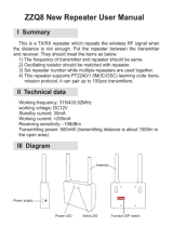
MOTOTRBO is an integrated voice and data system solution comprising of mobile and portable
radios, audio and energy accessories, repeaters, and a third-party application partner program.
This system planner will enable the reader to understand the features and capabilities of the
MOTOTRBO system, and will provide guidance on how to deploy and configure the system and its
components to take advantage of its advanced capabilities.
This system planner is divided into 5 sections, with the first being this introduction. Section 2
provides an overview of system level features. Section 3 describes the system components in
more detail. Section 4 provides guidance on system design considerations including configuration
of components. Section 5 provides product sales and support information.
This system planner is complementary to additional training and documentation including:
• Radio Customer Programming Software (CPS) and related training
• System workshop/system service training
• Product specification sheets
Figure 1-1 MOTOTRBO System

2 Introduction
November 2012 68007024085
1.2 Software Version
All the features described in the System Planner are supported by the following software versions:
•Radios - R02.06.00 and above
• Repeaters - R02.20.00 and above

System Feature Overview 3
68007024085 November 2012
SECTION 2 SYSTEM FEATURE OVERVIEW
2.1 MOTOTRBO Digital Radio Technology
This section provides a brief overview of MOTOTRBO digital radio technology. It addresses two of
the primary benefits delivered by this technology: spectral efficiency and improved audio
performance.
2.1.1 Digital Radio Technology Overview
The digital radio technologies employed by MOTOTRBO can be summarized as follows:
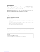
Figure 2-1 “MOTOTRBO Digital Radio Technology” is broken down into four parts which are
described in the following subsections.
2.1.1.1 Part One: The Analog to Digital Conversion
When a radio user presses the Push-To-Talk (PTT) button and begins speaking, his voice is
received by the radio microphone and converted from an acoustic waveform to an analog
electrical waveform. This voice waveform is then sampled by an analog to digital converter. In
typical radio applications, a 16-bit sample is taken every 8 kHz, this produces a 128,000bps (bits
per second) digital bitstream, which contains far too much information to send over a 12.5 kHz or
25 kHz radio channel. Therefore some form of compression is required.
2.1.1.2 Part Two: The Vocoder and Forward Error Correction (FEC)
Vocoding (Voice encoding) compresses speech by breaking it into its most important parts and
encoding them with a small number of bits, while greatly reducing background noise. Vocoding
compresses the voice bitstream to fit the narrow (for MOTOTRBO) 6.25 kHz equivalent radio
channel. The MOTOTRBO vocoder is AMBE+2
TM
which was developed by Digital Voice System,
Inc. (DVSI), a leader in the vocoding industry. This particular vocoder works by dividing speech
into short segments, typically 20 to 30 milliseconds in length. Each segment of speech is analyzed,
and the important parameters such as pitch, level, and frequency response are extracted. These
parameters are then encoded using a small number of digital bits. The AMBE+2
TM
vocoder is the
Figure 2-1 MOTOTRBO Digital Radio Technology
1 2 3 4
data input
or
microphone input
digital
bitstream
compressed
digital voice
digital
packets
Slot 1:
Radio Transmit
Transmission,
Encoding &
RF Amplication
Framing
header payload
Vocoder &
Forward Error
Correction
IP Data Interface
Analog to Digital
Slot 2:
Radio waits;
spectrum available
to another radio
Slot 1:
Radio Transmit
next burst

4 System Feature Overview
November 2012 68007024085
first to demonstrate very low bit rates while producing toll-quality speech such as traditionally
associated with wireline telephone systems.
Together with the vocoding process, Forward Error Correction (FEC) is also applied. FEC is a
mathematical checksum technique that enables the receiver to both validate the integrity of a
received message and determine which, if any, bits have been corrupted. FEC enables the
receiver to correct bit errors that may have occurred due to radio frequency (RF) channel
impairment. This effectively rejects noise that can distort an analog signal and by comparison
enables more consistent audio performance throughout the coverage area. At this stage, the
vocoder has already compressed the 128,000bps input signal to 3,600bps.
2.1.1.3 Part Three: Framing
In framing, the vocoded speech is formatted for transmission. This includes organizing the voice
and any embedded signaling information (such as color code, group ID, PTT ID, call type, etc.)
into packets. These packets form a header and payload type of structure – the header contains the
call control and ID information, and the payload contains the vocoded speech. This same structure
can also relay Internet Protocol (IP) data packets – the IP packets are simply an alternative form of
payload to the MOTOTRBO radio. The header information is repeated periodically throughout the
transmission, thereby improving the reliability of the signaling information as well as enabling a
receiving radio to join a call that may already be in progress – we refer to this condition as “late
entry”.
2.1.1.4 Part Four: TDMA Transmission
Finally, the signal is encoded for a Frequency Modulation (FM) transmission. The bits contained in
the digital packets are encoded as symbols representing the amplitude and phase of the
modulated carrier frequency, amplified, and then transmitted.
TDMA (Time Division Multiple Access) organizes a channel into 2 time slots: a given radio’s
transmitter is active only for short bursts, which provides longer battery life. By transmitting only on
their alternating time slots, two calls can share the same channel at the same time without
interfering with one another, thereby doubling spectrum efficiency. Using TDMA, a radio transmits
only during its time slot (i.e. it transmits a burst of information, then waits, then transmits the next
burst of information).
2.1.1.5 Standards Compliance
The digital protocols employed in MOTOTRBO (from vocoding and forward error correction to
framing, transmission encoding, and transmission via two-slot TDMA) are fully specified by the
ETSI
1
DMR
2
Tier 2
3
Standard, which is an internationally recognized standard with agreements
among its supporting members. Although formal interoperability testing and verification processes
for this standard have yet to fully mature, Motorola anticipates that MOTOTRBO radio systems will
be interoperable with other solutions that comply to the ETSI DMR Tier 2 standard.
1. European Telecommunications Standards Institute
2. Digital Mobile Radio
3. Tier 2 indicates full power conventional operation in licensed channels for professional and commercial
users.

System Feature Overview 5
68007024085 November 2012
2.1.2 Spectrum Efficiency via Two-Slot TDMA
2.1.2.1 Frequencies, Channels, and Requirements for Spectrum Efficiency
A radio communications channel is defined by its carrier frequency, and its bandwidth. The
spectrum of available carrier frequencies is divided into major bands (such as 800/900 MHz, VHF,
and UHF), and the majority of licensed channels in use today have widths of either 25 kHz or 12.5
kHz. As the airwaves have become increasingly crowded, new standards and technologies that
allow more radio users to share the available spectrum in any given area are needed. The demand
for greater spectral efficiency is being driven, in part, by regulatory agencies. In the U.S., for
example, the Federal Communications Commission (FCC) requires manufacturers to offer only
devices that operate within 12.5 kHz VHF and UHF channels by 2011. By the year 2013, all VHF
and UHF users are required to operate in 12.5 kHz channels.
The next logical step is to further improve the effective capacity of 12.5 kHz channels. While there
is no current mandate requiring a move to 6.25 kHz, such discussions are on-going at the FCC
and other agencies. It’s only a matter of time before the ability to carry two voice paths in a single
12.5 kHz channel, also known as 6.25 kHz equivalent efficiency, becomes a requirement in 800/
900 MHz, VHF, and UHF bands. Presently, FCC rules are in place to mandate manufacturers to
build radios capable of the 6.25 kHz efficiency for 800/900 MHz, VHF, and UHF bands, but the
enforcement of these rules are put on hold. In the meantime, MOTOTRBO offers a way to divide a
12.5 kHz channel into two independent time slots, thus achieving 6.25 kHz-equivalent efficiency
today.
2.1.2.2 Delivering Increased Capacity in Existing 12.5 kHz Channels
MOTOTRBO uses a two-slot TDMA architecture. This architecture divides the channel into two
alternating time slots, thereby creating two logical channels on one physical 12.5 kHz channel.
Each voice call utilizes only one of these logical channels, and each user accesses a time slot as if
it is an independent channel. A transmitting radio transmits information only during its selected
slot, and will be idle during the alternate slot. The receiving radio observes the transmissions in
either time slot, and relies on the signaling information included in each time slot to determine
which call it was meant to receive.

6 System Feature Overview
November 2012 68007024085
By comparison, analog radios operate on the concept of Frequency Division Multiple Access
(FDMA). In FDMA, each transmitting radio transmits continuously on a designated channel, and
the receiving radio receives the relevant transmission by tuning to the desired carrier frequency.
TDMA thereby offers a straightforward method for achieving 6.25 kHz equivalency in 12.5 kHz
repeater channels – a major benefit for users of increasingly crowded licensed bands. Instead of
dividing channels into smaller slices of decreased bandwidth – which is what would be required to
increase spectrum efficiency with FDMA methods, TDMA uses the full 12.5 kHz channel
bandwidth, but increases efficiency by dividing it into two alternating time slots. Additionally, this
method preserves the well-known radio frequency (RF) performance characteristics of the 12.5
kHz signal. From the perspective of RF physics – that is, actual transmitted power and radiated
emissions – the 12.5 kHz signal of two-slot TDMA occupies the channel, propagates, and
performs essentially in the same way as today’s 12.5 kHz analog signals. With the added
advantages of digital technology, TDMA-based radios can work within a single repeater channel to
provide roughly twice the traffic capacity, while offering RF coverage performance equivalent to, or
better than, today’s analog radio.
Figure 2-2 Comparison between Today’s Analog and MOTOTRBO
Time
12.5kHz Analog
- 1 voice for each 12.5kHz channel
- A single repeater for each channel
12.5kHz TDMA
- Divides existing channel into two timeslots
- Delivers twice the capacity through repeater
- Performance is same or better than 12.5kHz FDM
A
- Single repeater does work of two repeaters
- Reduces need for combining equipment
- Enables 40% increase in radio battery life
Regulatory
emissions
mask
Slot 1
Slot 1
Slot 1
Slot 2
Slot 2
Slot 2
Frequency
12.5KHz channel
Frequency
12.5KHz channel
Today’s Analog
Today’s Analog
MOTOTRBO
MOTOTRBO
/