Page is loading ...

Instruction
Manual
8205B_002-798e-03.19
Uniaxial
high temperature
accelerometer
Type 8205B...
IECEx
ä

Instruction
Manual
8205B_002-798e-03.19
Uniaxial
high temperature
accelerometer
Type 8205B...
IECEx
ä


Page 1
8205B_002-798e-03.19
Thank you for choosing a Kistler quality product charac-
terized by technical innovation, precision and long life.
Information in this document is subject to change without
notice. Kistler reserves the right to change or improve its
products and make changes in the content without obliga-
tion to notify any person or organization of such changes or
improvements.
© 2017 ... 2019 Kistler Group. Kistler Group products are
protected by various intellectual property rights. For more
details visit www.kistler.com. The Kistler Group includes
Kistler Holding AG and all its subsidiaries in Europe, Asia,
the Americas and Australia.
Kistler Group
Eulachstrasse 22
8408 Winterthur
Switzerland
Tel. +41 52 224 11 11
info@kistler.com
www.kistler.com
Foreword
Foreword

Uniaxial high temperature accelerometer Type 8205B...
8205B_002-798e-03.19_
Page 2
Content
1. Introduction .................................................................................................................................3
2. Important information .................................................................................................................4
2.1 Protection and standards ....................................................................................................4
2.2 Precautions .........................................................................................................................5
2.3 Disposal instructions for electrical and electronic equipment .............................................5
3. Product description ....................................................................................................................6
3.1 Technical data .....................................................................................................................6
3.2 Ordering key .......................................................................................................................6
4. Operation ....................................................................................................................................7
4.1 General instructions for operation ......................................................................................7
4.2 Operation in not potentially explosive area .........................................................................7
4.2.1 Sensor execution...................................................................................................7
4.2.2 Ground Isolated Measuring Chain.........................................................................7
4.2.3 Marking ..................................................................................................................8
4.3 Operation in potentially explosive area ...............................................................................9
4.3.1 Instructions for operation in potentially explosive environments ...........................9
4.3.2 Sensor execution...................................................................................................9
4.3.3 Marking ..................................................................................................................9
4.3.4 Non-incendive equipment (Ex-nA) for operation in zone 2..................................10
4.3.5 Intrinsically safe equipment (Ex-ia) ....................................................................11
5. Installation .................................................................................................................................12
5.1 Mounting template / mounting bore ..................................................................................12
5.2 Sensor mounting and removal ..........................................................................................13
5.2.1 Mounting of the sensor ........................................................................................13
5.2.2 Sensor removal ...................................................................................................14
5.3 Cablehandlingandxation ..............................................................................................14
5.4 Electrical connections .......................................................................................................14
5.5 Electro mechanical connection ........................................................................................15
5.5.1 ConnectiontoKistlerchargeamplierType5181/5183/5185 .........................15
5.5.2 Connection through an obstruction .....................................................................16
5.6 Service and maintenance .................................................................................................18
5.7 Measuring chain compontents and accessories ...............................................................18
6. Calibration and repair ..............................................................................................................19
6.1 Calibration ........................................................................................................................19
6.2 Repair ...............................................................................................................................19
7. EC Decleration of conformity...................................................................................................20
Total pages 20

Introduction
Page 3
8205B_002-798e-03.19
1. Introduction
Please read through this manual thoroughly to enable you
to fully exploit the various features of your product.
To the extent permitted by law Kistler accepts no liability
if this instruction manual is not followed or products other
than those listed under Accessories are used.
These instructions describe the piezoelectric uniaxial high
temperature accelerometer Type 8205B.
Our thermoacoustics product and application brochures,
in addition to our detailed data sheets, will provide
you with an overview of our product range.
If you require additional assistance beyond what can be
located online or in this manual, please contact Kistler‘s
extensive support organization or visit us online at
www.kistler.com/thermoacoustics

Uniaxial high temperature accelerometer Type 8205B...
8205B_002-798e-03.19_
Page 4
2. Important information
It is essential to review the following information, which is
intended to ensure your personal safety when working
with high temperature acceleration sensors and contrib-
ute toward a long-fault-free service life.
To the extent permitted by law Kistler accepts no liability
if this instruction manual is not followed or products other
than those listed under Accessories are used.
2.1 Protection and standards
The instruments are CE-compliant within the meaning of
EU Directive 2004/108/EU and conform to interna-
tional EMC standard EN 61000-6-3 emitted interference
EN61000-6-2 interference immunity EN 61326-1 (class
A and B) compliance is required with the correspond-
ing installation notes. All equipment is tested and has
left the factory in a perfect, safe condition. In order
to maintain this condition and ensure safe operation,
compliance is required with the instructions and warn-
ing notes contained within this manual or imprinted on
the product itself.
Compliance with local safety regulations, which may
apply to the use of power line operated electrical and
electronic equipment, is strongly recommended.
The sensor conforms to EU Standard 2004/108/EU and
meets EMC standards. Additionally the following require-
ments are met:
ISO 9001
Emission EMC
EN 61000-6-3:2007 + A1:2011
EN 61000-6-4:2007 + A1:2011
EN 61326-1:2013 (Class A+B equipment)
Immunity EMC
EN 61000-6-1:2007
EN 61000-6-2:2005
EN 61326-1:2013 (Class A+B equipment)
Environmental Testing
IEC 60068-2-1 Cold
IEC 60068-2-2 Dry heat
IEC 60068-2-6 Vibration (sinusoidal)
IEC 60068-2-14 Change of Temperature
IEC 60068-2-27 Shock

Important information
Page 5
8205B_002-798e-03.19
IEC 60068-2-30 Damp heat, cyclic
IEC 60068-2-32 Free fall
IEC 60529 IP-Protection degree
Explosion Protection
According ATEX Directive 2014/34/EU
Complies with the following normatives:
general regulations
EN 60079-0:2012+A11:2013/IEC 60079-0:2011
intrinsically safe
EN 60079-11:2012/IEC 60079-11:2011
non-indencive
EN 60079-15:2010/IEC 60079-15:2010
2.2 Precautions
Compliance with the following precautionary measures
is vital to ensure safe and reliable operation.
The equipment should be used only under the specified
operating conditions.
If there is evidence that safe operation is no longer pos-
sible, the instrument must be powered off and rendered
safe against accidental start-up.
Safe operation is no longer possible when the product
shows visible signs of damage
is no longer operating
has been subjected to prolonged storage under
unsuitable conditions
2.3 Disposal instructions for electrical and electronic equipment
Do not discard old electronic instruments in municipal trash.
For disposal at end of life, please return this product to an
authorized local electronic waste disposal service or contact
the your local Kistler sales office for disposal instructions.

Uniaxial high temperature accelerometer Type 8205B...
8205B_002-798e-03.19_
Page 6
3. Product description
Basic execution
Sensor type 8205B… is a 2-wire, internally ground isolated
differential piezoelectric accelerometer. The sensor is avail-
able with integrated cable options with different levels of
protection.
Execution for operation in hazardous areas (Ex-Versions)
The sensor is available for operaion in hazardous areas. The
Ex-Version Type 8205BE… can be used in Zones 0, 1 and 2
(Ex-ia) resp. Zone 2 (Ex-nA).
3.1 Technical data
The technical specifications are given in data sheet
No. 003-253
3.2 Ordering key
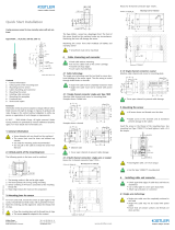
Fig. 1: Ordering key
EX-Certification
no Ex-Certification –
Ex- ia; Ex-nA E
Sensitivity
20 pC/g 1
50 pC/g 2
100 pC/g 3
Cable type
No cable A
Without extra protection B
With steel overbraid C
With spiral metal hose D
With hermetic corrugated metal hose E
Cable termination
Default lead lenghts (40,20) D
Custom lead lenghts C
(x25 ...500, y 0 ...500)
Cable length
Integral cable; 5m 05
Integral cable; 10m 10
Integral cable; 20m 20
Integral cable; customer specified Sp
(0.5m - 30m)
Ordering Key
Type 8205B J

Operation
Page 7
8205B_002-798e-03.19
4. Operation
For proper operation it is necessary to first determine
whether the sensor is installed in a potentially explosive
atmosphere.
4.1 General instructions for operation
The following instructions regarding the installation and
operation must be followed:
The sensor is hermetically sealed. The integral cable
meets ingress protection ≥IP54 and must be protected
against adverse environmental effects where necessary.
The sensor may only be used for its intended purpose.
Any violation will waive all warranties and responsibili-
ties of the manufacturer.
IP degree has to be maintained.
The EU type examination certificate must be observed
as well as any special conditions that may be specified.
4.2 Operation in not potentially explosive area
4.2.1 Sensor execution
In non-hazardous environments the sensor without
Ex-certification Type 8205B- … can be used
4.2.2 Ground Isolated Measuring Chain
Fig. 2: Example of a recommended measuring chain

Uniaxial high temperature accelerometer Type 8205B...
8205B_002-798e-03.19_
Page 8
4.2.3 Marking
The standard execution, “non Ex-Version” is marked as
follows:
Kistler Instrumente AG
Winterthur Switzerland
Sensor Type: 8205B- …
SN: …

Operation
Page 9
8205B_002-798e-03.19
4.3 Operation in potentially explosive area
4.3.1 Instructions for operation in potentially explosive environments
In addition to the instructions for proper operation in Section
4.1 the following instructions must be followed for instal-
lation and operation in potentially explosive environments:
The sensor can be used in intrinsically safe circuits in
zones 0, 1 and 2
The sensor can be used in non sparking circuits in zone 2.
Installation and operation of the equipment in po-
tentially explosive environments must be executed in
accordance to the explosion protection standards of the
respective country.
Installation of intrinsically safe circuits must be conduct-
ed by qualified and authorized personnel only and in
accordance with the instructions of the contractor.
All electrical connections must be properly connected.
No modifications are permitted on any equipment that
is certified for use in potentially explosive environments.
Defective sensors must be returned to the manufacturer.
4.3.2 Sensor execution
For applications in potentially explosive environments the
sensor version Type 8205BE … (certified ‚Ex-nA‘ and
‚Ex-ia‘) must be used.
4.3.3 Marking
The complete ATEX and IECEX marking is shown on the
package:
Marking for type of protection
Kistler Instrumente AG
Winterthur, Schweiz
Type 8205BE
SN …

Uniaxial high temperature accelerometer Type 8205B...
8205B_002-798e-03.19_
Page 10
Type of protection Ex – ia (intrinsically safe) Ex – nA (non sparking)
Marking on product
package
ATEX II 1G Ex ia IIC T6 …270°C Ga
-55°C ≤ Ta ≤ +260°C
BASEEFA09ATEX0234
ATEX II 3G Ex na IIC T6 …270°C Gc
-55°C ≤ Ta ≤ +260°C
BASEEFA17ATEX0017X
IECEx Ex ia IIC T6 …T270°C Ga
IECEx BAS 09.0112
IECEx Ex nA IIC T6 …270°C Gc
IECEx Bas 17.0012X
Specific Conditions
of use
1. Equipment description, for ambient temperature
Ta (–55 … 260°C) installation restrictions.
2. Where the integral cable has flying leads, these
must be provided with a degree of protection of at
least IP20 when installed.
1. Equipment description, for ambient tempera-
ture Ta (–55 … 260°C) installation restrictions.
2.Where the integral cable has flying leads, these
must be provided with a degree of protection of
at least IP20 when installed.
Minimal marking on
sensor
BASEEFA17ATEX0017X
BASEEFA09ATEX0234
IECEx BAS 17.0012X
IECEx BAS 09.01120
Table 1: Marking for type of protection
Minimal marking for 'Ex-nA' and 'Ex-ia'
Due to lack of space the minimal marking is engraved on
the sensor.
4.3.4 Non-incendive equipment (Ex-nA) for operation in zone 2
4.3.4.1 Non sparking measuring chain (Ex - Version)
The sensor can be used in non sparking circuits in zone 2.
For operation in potentially explosive environments the sen-
sor must be operated with an Ex-certified differential charge
amplifier.
Fig. 3: Example of a Non-incentive measuring chain for
zone 2
BASEEFA17ATEX0017X
BASEEFA09ATEX0234
IECEx BAS 17.0012X
IECEx BAS 09.0112

Operation
Page 11
8205B_002-798e-03.19
4.3.5 Intrinsically safe equipment (Ex-ia)
4.3.5.1 Intrinsically safe measuring chain (Ex - version)
The sensor can be used in intrinsically safe circuits in Zones
0, 1 or 2.
For operation in potentially explosive environments the sen-
sor must be operated with an Ex-certified differential charge
amplifier and an appropriate Ex-certified barrier.
The entity parameters between sensor and differential
charge amplifier and the parameters between differential
charge amplifier and barrier must be appropriately matched.
4.3.5.2 Entity Parameter of the Sensor
The entity parameters of the sensor are:
Ui V ≤30
Li mA ≤130
Pi W ≤0,8
Ci nF ≤21 + 0.2nF/m
Li μH ≤30 + 1.5 μH/m
Fig. 4: Example of an Intrinsically safe measuring chain
for Zone 0, 1 or 2

Uniaxial high temperature accelerometer Type 8205B...
8205B_002-798e-03.19_
Page 12
5. Installation
The quality of the threaded holes as well as the installation
according to the instructions are essential to assure a proper
performance of the sensor within the given specification.
5.1 Mounting template / mounting bore
To install the sensor, a smooth and flat surface is mandatory.
The Mounting Template (Type 8443AT1) is a sticker which
helps to determine the correct location of the threaded
(M4x6) hole.
Werkstückkanten nach ISO 13715
-0,2
+0,25
Allgemeintoleranzen
Längenmasse
Abmasse
Winkelmasse kürz. Schenkel
Abmasse
...10
±0°20'
* ...0,5
> 10...50
>0,5...3
>120...400 >400..1000
±0°30'
>400...
±0,1 ±0,5
> 3...6
> 30...120
> 50...120
±0,3
±1°
±0,2 ±0,8
±0°10'
>120...400
*=KISTLER-Norm
±0,1
±0,05
> 6...30
±0° 5'
ISO 2768-mH
30,2
AA
min 6
M4
90°
A-A (2 : 1)
Ra 1.6
0.03
Zeichnung_A4_unbenannt
A4
1 / 1
1:2
measure. analyze. innovate.
Erstmals verwendet
Erste Proj.-Nr.
Werkstoff
Änderung
Datum
Massstab
Ersatz für
Kopie Datum
gez.
gepr.
ges.
Zeichnungs-Nr.
Material-Nr.
KIWAG-SWX_A4h
Ver.
Bl.
Das Urheberrecht an dieser Zeichnung, die dem Empfänger
persönlich anvertraut wird, verbleibt unserer Firma.
Ohne unsere schriftliche Genehmigung darf die Zeichnung
weder kopiert noch vervielfältigt, noch an Drittpersonen
mitgeteilt oder zugänglich gemacht werden.
Fig. 5: Section of the thread with dimensioning
Fig. 6: Mounting Template Type 8443AT1

Installation
Page 13
8205B_002-798e-03.19
Werkstückkanten nach ISO 13715
-0,2
+0,25
Allgemeintoleranzen
Längenmasse
Abmasse
Winkelmasse kürz. Schenkel
Abmasse
...10
±0°20'
* ...0,5
> 10...50
>0,5...3
>120...400 >400..1000
±0°30'
>400...
±0,1 ±0,5
> 3...6
> 30...120
> 50...120
±0,3
±1°
±0,2 ±0,8
±0°10'
>120...400
*=KISTLER-Norm
±0,1±0,05
> 6...30
±0° 5'
ISO 2768-mH
30,2
AA
min 6
M4
90°
A-A (2 : 1)
Ra 1.6
0.03
Zeichnung_A4_unbenannt
A4
1 / 1
1:2
measure. analyze. innovate.
Erstmals verwendet
Erste Proj.-Nr.
Werkstoff
Änderung
Datum
Massstab
Ersatz für
Kopie Datum
gez.
gepr.
ges.
Zeichnungs-Nr.
Material-Nr.
KIWAG-SWX_A4h
Ver.
Bl.
Das Urheberrecht an dieser Zeichnung, die dem Empfänger
persönlich anvertraut wird, verbleibt unserer Firma.
Ohne unsere schriftliche Genehmigung darf die Zeichnung
weder kopiert noch vervielfältigt, noch an Drittpersonen
mitgeteilt oder zugänglich gemacht werden.
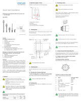
Fig. 7: Dimensioning of the thread
An uneven contact surface significantly reduces the accu-
racy of the signal within the frequency bandwidth
5.2 Sensor mounting and removal
For the mounting and removal of the sensor generally accepted
engineering practice must be followed. Particularly when work
is performed on electrical and pneumatic equipment any spe-
cial applicable safety regulations must be observed.
5.2.1 Mounting of the sensor
The sensor is installed with the mounting screws (M4x10)
which are included in the delivery content of the sensor.
The tightening torque must be 2.9 Nm.
High temperature screw paste Type 1059 must be applied
to the mounting screw.
Fig. 8: Blow up drawing of sensor installation

Uniaxial high temperature accelerometer Type 8205B...
8205B_002-798e-03.19_
Page 14
A heat shrink tube with the sensor labeling is included in
the delivery content of the sensor and can be placed at the
desired location on the cable and fixated by applying heat
to the shrink tube.
Werkstückkanten nach ISO 13715
-0,2
+0,25
Allgemeintoleranzen
Längenmasse
Abmasse
Winkelmasse kürz. Schenkel
Abmasse
...10
±0°20'
* ...0,5
> 10...50
>0,5...3
>120...400
>400..1000
±0°30'
>400...
±0,1 ±0,5
> 3...6
> 30...120
> 50...120
±0,3
±1°
±0,2 ±0,8
±0°10'
>120...400
*=KISTLER-Norm
±0,1
±0,05
> 6...30
±0° 5'
ISO 2768-mH
Zeichnung_A4_unbenannt
A4
1 / 1
1:1
measure. analyze. innovate.
Erstmals verwendet
Erste Proj.-Nr.
Werkstoff
Änderung
Datum
Massstab
Ersatz für
Kopie Datum
gez.
gepr.
ges.
Zeichnungs-Nr.
Material-Nr.
KIWAG-SWX_A4h
Ver.
Bl.
Das Urheberrecht an dieser Zeichnung, die dem Empfänger
persönlich anvertraut wird, verbleibt unserer Firma.
Ohne unsere schriftliche Genehmigung darf die Zeichnung
weder kopiert noch vervielfältigt, noch an Drittpersonen
mitgeteilt oder zugänglich gemacht werden.
Fig. 9: Heat shrink tube positioning
5.2.2 Sensor removal
If the sensor needs to be removed, make sure to not pull at
the cable but to grab the sensor body tightly while lifting it
upwards.
5.3 Cable handling and fixation
The integral cable is available in the following executions:
without extra protection
with steel overbraid
with spiral metal hose
with hermetic corrugated metal hose
For the installation the cable can be bent as needed. Please
make sure that
The minimal bending radius is not smaller than 16 mm
The cable is mechanically fixed
Cable movements should be avoided in order to prevent
triboelectric noise.
In case of a damaged cable, the sensor must be returned to
Kistler.
5.4 Electrical connections
The sensor is available with a cable termination of 3 open
leads. The standard lead length suits to Kistler charge ampli-
fier types 5181/5183/5185. For any special installation,
customer specific lead lengths are available.

Installation
Page 15
8205B_002-798e-03.19
Fig. 10: Cable termination, open leads
5.5 Electro mechanical connection
5.5.1 Connection to Kistler charge amplifier Type 5181 / 5183 / 5185
Werkstückkanten nach ISO 13715
-0,2
+0,25
Allgemeintoleranzen
Längenmasse
Abmasse
Winkelmasse kürz. Schenkel
Abmasse
...10
±0°20'
* ...0,5
> 10...50
>0,5...3
>120...400 >400..1000
±0°30'
>400...
±0,1 ±0,5
> 3...6
> 30...120
> 50...120
±0,3
±1°
±0,2 ±0,8
±0°10'
>120...400
*=KISTLER-Norm
±0,1±0,05
> 6...30
±0° 5'
ISO 2768-mH
KIWAG-SWX_A2q
Das Urheberrecht an dieser Zeichnung, die dem Empfänger
persönlich anvertraut wird, verbleibt unserer Firma.
Ohne unsere schriftliche Genehmigung darf die Zeichnung
weder kopiert noch vervielfältigt, noch an Drittpersonen
mitgeteilt oder zugänglich gemacht werden.
Zeichnung_A2_unbenannt
A2
1 / 1
1:2
measure. analyze. innovate.
Erstmals verwendet
Erste Proj.-Nr.
Werkstoff
Änderung
Datum
Massstab
Ersatz für Kopie Datum
gez.
gepr.
ges.
Zeichnungs-Nr.
Material-Nr.
Ver.
Bl.
Fig. 11: Connection of the sensor to Kistler charge ampli-
fier Type 5181 / 5183 / 5185
Werkstückkanten nach ISO 13715
-0,2
+0,25
Allgemeintoleranzen
Längenmasse
Abmasse
Winkelmasse kürz. Schenkel
Abmasse
...10
±0°20'
* ...0,5
> 10...50
>0,5...3 >120...400 >400..1000
±0°30'
>400...
±0,1 ±0,5
> 3...6 > 30...120
> 50...120
±0,3
±1°
±0,2 ±0,8
±0°10'
>120...400
*=KISTLER-Norm
±0,1±0,05
> 6...30
±0° 5'
ISO 2768-mH
KIWAG-SWX_A2q
Das Urheberrecht an dieser Zeichnung, die dem Empfänger
persönlich anvertraut wird, verbleibt unserer Firma.
Ohne unsere schriftliche Genehmigung darf die Zeichnung
weder kopiert noch vervielfältigt, noch an Drittpersonen
mitgeteilt oder zugänglich gemacht werden.
Zeichnung_A2_unbenannt
A2
1 / 1
1:2
measure. analyze. innovate.
Erstmals verwendet
Erste Proj.-Nr.
Werkstoff
Änderung Datum
Massstab
Ersatz für
Kopie Datum
gez.
gepr.
ges.
Zeichnungs-Nr.
Material-Nr.
Ver.
Bl.
Fig. 12: Section view of the connection

Uniaxial high temperature accelerometer Type 8205B...
8205B_002-798e-03.19_
Page 16
5.5.2 Connection through an obstruction
In many situations the cable of the accelerometer needs to
be fed through a wall or an enclosure in order to connect
it to the electronics; i.e. charge amplifier. Figures 13 to 16
show typical examples with recommended components.
(For instructions on how to put on these accessories to the
cable, please refer to the instruction leaflet provided with
the accessories.)
For further instructions on how to connect the cable
through an obstruction, please contact Kistler.
5.5.2.1 Adapter to charge amplifier for cables without cable protection, Type 1700A37B
Werkstückkanten nach ISO 13715
-0,2
+0,25
Allgemeintoleranzen
Längenmasse
Abmasse
Winkelmasse kürz. Schenkel
Abmasse
...10
±0°20'
* ...0,5
> 10...50
>0,5...3
>120...400 >400..1000
±0°30'
>400...
±0,1 ±0,5
> 3...6
> 30...120
> 50...120
±0,3
±1°
±0,2 ±0,8
±0°10'
>120...400
*=KISTLER-Norm
±0,1
±0,05
> 6...30
±0° 5'
ISO 2768-mH
A-A (1 : 1)
B-B (1 : 1)
KIWAG-SWX_A3q
Das Urheberrecht an dieser Zeichnung, die dem Empfänger
persönlich anvertraut wird, verbleibt unserer Firma.
Ohne unsere schriftliche Genehmigung darf die Zeichnung
weder kopiert noch vervielfältigt, noch an Drittpersonen
mitgeteilt oder zugänglich gemacht werden.
Bl.
Ver.
Material-Nr.
Zeichnungs-Nr.
ges.
gepr.
gez.
Kopie Datum
Ersatz für
Massstab
Datum
Änderung
Werkstoff
Erste Proj.-Nr.
Erstmals verwendet
measure. analyze. innovate.
1:5
1 / 1
A3
Zeichnung_A3_unbenannt
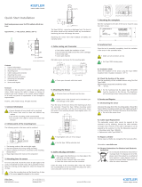
Fig. 13: Cable without protection
The cable feed through adapter Type 1700A37B is used with
the cable without extra protection.
Adapter
Type 1700A37B
Cable Gland
AGRO Part No.
1180.17.100
Cable w/o
protection
Inside enclosure

Installation
Page 17
8205B_002-798e-03.19
5.5.2.2 Adapter to charge amplifier for cables with steel overbraid, Type 1700A37C
Werkstückkanten nach ISO 13715
-0,2
+0,25
Allgemeintoleranzen
Längenmasse
Abmasse
Winkelmasse kürz. Schenkel
Abmasse
...10
±0°20'
* ...0,5
> 10...50
>0,5...3
>120...400
>400..1000
±0°30'
>400...
±0,1 ±0,5
> 3...6
> 30...120
> 50...120
±0,3
±1°
±0,2 ±0,8
±0°10'
>120...400
*=KISTLER-Norm
±0,1±0,05
> 6...30
±0° 5'
ISO 2768-mH
A-A (1 : 1)
B-B (1 : 1)
KIWAG-SWX_A3q
Das Urheberrecht an dieser Zeichnung, die dem Empfänger
persönlich anvertraut wird, verbleibt unserer Firma.
Ohne unsere schriftliche Genehmigung darf die Zeichnung
weder kopiert noch vervielfältigt, noch an Drittpersonen
mitgeteilt oder zugänglich gemacht werden.
Bl.
Ver.
Material-Nr.
Zeichnungs-Nr.
ges.
gepr.
gez.
Kopie Datum
Ersatz für
Massstab
Datum
Änderung
Werkstoff
Erste Proj.-Nr.
Erstmals verwendet
measure. analyze. innovate.
1:5
1 / 1
A3
Zeichnung_A3_unbenannt
Fig. 14: Cable with steel overbraid
Similarly the cable feed trough adapter Type 1700A37C is
used with the cable with steel overbraid. The electrome-
chanical contact between the cable overbraid and the cable
feed trough is enabled via the adapter.
5.5.2.3 Connection of the cable with spiral metal hose
Werkstückkanten nach ISO 13715
-0,2
+0,25
Allgemeintoleranzen
Längenmasse
Abmasse
Winkelmasse kürz. Schenkel
Abmasse
...10
±0°20'
* ...0,5
> 10...50
>0,5...3
>120...400 >400..1000
±0°30'
>400...
±0,1 ±0,5
> 3...6
> 30...120
> 50...120
±0,3
±1°
±0,2 ±0,8
±0°10'
>120...400
*=KISTLER-Norm
±0,1
±0,05
> 6...30
±0° 5'
ISO 2768-mH
A-A (1 : 1)
B-B (1 : 1)
KIWAG-SWX_A3q
Das Urheberrecht an dieser Zeichnung, die dem Empfänger
persönlich anvertraut wird, verbleibt unserer Firma.
Ohne unsere schriftliche Genehmigung darf die Zeichnung
weder kopiert noch vervielfältigt, noch an Drittpersonen
mitgeteilt oder zugänglich gemacht werden.
Bl.
Ver.
Material-Nr.
Zeichnungs-Nr.
ges.
gepr.
gez.
Kopie Datum
Ersatz für
Massstab
Datum
Änderung
Werkstoff
Erste Proj.-Nr.
Erstmals verwendet
measure. analyze. innovate.
1:5
1 / 1
A3
Zeichnung_A3_unbenannt
Connector included
in the cable solution
Reccommended 3rd
Party Product: AGRO
Part Nr. 1180.17.100
Fig. 15: Cable with spiral metal hose
Cable Gland
AGRO Part No.
1180.17.100
Adapter
Type 1700A37C
Cable with steel
overbraid
Inside enclosure
/
