Page is loading ...

Important Installation Notes
for Mold Cavity Pressure Sensors
Types 6152, 6153, 6157, 6158, 6159, 6167
6169, 6175, 6182, 6183, 6190

Introduction
The following questions often come up during the installa-
tion of mold cavity pressure sensors:
•Is the sensor functioning correctly?
•Are the measured values correct?
•Pressure differences were measured in the 4 cavities. Do
these differences actually exist or has a measuring error
occured?
A precondition for answering these questions is correct
sensor installation. Every sensor is calibrated before delive-
ry. The calibration data can be obtained from the calibra-
tion sheet supplied. If the sensor is poorly installed (jam-
med or twisted i.e. under force shunt loading), this will
have a negative influence on its measuring accuracy. The
effect of inadequate sensor installation will be particularly
significant in applications where there are several sensors in
one mold (e.g. multi-cavities).

Single-Wire Technology
In addition to the «conventional cable technique» (coaxial
cable with fixed lengths and fitted connectors), there is
now also the single wire technique, which has the follo-
wing significant advantages:
•Mold machining more cost-effective
•Cables can be installed in bores without the need to
machine channels
•Simple installation by self-fitting connectors
•Cables more flexibly installed as a result of their smaller
diameter
•Cables can be shortened to the actual length required
• Compatible with existing extension cables
•In the event of a cable breakage, you can carry out
repairs yourself
•Smaller cable dimensions result in big advantages in
multi-cavity applications
•Possibility of direct connection of the sensor cable to
multi-channel amplifiers using cut-and-clamp technique
The following notes should provide short and comprehen-
sible information on how to prevent installation errors (and
resulting faulty measurements).

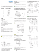
Illustration of a Sensor Installation
It is essential to use the dimensions in the data sheet or
operating instructions for the mounting bore. Do not try to
ascertain the dimensions yourself by measuring the sensor.

•The contact surface must be flat and at right angles to
the bore (optimum sensor contact surface).
•The bore must on no account be tapered. Tapered
bores must be further machined using a lapping tool and
lapping paste.
•Each time the contact surface of the bore /is further
machined, the 60° chamfer must be checked and
re-machined as necessary.
•The length of the bore must be matched to the sen-
sor, so that the front of the sensor comes flush with the
mold cavity wall.
•The sensor must always be center aligned through the
bore and on no account through the flange (threaded
bore for the mounting nut must be concentric).
•The bore outlet at the cavity wall must have sharp
edges (least possible impression on the molding).
After manufacturing the bore, it should be checked
against the above mentioned points. (e.g. using gages,
lapping tool, Kistler accessories kit Type 1300A83).

During installation, the sensor should be inserted into
the bore using an insertion and extraction tool, which
should then be used to extract it.
Secure the sensor by tightening the mounting nut with
a socket wrench.
The connector can be fitted to the mold with a mounting
plate or a clamping piece (countersunk). When the cable is
not connected, the protective cover should be fitted over
the connector.
The sensor identification plate included in the mold acces-
sories should be fitted close to the connector on the mold.
Installing and Removing the Sensor

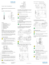
Installation Example with Spacer
Sleeve
The mounting nut included with larger sensors is not com-
pulsory. Installation is also possible with a spacer sleeve
with a slot at its side (for the cable exit). With very small
sensors (e.g. Types 6182A…/6183A…), preference should
be given to spacer sleeve mounting. The spacer sleeve is
often used when fitting sensors in prehardened inserts,
since this eliminates the need for an otherwise difficult to
machine thread.
This illustration shows a sensor fitted
with a spacer sleeve and «grub
screw». But this screw is not always
necessary. Usually, the sleeve is sup-
ported by a mold plate.
The sleeve length is normally selec-
ted so that a gap of up to about
0,02 mm remains.
Cable
Cable bore
0,02 mm

www.kistler.com
Switzerland
Kistler Instrumente AG
PO Box
CH-8408 Winterthur
Tel. (+41) 52 224 11 11
Fax (+41) 52 224 14 14
info@kistler.com
002-259e-04.03 Mat4000 ©2003, Kistler Instrumente AG
/

