Page is loading ...

Intelligent Data Logging Products
www.datataker.com
© 2017 ThermoFisher Scientific
DT80 Range
DT80/81/82/85
Series 1,2,3 & 4
Includes CEM20
User's Manual
A complete guide to:
data acquisition
data logging
programming
sensor wiring
communications

UM-0085-B11E DT80 Range User Manual Page 2
RGJKLJW
DT80 Range User’s Manual
© Copyright 2005-2018 Thermo Fisher Scientific Australia Pty Ltd ABN 52 058 390 917
UM-0085-B11E
Warranty
Thermo Fisher Scientific Australia Pty Ltd (“Thermo Fisher”) warrants the instruments it manufactures against defects in
either the materials or the workmanship for a period of three years from the date of delivery to the original customer.
This warranty is limited to, and purchaser’s sole remedy for a breach of this warranty is, the replacement or repair of
such defects, without charge, when the instrument is returned to Thermo Fisher or to one of its authorized dealers
pursuant to Thermo Fisher’s return policy procedures.
The obligations set forth above shall be void with respect to any damage to the instrument resulting from accident,
abuse, improper implementation or use, lack of reasonable care, loss of parts, force majeure, or any other third party
cause beyond Thermo Fisher’s control. Any installation, maintenance, repair, service, or alteration to or of, or other
tampering with, the instruments performed by any person or entity other than Thermo Fisher without its prior written
approval, or any use of replacement parts not supplied by Thermo Fisher, shall immediately void and cancel all
warranties with respect to the affected instruments.
Thermo Fisher shall not be liable for any incidental, indirect, special, punitive or consequential loss or damages resulting
from or arising out of the use of the instrument, In no event shall Thermo Fisher’s liability with respect to the instrument,
the use thereof, this warranty statement or any cause of action related thereto, under any circumstances exceed the
purchase price of the instrument actually paid by purchaser.
Where Thermo Fisher supplies to the customer equipment or items manufactured by a third party, then the warranty
provided by the third party manufacturer shall pass through to purchaser, but only to the extent allowed by the original
manufacturer or third party supplier.
EXCEPT AS EXPRESSLY PROVIDED IN THIS WARRANTY STATEMENT, THERMO FISHER DISCLAIMS ALL
OTHER WARRANTIES, WHETHER EXPRESS OR IMPLIED, ORAL OR WRITTEN, WITH RESPECT TO THE
INSTRUMENTS, INCLUDING WITHOUT LIMITATION ALL IMPLIED WARRANTIES OF MERCHANTABILITY OR
FITNESS FOR ANY PARTICULAR PURPOSE. THERMO FISHER DOES NOT WARRANT THAT THE INSTRUMENTS
ARE ERROR-FREE OR WILL ACCOMPLISH ANY PARTICULAR RESULT. ANY ADVICE OR ASSISTANCE
FURNISHED BY THERMO FISHER IN RELATION TO THE INSTRUMENTS SHALL NOT GIVE RISE TO ANY
WARRANTY OR GUARANTEE OF ANY KIND, AND SHALL NOT CONSTITUTE A WAIVER BY THERMO FISHER.
The Purchaser shall be solely responsible for complying with all applicable local, state and Federal laws with respect to
the installation, use and implementation of the equipment.
Trademarks
dataTaker is a registered trademark of Thermo Fisher Scientific Australia Pty Ltd
Adobe® Flash ® Player. Copyright © 1996 – 2006 Adobe Systems Incorporated. All Rights Reserved. Protected by U.S.
Patent 6,879,327; Patents pending in the United States and other countries. Adobe and Flash are either trademarks or
registered trademarks in the United States and/or other countries.
All other brand and product names are trademarks or registered trademarks of their respective holders.
Regulatory Notices
This equipment has been tested and found to comply with the limits for a Class A digital device, pursuant to part 15 of
the FCC Rules. These limits are designed to provide reasonable protection against harmful interference when the
equipment is operated in a commercial environment. This equipment generates, uses, and can radiate radio frequency
energy and, if not installed and used in accordance with the instruction manual, may cause harmful interference to radio
communications. Operation of this equipment in a residential area is likely to cause harmful interference in which case
the user will be required to correct the interference at his own expense.
Please refer to the following table and information for compliance requirements of the DT80 Series, CEM20 and internal
devices.
Domain
Applicable Standards
Safety (Product with Integrated Modem)
EN 60950.1:2006 +Amdt 11(2009), A1(2010), A12(2011) & A2(2013)
AS/NZS 60950.1:2011 +Amdt 1(2012)
EMC
EN 55032: 2015 + AC:2016
EN 55024:2010
EN 61000-3-2: Ed. 4.0 (2014)
EN 61000-3-3: Ed. 3.0 (2013)
ETSI EN 301 489-1 V1.9.2 (2011-09)
IC
CFR47 FCC Part 15, Subpart B (Class A)
FCC
CFR47 FCC Part 15, Subpart B (Class A)
China RoHs 2 – models without WiFi / Modem
Refer to China RoHs table below

UM-0085-B11E DT80 Range User Manual Page 3
RGJKLJW
FCC / IC Statements
This equipment has been tested and found to comply with the limits for a Class A digital device, pursuant to part 15 of
the FCC Rules. These limits are designed to provide reasonable protection against harmful interference when the
equipment is operated in a commercial environment. This equipment generates, uses, and can radiate radio frequency
energy and, if not installed and used in accordance with the instruction manual, may cause harmful interference to radio
communications. Operation of this equipment in a residential area is likely to cause harmful interference in which case
the user will be required to correct the interference at his own expense.
Changes or modifications not expressly approved by the party responsible for compliance could void the user's authority
to operate the equipment.
Cet équipement a été testé et reconnu conforme aux limites d'un appareil numérique de classe A, conformément à la
partie 15 des règles de la FCC. Ces limites sont conçues pour fournir une protection raisonnable contre les interférences
nuisibles lorsque l'équipement est utilisé dans un environnement commercial. Cet équipement génère, utilise et peut
émettre de l'énergie radiofréquence et, s'il n'est pas installé et utilisé conformément au manuel d'instructions, peut
causer des interférences nuisibles aux communications radio. Le fonctionnement de cet équipement dans une zone
résidentielle est susceptible de causer des interférences nuisibles, auquel cas l'utilisateur devra corriger l'interférence à
ses propres frais.
Les changements ou modifications non expressément approuvés par la partie responsable de la conformité pourraient
annuler l'autorisation de l'utilisateur d'utiliser l'équipement.
Dependent on model the product may contain
Modem (DT80LM3, DT82EM3, DT85M3, DT85GLM3) – FCC ID: RI7HE910 / IC ID: 5131A-HE910
WiFi Module (DT80W, DT80GW, DT85W, DT85GW) – FCC ID: XF6-RS9113SB / IC ID: 8407A-RS9113SB
China RoHs
Part or
Component
Name
零件或部件名称
Hazardous Substances
有害物质或元素
Lead (Pb)
铅
Mercury (Hg)
汞
Cadmium (Cd)
镉
Hexavalent
Chromium (Cr(VI))
六价铬
Polybrominated
Biphenyls (PBB)
多溴联苯
Polybrominated
Diphenyl Ethers (PBDE)
多溴二苯醚
Resistors
电阻
X
O
O
O
O
O
Standoffs
支座
X
O
O
O
O
O
Connectors
连接器
X
O
O
O
O
O
Fasteners
紧固件
X
O
O
O
O
O
Potentiometers
电位器
X
O
O
O
O
O
Memory Stick
记忆棒
X
O
O
O
O
O
Integrated Circuits
集成电路
X
O
O
O
O
O
This table is prepared in accordance with the provisions of SJ/T 11364.
本表格依据SJ/T 11364 的规定编制。
O : Indicates that the concentration of the hazardous substance in all homogeneous materials of the part is below the relevant
threshold of the GB/T 26572 standard.
O : 表示该有害物质在该部件所有均质材料中的含量均在 GB/T 26572 规定的限量要求以下。
X : Indicates that the concentration of the hazardous substance in at least one homogeneous material of the part is above the
relevant threshold of the GB/T 26572 standard.
X : 表示该有害物质至少在该部件的某一均质材料中的含量超出 GB/T 26572 规定的限量要求。
Marking Standard SJ/T 11364 requires this chart format for listed parts or components that exceed a maximum concentrated limit.
As a service to our customers, we are using the chart format to provide information regarding these part or components.
标识标准SJ / T 11364要求此图表格式列出超过最大浓度限制的零件或组件。作为对我们客户的服务,我们使用此图表格式提供有关
这些零件或组件的信息。
(Concentration limits are 0.1% for Lead, Mercury, Hexavalent Chromium, Polybrominated Biphenyls, Polybrominated Diphenyl
Ethers (excluding decaBDE), and 0.01% for Cadmium)
(铅,汞,六价铬,多溴联苯,多溴二苯醚(不包含十溴二苯醚)的浓度限制为 0.1%,以及镉为 0.01)
Environment Friendly Use Period (EFUP)
环保使用期限(EFUP)

UM-0085-B11E DT80 Range User Manual Page 4
RGJKLJW
Changes or modifications not expressly approved by the party responsible for compliance could void the user's authority
to operate the equipment.
Disposal of Product and Batteries
This product is subject to the EU Directive 2012/19/EU for Waste Electrical and Electronic Equipment
(WEEE). As such product must not be disposed of in general waste facilities. Please refer to local
regulations or contact your distributor on how to dispose this product in an environmentally friendly
manner.
Dispose of used batteries via an appropriate recycling facility only.
Warning
dataTaker products are not authorized for use as critical components in any life support system where failure of the
product is likely to affect the system’s safety or effectiveness.
This equipment is compliant with class A of EN55032. In residential environment this equipment may cause radio
interference.
Important: Firmware Version Covered in This Manual
This version of the dataTaker DT80 Range User’s Manual (UM-0085-B11E) applies to the DT80 range of data loggers
(DT80, DT80G, DT80L, DT80LM3, DT80GL, DT80W, DT82E, DT82EM3, DT82I, DT85, DT85G, DT85L, DT85LM3,
DT85GL, DT85W, DT85GW, and DT85GLM3, Series 1, 2, 3 and 4) running Version 9.20 firmware.

UM-0085-B11E DT80 Range User Manual Page 5
RGJKLJW
Content
Content ...................................................................................................................... 5
Part A – The DT80 ..................................................................................... 14
DT80 Concepts ........................................................................................................ 14
What is the DT80? ...................................................................................................................................... 14
The DT80 Product Family ........................................................................................................................... 14
DT80-Friendly Software .............................................................................................................................. 18
About This Manual ...................................................................................................................................... 18
A Tour of the DT80's Interfaces .................................................................................................................. 18
Getting Started ............................................................................................................................................ 19
Sending Commands.................................................................................................................................... 20
Getting Help ................................................................................................................................................ 21
Designing Your Data Logging System ........................................................................................................ 21
Measurements ......................................................................................................... 22
What can the DT80 Measure? .................................................................................................................... 22
Analog Channels – Introduction .................................................................................................................. 22
Digital Channels – Introduction ................................................................................................................... 25
Serial Channels – Introduction .................................................................................................................... 25
Programming the DT80 ........................................................................................... 26
Typical Workflow ......................................................................................................................................... 26
USB memory devices .................................................................................................................................. 28
Format of Returned Data ........................................................................................ 29
Real-time data ............................................................................................................................................. 29
Logged Data ............................................................................................................................................... 30
Part B – Channels ..................................................................................... 32
Channel Definitions ................................................................................................ 32
Channel Numbers ................................................................................................... 32
Channel Number Sequence ........................................................................................................................ 33
Channel Types ......................................................................................................... 33
Internal Channel Types ............................................................................................................................... 36
Channel Options ..................................................................................................... 40
Overview ..................................................................................................................................................... 40
A Special Channel Option — Channel Factor ............................................................................................. 41
Multiple Reports .......................................................................................................................................... 41
Mutually Exclusive Options ......................................................................................................................... 41
Order of Application .................................................................................................................................... 42
Default Channel Options ............................................................................................................................. 42
Channel Option Table ................................................................................................................................. 43
Part C – Schedules ................................................................................... 47
Schedule Concepts ................................................................................................. 47
What are Schedules? .................................................................................................................................. 47
Schedule Syntax ......................................................................................................................................... 47

UM-0085-B11E DT80 Range User Manual Page 6
RGJKLJW
Types of Schedules ................................................................................................ 50
General-Purpose Report Schedules ........................................................................................................... 50
Immediate Report Schedules ...................................................................................................................... 55
Statistical Report Schedules ....................................................................................................................... 56
Working with Schedules ......................................................................................... 57
Entering Schedules into the DT80 (BEGIN–END) ...................................................................................... 57
Triggering and Schedule Order ................................................................................................................... 57
Changing a Schedule Trigger ..................................................................................................................... 58
Halting & Resuming Schedules ................................................................................................................... 58
Executing Commands in Schedules............................................................................................................ 58
Time Triggers — Synchronizing to Midnight ............................................................................................... 59
Part D – Jobs ............................................................................................ 60
What is a Job? ............................................................................................................................................ 60
Entering a Job ............................................................................................................................................. 60
Loading an Existing Job .............................................................................................................................. 61
Job Structure ............................................................................................................................................... 61
Job Commands ........................................................................................................................................... 62
Startup Job .................................................................................................................................................. 63
ONINSERT Job ........................................................................................................................................... 63
Part E – Manipulating Data ...................................................................... 64
Scaling ..................................................................................................................... 64
Channel Factor ........................................................................................................................................... 64
Spans (Sn) .................................................................................................................................................. 64
Polynomials (Yn) ......................................................................................................................................... 65
Thermistor Scaling (Tn) ............................................................................................................................... 65
Intrinsic Functions (Fn) ................................................................................................................................ 66
Combining Scaling Options ......................................................................................................................... 66
Calculations ............................................................................................................. 66
Channel Variables (nCV) ............................................................................................................................ 66
Calculation Only Channels .......................................................................................................................... 68
Reference Channels ................................................................................................................................... 68
Expressions ................................................................................................................................................ 69
Running Average ........................................................................................................................................ 73
Derived Quantities .................................................................................................. 74
Rates and Integrals ..................................................................................................................................... 74
Edge Timing ................................................................................................................................................ 74
Statistical Channel Options .................................................................................... 75
Overview ..................................................................................................................................................... 75
Statistical Functions .................................................................................................................................... 76
Multi Value Statistical Options ............................................................................... 77
Histogram (Hx:y:m..nCV) ............................................................................................................................ 77
Rainflow Cycle Counting ............................................................................................................................. 78
Part F – Alarms ........................................................................................ 81
Alarm Concepts ....................................................................................................... 81
Alarm Commands ................................................................................................... 81
Alarm Number ............................................................................................................................................. 82
Alarm Condition .......................................................................................................................................... 82
Alarm Digital Action Channels ..................................................................................................................... 84

UM-0085-B11E DT80 Range User Manual Page 7
RGJKLJW
Alarm Action Text ........................................................................................................................................ 84
Alarm Communication Actions .................................................................................................................... 86
Alarm Action Processes .............................................................................................................................. 87
Alarm Records ......................................................................................................... 91
Real Time Alarm Return .............................................................................................................................. 91
Logging Alarms ........................................................................................................................................... 91
Polling Alarm Inputs ............................................................................................... 92
Part G – Logging and Retrieving Data .................................................... 93
Logging Data ........................................................................................................... 93
Enabling and Disabling Data Logging ......................................................................................................... 93
How Data and Alarms are Stored................................................................................................................ 93
Logging Options .......................................................................................................................................... 95
Factors Which May Prevent Logging .......................................................................................................... 95
Checking Logging Status ............................................................................................................................ 96
Retrieving Logged Data .......................................................................................... 97
Overview ..................................................................................................................................................... 97
LISTD – List Available Data ........................................................................................................................ 97
COPYD – Unload Data ............................................................................................................................. 100
DELD - Delete Logged Data ..................................................................................................................... 110
Background Commands ............................................................................................................................ 111
Obsolete Commands ................................................................................................................................ 112
The DT80 File System ........................................................................................... 113
Internal File System (B:) ............................................................................................................................ 113
External USB Devices (A:) ........................................................................................................................ 113
File Commands ......................................................................................................................................... 115
Data Recovery .......................................................................................................................................... 115
Part H – DT80 Front Panel ..................................................................... 117
Display ................................................................................................................... 117
Displaying Channels and Alarms .............................................................................................................. 117
Bar Graph ................................................................................................................................................. 118
Controlling what is shown on the display .................................................................................................. 118
Auto-scrolling ............................................................................................................................................ 119
Auto-acknowledge..................................................................................................................................... 119
Pop-up Messages ..................................................................................................................................... 119
Interactive Screens ................................................................................................................................... 119
Display Backlight ....................................................................................................................................... 119
User Defined Functions ........................................................................................ 120
Defining Functions .................................................................................................................................... 120
Selecting Functions ................................................................................................................................... 120
Default Functions ...................................................................................................................................... 120
Keypad operation .................................................................................................. 121
Special Key Sequences ............................................................................................................................ 121
Status Indicator Lights ......................................................................................... 121
Sample Indicator ....................................................................................................................................... 121
Disk Indicator ............................................................................................................................................ 121
Power Indicator ......................................................................................................................................... 121
Attn Indicator ............................................................................................................................................. 121

UM-0085-B11E DT80 Range User Manual Page 8
RGJKLJW
Part I – dEX ............................................................................................ 123
What is dEX? ............................................................................................................................................ 123
dEX vs. Classic Web Interface .................................................................................................................. 123
Connecting to the Web Interface ............................................................................................................... 123
dEX Home Page ....................................................................................................................................... 123
Starting dEX .............................................................................................................................................. 124
Browser Requirements .............................................................................................................................. 125
Back to the Main Menu (Home) ................................................................................................................ 125
dEX Configuration Builder ................................................................................... 125
Configure the logger.................................................................................................................................. 125
About Configurations................................................................................................................................. 125
Using the Configuration Builder ................................................................................................................ 125
Defining Schedules ................................................................................................................................... 127
Defining Channels ..................................................................................................................................... 129
Global Settings .......................................................................................................................................... 135
Managing Configurations .......................................................................................................................... 142
Logger Controls ........................................................................................................................................ 143
Preventing Configuration Changes ........................................................................................................... 143
dEX Web Interface ................................................................................................. 144
Using the Web Interface ............................................................................................................................ 144
Status Screens .......................................................................................................................................... 145
Data Retrieval ........................................................................................................................................... 147
Displaying Real-Time Measurements ....................................................................................................... 149
Command Window .................................................................................................................................... 156
Help ........................................................................................................................................................... 157
Customising the Web Interface ............................................................................ 158
Overview ................................................................................................................................................... 158
The Web Interface Configuration Tool ...................................................................................................... 158
Preventing Configuration Changes ........................................................................................................... 161
Enabling dEX User Level Authentication ................................................................................................... 161
dEX Languages ........................................................................................................................................ 164
Classic Web Interface ........................................................................................... 165
Browser Requirements .............................................................................................................................. 165
Navigating the Web Interface .................................................................................................................... 165
Home Page ............................................................................................................................................... 165
Channels Page ......................................................................................................................................... 166
Status Page .............................................................................................................................................. 166
Files Page ................................................................................................................................................. 167
Help Page ................................................................................................................................................. 167
Customising the Classic Interface ....................................................................... 168
Web Application Programming Interface (API) .......................................................................................... 168
Server-Side Include (SSI) Directives ......................................................................................................... 168
Building A Custom Web Page ................................................................................................................... 171
Part J – Modbus Interface ..................................................................... 173
About Modbus ........................................................................................................................................... 173
Connecting to a Modbus Network ............................................................................................................. 173
Modbus Registers ..................................................................................................................................... 174
Putting It All Together ................................................................................................................................ 177
Part K – Communications ...................................................................... 180
Overview ................................................................................................................ 180
Services .................................................................................................................................................... 180

UM-0085-B11E DT80 Range User Manual Page 9
RGJKLJW
Protocols ................................................................................................................................................... 180
Physical Ports ........................................................................................................................................... 181
About the Communications Diagram......................................................................................................... 181
The Command Interface ....................................................................................... 184
Connecting to the Command Interface ...................................................................................................... 184
Command Interface Operation .................................................................................................................. 184
Detecting DT80 Presence ......................................................................................................................... 184
Password Protection ................................................................................................................................. 184
USB Port ................................................................................................................ 185
Configuring the USB Port .......................................................................................................................... 185
About DtUsb .............................................................................................................................................. 185
Installing DtUsb ......................................................................................................................................... 186
Using DtUsb .............................................................................................................................................. 189
USB Direct Serial Mode ............................................................................................................................ 190
Sleep Mode ............................................................................................................................................... 191
RS-232 Communications ...................................................................................... 191
Direct RS-232 Connection ........................................................................................................................ 191
RS-232 Flow Control ................................................................................................................................. 191
Sleep Mode ............................................................................................................................................... 192
Host RS-232 Port ................................................................................................... 193
Configuring the Host RS-232 Port ............................................................................................................. 193
Serial Sensor Port ................................................................................................. 194
Connecting to the Serial Sensor Port ........................................................................................................ 195
Configuring the Serial Sensor Port ............................................................................................................ 196
External Modem .................................................................................................... 198
Modem (Remote) RS 232 Connection ...................................................................................................... 198
Automatic Modem Detection ..................................................................................................................... 198
DT80-to-Modem Cable .............................................................................................................................. 198
Modem Initialisation .................................................................................................................................. 199
Powering the DT80’s Modem .................................................................................................................... 201
Modem Communications Operation .......................................................................................................... 201
Setting Up a Remote Connection .............................................................................................................. 202
Part L – Network Communications ....................................................... 203
TCP/IP Concepts ................................................................................................... 203
About TCP/IP ............................................................................................................................................ 203
About This Section .................................................................................................................................... 203
TCP/IP Parameters ................................................................................................................................... 204
Integrated Modem ................................................................................................. 205
Mobile Plans ............................................................................................................................................. 206
Getting Started .......................................................................................................................................... 208
Configuring the Integrated Modem ............................................................................................................ 209
Verifying Modem Operation ...................................................................................................................... 213
Troubleshooting and Advanced Configuration .......................................................................................... 215
Communications Sessions .................................................................................. 220
Session Timing ......................................................................................................................................... 220
Error handling ........................................................................................................................................... 222
Session Diagnostics .................................................................................................................................. 225
Ethernet Sessions ..................................................................................................................................... 227
Ethernet Communications.................................................................................... 229
Connecting to the DT80 Ethernet Port ...................................................................................................... 229
Ethernet Commands ................................................................................................................................. 230

UM-0085-B11E DT80 Range User Manual Page 10
RGJKLJW
How to set up Ethernet .............................................................................................................................. 232
Accessing the DT80 via the Internet ......................................................................................................... 235
WiFi Communications .......................................................................................... 238
WiFi Interface ............................................................................................................................................ 238
WiFi Commands........................................................................................................................................ 238
Setting up WiFi Connection ....................................................................................................................... 242
PPP Communications ........................................................................................... 244
About PPP ................................................................................................................................................ 244
Setting up PPP .......................................................................................................................................... 244
Using PPP ................................................................................................................................................. 250
Network Services .................................................................................................. 251
Using the Network Command Interface .................................................................................................... 251
Using the DT80 FTP Server ...................................................................................................................... 252
Security .................................................................................................................. 254
Basic Security ........................................................................................................................................... 254
dEX Security ............................................................................................................................................. 255
Part M – Configuration ........................................................................... 256
Configuring the DT80 ............................................................................................ 256
Parameters ............................................................................................................................................... 256
Switches .................................................................................................................................................... 258
Profile Settings .......................................................................................................................................... 260
Command Server Timeout Profile ............................................................................................................. 265
Setting the System Time ........................................................................................................................... 265
Automatic Time Adjustment (NTP) ............................................................................................................ 266
Resetting the DT80 ................................................................................................ 269
Soft Reset ................................................................................................................................................. 269
Hard Reset ................................................................................................................................................ 269
Safe Mode ................................................................................................................................................. 270
Factory Settings ........................................................................................................................................ 270
Diagnostic Commands ......................................................................................... 271
TEST Command ....................................................................................................................................... 271
Event Logs ................................................................................................................................................ 272
STATUS Command .................................................................................................................................. 272
CHARAC Command ................................................................................................................................. 273
SERVICEDATA Command ....................................................................................................................... 273
Part N – Hardware & Power ................................................................... 274
Inputs and Outputs ............................................................................................... 274
Wiring Panel .............................................................................................................................................. 274
Left Side Panel .......................................................................................................................................... 275
Right Side Panel (DT8xM only) ................................................................................................................. 276
Right Side Panel (DT8xW only) ................................................................................................................ 276
Front Panel ............................................................................................................................................... 276
Rear Panel (DT8xG only) .......................................................................................................................... 276
Inside the DT80 ...................................................................................................... 277
Accessing the main battery (if fitted) ......................................................................................................... 277
Accessing the lithium memory backup battery .......................................................................................... 278
Installation ............................................................................................................. 280
Dimensions ............................................................................................................................................... 280
Operating Environment ............................................................................................................................. 280

UM-0085-B11E DT80 Range User Manual Page 11
RGJKLJW
Grounding ................................................................................................................................................. 281
Powering the DT80 ................................................................................................ 281
Power Subsystem ..................................................................................................................................... 281
External Power .......................................................................................................................................... 282
Internal Power ........................................................................................................................................... 283
Power Outputs .......................................................................................................................................... 285
Signal Output ............................................................................................................................................ 286
Internal Memory-Backup Battery ............................................................................................................... 286
Monitoring DT80 Power ............................................................................................................................ 287
Power Consumption ............................................................................................. 287
Power Consumption .................................................................................................................................. 287
Battery Life ................................................................................................................................................ 292
Minimising Power Consumption ................................................................................................................ 293
Sleep Mode ............................................................................................................ 295
About Sleep Mode..................................................................................................................................... 295
Wake Events ............................................................................................................................................. 295
Controlling Sleep ....................................................................................................................................... 295
Forced Sleep Mode ................................................................................................................................... 296
Part O – Sensors & Channels ................................................................ 297
Analog Channels ................................................................................................... 297
About the Analog Input Terminals ............................................................................................................. 297
Voltage ...................................................................................................................................................... 298
Current ...................................................................................................................................................... 301
4–20mA Current Loops ............................................................................................................................. 303
Resistance ................................................................................................................................................ 303
Bridges ...................................................................................................................................................... 306
Temperature – Thermocouples ................................................................................................................. 310
Temperature – Thermistors ....................................................................................................................... 312
Temperature – RTDs ................................................................................................................................ 314
Temperature – AD590 Series IC Sensors ................................................................................................. 314
Temperature – LM35 Series IC Sensors ................................................................................................... 316
Temperature – LM135 Series IC Sensors ................................................................................................. 317
Humidity Sensors ...................................................................................................................................... 318
Frequency ................................................................................................................................................. 318
Strain Gauges – Bridge ............................................................................................................................. 319
Strain Gauges – Vibrating Wire ................................................................................................................. 320
Strain Gauges – Carlson Meter ................................................................................................................. 322
Digital Channels .................................................................................................... 326
About the Digital I/O Channels .................................................................................................................. 326
Digital Inputs ............................................................................................................................................. 327
Digital Outputs .......................................................................................................................................... 328
Counters – Low Speed .............................................................................................................................. 332
Counters – High Speed ............................................................................................................................. 333
Phase Encoders ........................................................................................................................................ 335
Examples – Digital and Counters .............................................................................................................. 336
SDI-12 Channel ...................................................................................................... 337
About SDI-12 ............................................................................................................................................ 337
Testing and Configuring an SDI-12 Device ............................................................................................... 338
Reading Data from SDI-12 Devices .......................................................................................................... 338
Example .................................................................................................................................................... 340
Other Considerations ................................................................................................................................ 341
Troubleshooting ........................................................................................................................................ 341

UM-0085-B11E DT80 Range User Manual Page 12
RGJKLJW
Generic Serial Channel ......................................................................................... 343
Connecting to and Configuring the Serial Port .......................................................................................... 343
Serial Channel Commands ....................................................................................................................... 343
Serial Channel Operation .......................................................................................................................... 344
Control String – Output Actions ................................................................................................................. 346
Control String – Input Actions ................................................................................................................... 348
Control String – Example .......................................................................................................................... 350
Schedules ................................................................................................................................................. 350
Serial Sensor Direct Mode ........................................................................................................................ 351
Serial Interface Power Control .................................................................................................................. 352
Serial Channel Debugging Tools .............................................................................................................. 352
Serial Channel Examples .......................................................................................................................... 353
Modbus Channel ................................................................................................... 356
About Modbus ........................................................................................................................................... 356
Connecting Serial Modbus Sensors .......................................................................................................... 356
Connecting Network Modbus Sensors ...................................................................................................... 357
Reading Data from Modbus Devices......................................................................................................... 358
MODBUS Channel Options ....................................................................................................................... 359
Block Transfers ......................................................................................................................................... 360
Examples .................................................................................................................................................. 361
Troubleshooting ........................................................................................................................................ 361
Technical Details & Troubleshooting .................................................................. 363
DT80 Analog Sub-System ......................................................................................................................... 363
Grounds, Ground Loops and Isolation ...................................................................................................... 367
Noise Pickup ............................................................................................................................................. 368
Self-Heating of Sensors ............................................................................................................................ 368
Getting Optimal Speed from Your DT80 ................................................................................................... 369
Part P – The CEM20 ............................................................................... 370
What is the CEM20? ................................................................................................................................. 370
Connecting CEM20s ................................................................................................................................. 370
CEM20 Addresses .................................................................................................................................... 372
Powering the CEM20 ................................................................................................................................ 372
Accessing CEM20 Channels ..................................................................................................................... 372
CEM20 Temperature Reference ............................................................................................................... 373
Troubleshooting ........................................................................................................................................ 373
Part Q – Reference ................................................................................. 374
DT80 Series Specifications .................................................................................. 374
Analog Inputs ............................................................................................................................................ 374
Digital Inputs and Outputs ......................................................................................................................... 375
High Speed Counter Inputs ....................................................................................................................... 376
Serial Channels ......................................................................................................................................... 376
Data Manipulation and Logging ................................................................................................................ 377
Communication Interfaces ........................................................................................................................ 377
Network (TCP/IP) Services ....................................................................................................................... 378
System ...................................................................................................................................................... 379
CEM20 Specifications ........................................................................................... 380
Command Summary ............................................................................................. 381
ASCII-Decimal Table ............................................................................................. 384

UM-0085-B11E DT80 Range User Manual Page 13
RGJKLJW
RS-232 .................................................................................................................... 387
Signals ...................................................................................................................................................... 387
Cables ....................................................................................................................................................... 387
Upgrading DT80 Firmware.................................................................................... 389
Recommended Preparation ...................................................................................................................... 389
Firmware Upgrade – USB Flash Device ................................................................................................... 390
Firmware Upgrade – Host USB or RS232 Port ......................................................................................... 390
Firmware Upgrade – Remote TCP/IP ....................................................................................................... 391
Reverting Back to Old Firmware ............................................................................................................... 391
In Case of Failed Upgrade ........................................................................................................................ 391
Upgrading Modem Firmware ..................................................................................................................... 391
Error Messages ..................................................................................................... 392
Standard Messages .................................................................................................................................. 392
Data Errors ................................................................................................................................................ 396
DT80 Abnormal Resets ............................................................................................................................. 397
Glossary ................................................................................................................. 398
Safety Information ................................................................................................. 409
General ..................................................................................................................................................... 409
Models with Internal Lead Acid Battery ..................................................................................................... 409
Models with Integrated Modem/ Integrated WiFi ....................................................................................... 409
Index ....................................................................................................................... 410

UM-0085-B11E DT80 Range User Manual Page 14
RGJKLJW
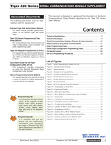
Part A – The DT80
Figure 1: The dataTaker DT80, DT80W (left); DT85W, DT85GM, CEM20 (centre), DT82EM, DT82I (right)
DT80 Concepts
What is the DT80?
The dataTaker DT80 range of data acquisition and logging instruments are tools to measure and record a wide variety of
quantities and values in the real world.
The web based dEX graphical user interface makes it quick and easy to define basic measurement tasks. Logged data
can then be easily extracted via a USB "memory stick", or downloaded using the web interface into files ready for import
into spreadsheets and data analysis tools.
The DT80 range of loggers also include a powerful programming language which allows complex systems to be
developed and monitored.
Extensive sensor support and communications options, and a rugged and low-power design, make the DT80 a very
flexible data logger.
The DT80 Product Family
Models
The DT80 product family includes the following models:
The DT80 is a full-featured data logger,
The DT82E is a low cost, low power logger designed for environmental applications.

UM-0085-B11E DT80 Range User Manual Page 15
RGJKLJW
The DT82I is designed for industrial applications.
The DT85 is an expanded and enhanced version of the DT80.
The DT80L and DT85L are low power variants of the DT80 and DT85.
The DT80W and DT85W are WiFi variant of the DT80 and DT85.
The DT80G and DT85G GeoLoggers are designed for Geotechnical applications
The DT80GW and DT85GW are WiFi variant of the DT80G and DT85G.
The DT80GL and DT85GL are low power variants of the DT80G and DT85G.
The DT82EM3, DT80LM3, DT85LM3 and DT85GLM3 contain an inbuilt GSM/EDGE/WCDMA cellular modem.
The DT82EM2, DT80LM2, DT85LM2 and DT85GLM2 contain an inbuilt GSM/EDGE cellular modem.
The CEM20 (Channel Expansion Module) is a 20-channel analog multiplexer which can be used to expand the
number of analog input channels on a DT80 or DT85.
All of these models operate in a similar way; the differences are mainly to do with the number of input channels and other
hardware features. Table 1 (P16) and
Table 2 (P17) lists the main differences between each model.
Series 1, 2, 3 and 4
In January 2008, the original DT80, DT81 and DT85 models were superseded by enhanced Series 2 models. These
offered an all-new web based interface (dEX), additional power outputs, and more flexible analog input switching.
Series 3 models were introduced from October 2010. These supersede Series 2 and include enhanced resistance
measurement options and an isolated switched 5V power output.
Series 4 were launched from February 2017 and include increased voltage and resistance measurement ranges, flexible
12/ 5V power outputs and integrating with DAC converter to produce voltage/ current outputs as well as WiFi connectivity
support.
Along with DT80 Series 4 launch the new CEM20 Series 2 has also been released. In CEM20 Series 2 all mechanical
relays has been replaced by opto-relays. As result all audible noise from the mechanical relay switching was eliminated.
Series 2, 3 and 4 units are clearly labelled as such on the front panel. When a logger model number is displayed, the
series is shown as a suffix, e.g. "DT85L-3" is a Series 3 DT85L.
GeoLoggers
The DT80G/GL and DT85G/GL "GeoLoggers" are equivalent to the DT80 and DT85, but also include direct support for
vibrating wire strain gauges, which are widely used in geotechnical applications; see Strain Gauges – Vibrating Wire
(P320). Throughout this manual, references to the DT80 and DT85 also refer to the DT80G and DT85G respectively,
unless otherwise noted.
Low Power Models
Most DT80 models include an internal 6V lead acid battery. However the low power "L" and "E" models do not include
an internal battery and are instead optimised for operation with an external battery (often solar charged). Throughout this
manual, references to the DT80 and DT85 also refer to the DT80L and DT85L respectively, unless otherwise noted.
Modem Models
The "M" models (DT82EM, DT80LM, DT85LM, DT85GLM) include an integrated cellular modem, which provides a
convenient wireless solution for control of the DT80 and data retrieval. The "M3" models support 2G and 3G networks
(GSM/ GPRS/ EDGE/ WCDMA), while the "M2" models support 2G only (GSM/ GPRS/ EDGE). Apart from this
difference, the M2 and M3 variants operate identically.
WiFi Models
The "W" models (DT80W, DT80GW, DT85W, DT85GW) include an integrated WiFi interface, which provides a
convenient wireless solution for control of the DT80 and data retrieval. See WiFi Communications (P238).
Channel Expansion Module
The CEM20 is an analog multiplexer designed to work with a DT80 or DT85 Series 2 logger and later revisions. It
provides an easy way to expand the number of input channels. Up to 16 CEM20 modules can be connected to a DT85,
giving a total of 320 input channels. See The CEM20 (P370).
Note: In this manual, the term DT80 (italics) is used to refer to all products (DT80, DT81, DT82 and DT85; Series 1, 2, 3 and 4). If a
feature or behaviour is specific to a particular model, this will be made clear in the text.

UM-0085-B11E DT80 Range User Manual Page 16
RGJKLJW
Feature
DT81-1
DT80-1
DT85-1
DT81-2
DT82E-2
DT82I-2
DT80-2
DT80G-2
DT85-2
DT85G-2
DT82E-3
DT82EM2-3
DT82EM3-3
DT82I-3
DT80-3
DT80G-3
DT80L-3
DT80LM2-3
DT80LM3-3
DT80GL-3
DT85-3
DT85G-3
DT85L-3
DT85LM2-3
DT85LM3-3
DT85GL-3
DT85GLM2-3
DT85GLM3-3
discontinued models
Analog input channels
1
5
16
1
2
2
5
5
16
16
2
2
2
2
5
5
5
5
5
5
16
16
16
16
16
16
16
16
Fully isolated analog input pairs (+- and *#
terminals switched independently)
-
-
2-wire resistance measurements on *#, +# and -
# terminal pairs
-
-
-
-
-
-
-
-
-
-
Vibrating wire strain gauge support
-
-
-
-
-
-
-
-
-
-
-
-
-
-
-
-
-
-
-
-
CEM20 modules supported
-
-
-
-
-
-
5
5
16
16
-
-
-
-
5
5
5
5
5
5
16
16
16
16
16
16
16
16
Digital I/O channels (open-drain outputs)
3
4
4
3
3
4
4
4
4
4
3
3
3
4
4
4
4
4
4
4
4
4
4
4
4
4
4
4
Digital I/O channels (logic outputs / SDI-12)
1
4
4
1
1
-
4
4
4
4
1
1
1
-
4
4
4
4
4
4
4
4
4
4
4
4
4
4
High speed counter inputs
4
4
4
4
4
4
4
4
4
4
4
4
4
4
4
4
4
4
4
4
7
4
7
7
7
4
7
7
Phase encoder inputs
1
2
2
1
-
2
2
2
2
2
-
-
-
2
2
2
2
2
2
2
3
2
3
3
3
2
3
3
RS232/422/485 communications port
-
-
-
-
-
-
RS232 communications port
-
-
-
-
-
-
-
-
USB communications port
-
-
-
-
-
-
Ethernet port
Integrated GSM/GPRS/EDGE/WCDMA modem
-
-
-
-
-
-
-
-
-
-
-
-
-
-
-
-
-
-
-
-
-
-
-
-
Integrated GSM/GPRS/EDGE modem
-
-
-
-
-
-
-
-
-
-
-
-
-
-
-
-
-
-
-
-
-
-
-
-
USB memory device port
Switched 12V power output
-
-
Unswitched external power output
-
-
-
-
-
-
-
-
-
-
-
-
-
-
-
-
-
Switched isolated 5V power output
-
-
-
-
-
-
-
-
-
-
Battery charger for internal/external battery
-
-
-
-
-
-
-
-
-
-
-
-
-
-
Internal battery (capacity in Ah)
1.2
1.2
4.0
1.2
-
1.2
1.2
-
4.0
4.0
-
-
-
1.2
1.2
-
-
-
-
-
4.0
4.0
-
-
-
-
-
-
Modbus master function
-
-
-
-
-
-
LCD display & keypad
-
-
Status LEDs
4
3
4
4
4
4
4
4
4
4
4
4
4
4
4
4
4
4
4
4
4
4
4
4
4
4
4
4
Classic web interface (HTML)
dEX Enhanced web interface (Flash)
-
-
-
WiFi Connectivity
-
-
-
-
-
-
-
-
-
-
-
-
-
-
-
-
-
-
-
-
-
-
-
-
-
-
-
-
Voltage/ Current Output
-
-
-
-
-
-
-
-
-
-
-
-
-
-
-
-
-
-
-
-
-
-
-
-
-
-
-
-
Table 1: Feature listing for DT80 data logger Series 3 and older

UM-0085-B11E DT80 Range User Manual Page 17
RGJKLJW
Table 2: Feature listing for DT80 data logger Series 4
Feature
DT82E- 4
DT82EM3- 4
DT82I- 4
DT80- 4
DT80G- 4
DT80M3- 4
DT80W-4
DT80GW-4
DT85- 4
DT85G- 4
DT85M3- 4
DT85GM3- 4
DT85W-4
DT85GW-4
Current models
Analog input channels
2
2
2
5
5
5
5
5
16
16
16
16
16
16
Fully isolated analog input pairs (+- and *#
terminals switched independently)
2-wire resistance measurements on *#, +# and -#
terminal pairs
Vibrating wire strain gauge support
-
-
-
-
-
-
-
-
-
CEM20 modules supported
-
-
-
5
5
5
5
5
16
16
16
16
16
16
Digital I/O channels (open-drain outputs)
3
3
4
4
4
4
4
4
4
4
4
4
4
4
Digital I/O channels (logic outputs / SDI-12)
1
1
-
4
4
4
4
4
4
4
4
4
4
4
High speed counter inputs
4
4
4
4
4
4
4
4
7
4
7
7
7
4
Phase encoder inputs
-
-
2
2
2
2
2
2
3
2
3
3
3
2
RS232/422/485 communications port
-
-
RS232 communications port
-
-
-
-
USB communications port
-
-
-
Ethernet port
Integrated GSM/GPRS/EDGE/WCDMA modem
-
-
-
-
-
-
-
-
-
-
Integrated GSM/GPRS/EDGE modem
-
-
-
-
-
-
-
-
-
-
-
-
-
-
USB memory device port
Switched 12V power output
Unswitched external power output
-
-
-
-
-
-
-
-
Switched isolated 5V power output
-
-
-
-
-
-
-
-
-
-
-
-
-
-
Battery charger for internal/external battery
-
-
-
-
-
Internal battery (capacity in Ah)
-
-
1.2
1.2
-
-
1.2
-
4.0
4.0
-
-
4.0
4.0
Modbus master function
-
-
LCD display & keypad
Status LEDs
Classic web interface (HTML)
dEX Enhanced web interface (Flash)
WiFi Connectivity
-
-
-
-
-
-
-
-
-
-
Voltage/ Current Output

UM-0085-B11E DT80 Range User Manual Page 18
RGJKLJW
DT80-Friendly Software
Programming and Configuration
There are three main ways to set up and program the DT80.
dEX is a web based application for programming and monitoring DT80 Series 2/ 3/ 4 data loggers. dEX is built
into the logger (no installation required) and runs in your web browser. It provides a totally graphical interface,
which means that knowledge of the dataTaker programming language is not required. Channels and schedules
are defined simply by clicking on icons and making selections from menus and dialog boxes; dEX will then
generate the required DT80 program and load it onto the logger.
Alternatively, commands entered interactively and then sent to the DT80 via one of its comms ports or a TCP/IP
network. This allows full access to the DT80's capabilities. DeTransfer, or the enhanced web interface's
command window, are the best tools for the job here. They both have separate send and receive windows, a
macro facility, and many other useful features. A standard terminal program (e.g. HyperTerminal) can also be
used.
Finally, you can develop a DT80 program off-line (e.g. using a text editor), then transfer it to the DT80 using a
USB memory device or send it as a file using DeTransfer.
Viewing Data and Status
Once the DT80 has been set up, there are a number of options for retrieving data and monitoring status:
The DT80's inbuilt web interface (dEX) provides a convenient way to access current data values and status
information from any web browser. dEX is available on Series 2, 3 and 4 loggers.
A simple HTML-based web interface is also provided on all loggers. This can be customized if required to
provide an application-specific user interface. This interface is designed to operate efficiently on slow
communications networks or on portable devices with a small display screen.
DeTransfer can be used to view real-time and logged data in text format.
dataTaker Instrument driver for LabVIEW™ is a set of drivers and documentation which allows dataTaker
data loggers to be incorporated in a LabVIEW environment. LabVIEW is National Instruments' industry-leading
graphical software development environment for measurement and automation applications.
All software is provided on the CD supplied with your DT80, and updates are available from the dataTaker website,
www.datataker.com (Support/ Downloads section).
About This Manual
This manual is intended for all users of the DT80. It describes:
How to connect sensors and other devices to the DT80's input and output channels.
How to program the DT80 to collect and return data as required.
How to manage the data that the DT80 collects.
The main focus of this manual will be on directly programming the DT80 using its command language. However, most of
the concepts discussed here also apply when building programs using tools such as dEX.
A Tour of the DT80's Interfaces
The DT80's interfaces with the outside world are grouped into three main areas: user interface (top), sensor interface
(front) and communications interface (side). See also Inputs and Outputs (P274).
User Interface
On the top panel of the DT80 you will find controls which allow the user to interact with the unit during operation – without
requiring a host computer:
A 2-line LCD display shows status messages, measured values, and a menu of pre-defined functions (not
DT81)
Six keypad buttons allow the user to navigate between the various displayed options (not DT81)
Four status LEDs are provided – the blue Sample LED flashes each time a measurement is taken, the green
Disk LED indicates internal flash disk activity, and the red Attn LED indicates various warning conditions, and
the green Power LED flashes at 3 second intervals while the logger is powered and not in low "sleep" mode.
The duty cycle of the flash indicates whether the logger is externally powered (long flashes) or running from its
internal battery (short flashes).
Note: Power LED is not present on DT80 Series 1.
A USB socket allows connection of a USB memory device, which provides a convenient way to retrieve data
from the DT80 (or load a program onto it).

UM-0085-B11E DT80 Range User Manual Page 19
RGJKLJW
Sensor Interface
On the sloping front panel of the DT80 there are two rows of terminal blocks – digital channels on the left, analog
channels on the right. The green terminal blocks can be quickly unplugged from the DT80 without unscrewing the sensor
cabling. This interface includes:
8 digital input/ output/ counter channels (1D–8D), 4 of which are SDI-12 compatible (DT82I: 4 channels; DT81/
82E: 4 channels, one of which is SDI-12 compatible)
an input to wake the DT80 from low power "sleep" mode (WK)
4 high speed counter inputs (7 on DT85/ 85L Series 3) (1C–4C)
2 phase encoder inputs, shared with the counter inputs connected) (1PE–2PE) (one phase encoder input on
DT81, none on DT82E, 3 on DT85/ 85L Series 3)
a pair of voltage free relay contact outputs (RELAY A and B)
a general purpose switched 12V 150mA power output (12V) (DT80/ 81/ 82E and DT85 Series 2/3 only)
a general purpose switched 12V/5V 300mA power output (12V/5V) (DT80/ 82E, DT85 Series 4 only)
a general purpose current limited (300mA) power output (PWR OUT), which is derived from the external power
input (DT85 only)
an isolated switched 5V power output (5V SW) (Series 3 only)
an isolated programmable 16-bit voltage and current output (V/I DAC) (Series 4 only)
digital / power ground terminals (DGND)
an RS232/422/485 compatible serial port (Tx, Rx, RTS and CTS) (not present on DT81/ 82E)
a number of analog input channels (5 channels for DT80, 1 channel for DT81, 16 channels for DT85)
an external excitation input (EXT *)
isolated analog ground terminals (AGND on DT80/81, EXT# on DT80 Series 2 and DT85)
Note: early production DT80 models only had 4 analog inputs
Communications/ Power Interface
On the left side panel you have a variety of connectivity options:
10-Base-T Ethernet for connection to a host computer or local area network
USB for high speed connection to a host computer (not present on DT82)
RS232 for connection to host computer or modem (not present on DT8xM)
two alternative DC power connectors – a standard plug-pack socket (DC jack) and a 4-pin terminal block (2-pin
for DT82E/ 80L/ 85L)
For more details, see Communications (P180)
Wireless Modem Interface (DT8xM only)
On the right side panel are the integrated modem interface:
SIM card slot (subscriber identity module)
Red status LED
Coaxial screw connector for optional "receive diversity" antenna (DT8xM3 only)
Coaxial screw connector for main antenna.
A threaded earth point is also available on both left and right side panels. See Grounding (P281).
WiFi Interface (DT8xW only)
On the right side panel are the integrated WiFi interface:
Coaxial screw connector for main antenna.
A threaded earth point is also available on both left and right side panels. See Grounding (P281).
Getting Started
Power
Powering the DT80 (P281) discusses the ways to provide power to the DT80. The simplest option is to plug in the
supplied AC adaptor.
All DT80 models except the DT82E include an internal 6V lead-acid battery which can power the logger if the main
external supply is interrupted.
Important: The DT80 is shipped with its main internal battery disconnected. We recommend the battery is connected as soon as
practical so that it can charge from the mains adaptor or other external power source. This is achieved by simply plugging the green
power connector, see Powering the DT80 (P281).

UM-0085-B11E DT80 Range User Manual Page 20
RGJKLJW
Switch On!
When power is connected, you should observe:
the LCD backlight switches on (DT80/ 85), and the green Power LED starts flashing
a brief clicking sound as the unit performs an initial self-calibration
DT80 restarted / Power loss is displayed on the LCD
the front panel LEDs flash a few times then the red Attn LED continues to flash.
The DT80 is warning you that its power has been interrupted. Press any of the front panel keys to clear this indication.
The Attn LED should stop flashing and the display should now read: DT80 V9.20 / No current job. This indicates
that:
the version of DT80 firmware in use is "9.20" (this number may vary), and
no user program (or "job") has been loaded
The DT80 is now idle and waiting for instructions.
Connecting to a Host Computer
In order to program the DT80, it is generally necessary to connect it to a "host" computer. The easiest option here is to
use the supplied USB cable, or, for the DT82E/82I, the supplied Ethernet cable. Other options are to use a "null-modem"
(cross-over) RS232 cable, or to connect the logger to an Ethernet network. See Communications (P180) for more details
of the different communications options.
Very briefly, connecting the DT80 via USB involves the following steps:
1. Install the supplied DTUsb driver software. This allows you to access to DT80's network services via a USB
connection.
2. Connect the USB cable between the DT80 and the PC.
3. The Windows "New Hardware Found" wizard will then run automatically (if required) to complete the installation
of the necessary drivers.
4. Your default web browser will then be launched automatically and the dEX home page will be displayed.
To connect to the DT80 using Ethernet:
1. Connect the Ethernet cable between the DT80 and the PC, or between the DT80 and a socket on your
computer's local area network.
2. Use the DT80 keypad to scroll down to the "Ethernet" screen. Check that a valid IP address is displayed, e.g.
169.254.3.202
3. Launch your web browser and type the logger's IP address into the address bar. The dEX home page should
be displayed.
The above is only a brief overview. See USB Port (P185) for detailed, step by step instructions.
As an alternative to the dEX web-based interface, you can also install the supplied DeTransfer software, which can be
used to send the text-based commands described in this manual to the logger. DeTransfer can operate over a direct
RS232/ USB connection or a network connection, and will work with any logger model.
The remainder of this manual will assume you have successfully established a connection between the host PC and the
DT80.
Sending Commands
The DT80 is programmed by sending it textual commands. These commands may be either:
Manually entered (using DeTransfer, or the Command screen in dEX), or
Generated by the dEX configuration builder, based on details entered using its graphical user interface controls.
Commands are executed by the DT80 only after it receives a carriage-return character ().
Commands are not case-sensitive; that is, they may be entered using either uppercase or lowercase characters.
In this manual all commands are shown in UPPERCASE. Responses from the DT80 are shown like this.
After receiving a command, the DT80 will normally echo the command, after converting it to uppercase. After a command
has been processed, the DT80 will normally indicate that it is ready for the next one by transmitting a prompt string,
such as:
DT80>
Note: the DT80 does not echo each character as it is received.
Command echo and the prompt string can be turned off if required using the /e switch command, see Switches (P258).
The maximum length of a command is 1023 characters.
/