Page is loading ...

Jetline Engineering, 15 Goodyear Street, Irvine, CA 92618
Telephone: (949) 951-1515 • Fax: (949) 951-9237
April 2005
Firmware Version 2.1
IMPORTANT
Read this manual carefully before installing,
commissioning or operating this product.
OPERATION MANUAL
for 9627
Microprocessor
Controller
OM-9627-04-2005

9627 Microprocessor Controller
- 2 -

9627 Microprocessor Controller
- 3 -
LIMITED WARRANTY
Jetline Engineering, of Irvine, California, U.S.A., warrants all new equipment to be free from defects
in material and workmanship for the period of one (1) year, provided that the equipment is installed
and operated according to instructions.
Jetline Engineering’s obligation under this warranty is expressly limited to replacing or repairing
any defective part or correcting any manufacturing defect without charge during the warranty period,
if Jetline’s inspection conrms the existence of such defects. Jetline’s option of repair or replacement
will be F.O.B. factory at Irvine, California, and therefore no compensation for transportation costs of
any kind will be allowed.
The warranty period begins on the date of sale to the original-purchase user of the equipment.
Jetline Engineering will not be liable for any loss or consequential damage or expense accruing
directly or indirectly from the use of equipment covered by this warranty.
This warranty supersedes all previous Jetline warranties and is exclusive with no other guaran-
tees or warranties expressed or implied.

9627 Microprocessor Controller
- 4 -
NOTICE
The installation, operation and maintenance guidelines set out in this manual will enable you to
maintain the equipment in peak condition and achieve maximum efciency with your welding opera-
tion. Please read these instructions carefully to become aware of every advantage.
CAUTION
Only experienced personnel familiar with
the operation and safe practice of welding
equipment should install and/or use
this equipment.

9627 Microprocessor Controller
- 5 -
Table of Contents
Section I Safety Precautions .............................................................................................................7
A. Arc Welding ..........................................................................................................7
B. Electric Shock .......................................................................................................7
C. Arc Rays ................................................................................................................8
D. Fumes and gases ...................................................................................................8
E. Cylinders ...............................................................................................................8
F. Welding .................................................................................................................9
G. Moving Parts .........................................................................................................9
H. EMF Information ..................................................................................................9
I. Principal Safety Standards ..................................................................................10
Section II Introduction .....................................................................................................................11
Section III Specications ..................................................................................................................12
Section IV Description ......................................................................................................................13
Section V Controls ...........................................................................................................................14
Section VI Modes of Operation ........................................................................................................15
A. Operator Mode ....................................................................................................15
B. Set-up Mode ........................................................................................................20
C. Calibration Mode ................................................................................................24
Section VII Operational Sequence .....................................................................................................29
Section VIII Mechanical Installation ...................................................................................................30
Section IX Electrical Installation ......................................................................................................31
A. Input Power .........................................................................................................31
B. Output Connections ............................................................................................31
C. Interconnections ..................................................................................................35
Section X Maintenance ....................................................................................................................39
A. Calibration ...........................................................................................................39
B. Regular Maintenance ..........................................................................................41
Section XI Parts List .........................................................................................................................43
Section XII PCB Descriptions ............................................................................................................48
Section XIII Electrical Diagrams and Screen Listings ........................................................................52
Index ...............................................................................................................................62

9627 Microprocessor Controller
- 6 -

9627 Microprocessor Controller
- 7 -
Section I.
Safety Precautions
CALIFORNIA PROPOSITION 65 WARNING
This product contains chemicals, including lead,
known to the state of California to cause cancer,
and birth defects or other reproductive harm.
Wash hands after use. §248224
A. Arc Welding
Arc Welding can be hazardous. Protect your-
self and others from possible serious injury or
death. Keep children away. Pacemaker wear-
ers keep away until consulting your doctor.
In welding, as in most jobs, exposure to certain
hazards occurs. Welding is safe when precau-
tions are taken. The safety information given
below is only a summary of the more complete
safety information that will be found in the
Safety Standards listed at the end of this section.
Read and follow all Safety Standards.
Have all installation, operation, maintenance
and repair work performed only by qualied
people.
B. Electric Shock
Touching live electrical parts can cause fatal
shocks or severe burns. The electrode and work
circuit is electrically live whenever the output is
on. The input power circuit and machine internal
circuits are also live when power is on. When
using mechanized wire feed, the wire, wire reel,
drive roll housing and all metal parts touching
the welding wire are electrically live. Incorrectly
installed or improperly grounded equipment is
a hazard.
1. Do not touch live electrical parts.
2.
Wear dry, hole-free insulating gloves and
appropriate body protection.
3. Disconnect input power before installing
or servicing this equipment. Lockout/ta-
gout input power according to OSHA 29
CFR 1910.147 (see Safety Standards).
4. Properly install and ground this equipment
according to the operation manual and
national, state and local codes.
5. Always verify the supply ground-check
and be sure that input power cord ground
wire is properly connected to ground
terminal in disconnect box or that cord
plug is connected to a properly grounded
receptacle outlet.
6. When making input connections, attach
proper grounding conductor rst - double-
check connections.
7.
Frequently inspect input power cord for
damage or bare wiring. Replace cord im-
mediately if damaged - bare wiring can
kill.
8. Turn off all equipment when not in use.
9.
If earth grounding of the workpiece is required,
ground it directly with a separate cable - do not
use work clamp or work cable.
10. Do not touch electrode if you are in con-
tact with the work, ground, or another
electrode from a different machine.
11. Use only well-maintained equipment.
Repair or replace damaged parts at once.
Maintain unit according to manual.
12. Wear a safety harness if working above
oor level.
13. Keep all panels and covers securely in
place.
14. Clamp work cable with good metal-to-
metal contact to workpiece or worktable
as near the weld as practical.
WARNING

9627 Microprocessor Controller
- 8 -
C. Arc Rays
Arc rays can burn eyes and skin; noise can
damage hearing; ying slag or sparks can injure
eyes.
Arc rays from the welding process produce
intense visible and invisible (ultraviolet and
infrared) rays that can burn eyes and skin. Noise
from some processes can damage hearing. Chip-
ping, grinding and weld cooling throw off pieces
of metal or slag.
1. Use approved ear plugs or ear muffs if noise
level is high.
2. Use a welding helmet tted with a proper
shade of lter to protect your face and eyes when
welding or watching.
3. Wear approved safety glasses with side
shields.
4. Use protective screens or barriers protect
others from ash and glare; warn others not to
watch the arc.
5. Wear protective clothing made from durable,
ame-resistant material (wool and leather) and
foot protection where necessary.
D. Fumes and Gases
Fumes and gases can be hazardous to your
health.
Welding produces fumes and gases. Breathing
these fumes and gases can be hazardous to your
health.
1. Keep your head out of the fumes. Do not
breathe the fumes.
2. If inside, ventilate the area and/or use exhaust
at the arc to remove welding fumes and gases.
3. If ventilation is poor, use an approved air-
supplied respirator.
4. Read the Material Safety Data Sheets
(MSDS) and the manufacturer’s instruction for
metals, consumables, coatings, cleaners, and
degreasers.
5. Work in a conned space only if it is well
ventilated, or while wearing an air-supplied
respirator. Always have a trained watch person
nearby.
6. Do not weld in locations near degreasing,
cleaning, or spraying operations. The heat and
rays of the arc can react with vapors to form
highly toxic and irritating gases.
7. Do not weld on coated metals, such as gal-
vanized, lead or cadmium plated steel, unless
the coating is removed from the weld area, the
area is well ventilated, and if necessary, while
wearing an air-supplied respirator. The coatings
and any metals containing these elements can
give off toxic fumes if welded.
E. Cylinders
Cylinders can explode if damaged.
Shielding gas cylinders contain gas under high
pressure. If damaged, a cylinder can explode.
Since gas cylinders are normally part of the
welding process, be sure to treat them care-
fully.
1. Protect compressed gas cylinders from exces-
sive heat, mechanical shocks, slag, open ames,
sparks, and arcs.
2. Install cylinders in an upright position by
securing to a stationary support or cylinder rack
to prevent falling or tipping.

9627 Microprocessor Controller
- 9 -
3. Keep cylinders away from any welding or
other electrical circuits.
4. Never weld on a pressurized cylinder - ex-
plosion will result.
5. Use only correct shielding gas cylinders,
regulators, hoses and ttings designed for the
specic application; maintain them and associ-
ated parts in good condition.
6. Turn face away from valve outlet when open-
ing cylinder valve.
7. Keep protective cap in place over valve
except when cylinder is in use or connected for
use.
8. Read and follow instructions on compressed
gas cylinders, associated equipment, and CGA
publication P-1 listed in Safety Standards.
F. Welding
Welding can cause re or explosion.
Welding on closed containers, such as tanks,
drums, or pipes, can cause them to blow up.
Sparks can y off from the welding arc. The
ying sparks, hot workpiece, and hot equipment
can cause res and burns. Accidental contact of
electrode to metal objects can cause sparks, ex-
plosion, overheating, or re. Check and be sure
the area is safe before doing any welding.
1. Protect yourself and others from ying sparks
and hot metal.
2. Do not weld where ying sparks can strike am-
mable material.
3. Remove all ammables within 35 ft. (10.7 m) of
the welding arc. If this is not possible, tightly cover
them with approved covers.
4. Be alert that welding sparks and hot materials
from welding can easily go through small cracks
and openings to adjacent areas.
5. Watch for re, and keep a re extinguisher
nearby.
6. Do not weld on closed containers such as
tanks, drums, or pipes, unless they are properly
prepared according to AWSF4.1 (see safety
Standards).
7. Connect work cable to the work as close to
the welding area as practical to prevent welding
current traveling long, possibly unknown paths
and causing electric shock and re hazards.
8. Wear oil-free protective garments such as
leather gloves, heavy shirt, cufess trousers,
high shoes, and a cap.
G. Moving Parts
Moving parts, such as fans, rotors, and belts can
cut ngers and hands and catch loose clothing.
1. Keep all doors, panels, covers, and guards
closed and securely in place.
2. Have only qualied people remove guards
or covers for maintenance and troubleshooting
as necessary.
H. EMF Information
Considerations About Welding and the Ef-
fects of Low Frequency Electric and Magnetic
Fields
The following is a quotation from the General
Conclusions Section of the U.S. Congress, Of-
fice of Technology Assessment, Biological
Effects of Power Frequency Electric & Mag-
netic Fields - Background Paper, OTA-BP-E-53
(Washington, DC: U.S. Government Printing
Ofce, May 1989):

9627 Microprocessor Controller
- 10 -
“.... there is now a very large volume of scientic
ndings based on experiments at the cellular
level and from studies with animals and people
which clearly establish that low frequency
magnetic elds can interact with, and produce
changes in, biological systems. While most of
this work is of very high quality, the results are
complex. Current scientic understanding does
not yet allow us to interpret the evidence in a
single coherent framework. Even more frustrat-
ing, it does not yet allow us to draw denite
conclusions abut questions of possible risk or to
offer clear science-based advice on strategies to
minimize or avoid potential risks.”
To reduce magnetic elds in the work place, use
the following procedures:
1. Keep cables close together by twisting or
taping them.
2. Arrange cables to one side and away from
the operator.
3. Do not coil or drape cables around the
body.
4. Keep welding power source and cables as
far away as practical.
5. Connect work clamp to workpiece as close
to the weld as possible.
About Pacemakers:
The above procedures are among those also
normally recommended for pacemaker wearers.
Consult your doctor for complete information.
I. Principal Safety Standards
Reference as applicable
Safety in Welding and Cutting, ANSI Standard
Z49.1, from American Welding Society, 550
N.W. LeJeune Rd, Miami, FL 33126
Safety and Health Standards, OSHA 29 CFR
1910, from Superintendent of Documents, U.S.
Government Printing Ofce, Washington, D.C.
20402
National Electric Code, NFPA Standard 70 from
National Fire Protection Association, Battery-
march Park, Quincy, MA 02269
Recommended Safe Practices for the Prepara-
tion for Welding and Cutting of Containers That
Have Held Hazardous Substances, American
Welding Society Standard AWS F4.1, from
American Welding Society, 550 N.W. LeJeune
Rd, Miami, FL 33126
Safe Handling of Compressed Gases in Cylin-
ders, CGA Pamphlet P-1, from Compressed Gas
Association, 1235 Jefferson Davis Highway,
Suite 501, Arlington, VA 22202
Code for Safety in Welding and Cutting, CSA
Standard W117.2, from Canadian Standards
Association, Standards Sales, 178 Rexdale Bou-
levard, Rexdale, Ontario, Canada M9W 1R3
Sales Practices for Occupation and Educational
Eye and Face Protection, ANSI Standard Z87.1,
from American National Standards Institute,
1430 Broadway, New York, NY 10018
Cutting and Welding Processes, NFPA Standard
51B, from National Fire Protection Association,
Batterymarch Park, Quincy, MA 02269

9627 Microprocessor Controller
- 11 -
Section II.
Introduction
This detailed technical manual is meant to be
used in conjunction with the 9627 Quick Start
manual and the manual for the carriage which
you have purchased. The Quick Start manual
is written for the operator and deals only with
the routine operation of the control. This tech-
nical manual provides details of the set up and
calibration procedures for the control as well as
providing information about the interfacing of
the system with other 9600 series controls and
ancillary controls. It also provides troubleshoot-
ing and maintenance information.
The 9627 microprocessor controller has been
developed to provide high quality, precision
control of all Jetline longitudinal welding car-
riages. The quality design and workmanship of
this control will provide many years of depend-
able service. Its modern technology will help
to provide you with top quality repeatable weld
results. The 9627 is one of a series of micro-
processor controls, all of which have the same
hardware design. Each 9600 series control is
rendered unique by its own custom designed
rmware to facilitate the set up and operation
of the control.
The 9627 control is a microprocessor based
control designed and built to provide low cost,
accurate, repeatable control of the carriage drive
motor. It is available in two versions:
9627 This control includes a motor controller
and can therefore be connected directly
to the carriage drive motor. It is used
for motors up to ½ HP of the type used
on Jetline standard travel carriages. It
provides linear travel speed accuracy
levels suitable for most conventional
applications.
9627-0 This control does not include a motor
controller. Instead, it provides a 0 to
+10VDC enable contact which can
be used to control a precision motor
control module and a precision motor
or a module for a higher horsepower
motor . With the precision module and
motor, the unit can be used for the most
demanding applications where the
ultimate in accuracy and consistency
are demanded.
The system has three modes of operation. Please
turn to the indicated page to obtain more details
of these modes.
Operator Mode:
This is the mode used by the welding operator
to run the unit. It permits travel speed, start and
stop delays and weld time to be adjusted.
Turn to page 15
Setup Mode:
This mode is used during the setting up of the
unit. It permits the setting of the jog speeds, arc
wait and home sequence modes.
Turn to page 20
Calibration Mode:
In this mode, the closed loop can be turned on
and off, the unit can be set for inch or metric
units and the calibration can be checked and
set.
Turn to page 24

9627 Microprocessor Controller
- 12 -
Section III.
Specications
Applications
For use with linear welding systems:
9627 Used for standard carriages
- SWCA-3A, B, C
- SWCA-4A, B, C
- SWC-5A, B, C
- SWC-6A, B, C, D
- SWC-7A, B, C, D
- SWC-8A, B, C
- SWC-11A, B
- TKB-xxA, B, C, D, E, F
- Third party systems
9627-0 Used for precision applications
- SWCA-3D
- SWCA-4D
- Third party systems
9627-R1 This option can be added to
allow remote control of the
travel speed.
Processor: Intel
®
80C196KC, 20 MHz.
Display: 2 x 20 Backlit LCD
Panel: Polycarbonate overlay
Input: 120/240VAC, 1 ph, 50/60 Hz
3/2 amps
Power cord: 6 ft. (1.8 m) long
Dimensions:
Weight: 16 lbs. (7 kg)
Height: 8” (200 mm)
Width: 10” (250 mm)
Depth: 6” (150 mm)
Connections:
Welding Power Supply
Outputs: Contactor, Emergency Stop
Inputs: Arc On, Pulse Lock-out, Down
slope
Second 9600 Control
Output: Emergency stop, Pulse Lockout
Input: Remote Run, Emergency Stop,
Pulse Lockout
Motor (90VDC Permanent Magnet)
Output: Motor voltage, Pneumatic Torch
Lift
Input: Tach-generator voltage, Limit
Switches
8”
(200mm)
8 ¾”
(222mm)
16” Dia
(8mm)
5
9627 Microprocessor Controller
- 13 -
Section IV.
Description
The 9627 control is a microprocessor-based
control designed for the control of longitudinal
welding carriages. The 9627 is one of a series
of controls designed for ease-of-use and for
accurate control of various drive motors for
different weld applications.
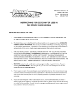
The 9627 is packaged in a conveniently-sized
enclosure with Amphenol connectors. The en-
closure has four mounting holes to permit it to
be fastened to the face of a travel carriage or to a
control podium. The front panel is a membrane
overlay with a backlit LCD display and switches
to control the setup and operation of the unit.
The 9627 control has been designed to be easy
to use. Its operation is made easier by the use of
the display which guides you through the setup
process and, during the welding sequence, tells
you what is happening.
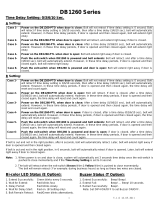
The display has two lines of text, the upper line
is the primary one. This is the line that is used
to set the value of the parameter you are setting.
This is done by calling up the line for the param-
eter required and then turning the adjust knob to
increase or decrease the value. The second line
is used to display status messages (information)
about the progress of the weld sequence to let
you know what stage the process is in. Most of
these messages are normally only displayed after
the start push-button has been pressed.
TRAV SPEED 10.0ipm
SERIES 9600 CONTROL
POWER STOPSTART
REV FOR
UP
DOWN
EMERGENCY
STOP
ADJUST
UP
TRAV SPEED 10.0ipm
ADJUST
DOWN

9627 Microprocessor Controller
- 14 -
POWER
UP
DOWN
ADJUST
REV
FOR
The push-button power switch is used
to provide primary power to the 9627
control. The rst press of the switch
turns on the control. The screen will
become active and display the start-up message.
A second press of this push-button switches the
control off.
These two touch pads are used to scroll
the display up and down. The down
touch pad scrolls down the display
- this takes you through the various
control options in a logical order. The up touch
pad is used to go back through the lines of the
display options. In the standard operating mode
of the 9627 control, these touch pads have no
other purpose.
The adjustment knob is used to change
the value which is currently displayed.
You will note that the knob “incre-
ments”, each incremental movement
of the knob increases the value by its smallest
increment. If the knob is rotated quickly, you
will see that the numbers increase or decrease
faster. The knob can be used to preset the speed
before the motor starts or to change the speed
when the motor is running.
These two touch pads are used to
jog the travel in a reverse or for-
ward direction. When the touch
pad is pressed, travel will begin in the direction
selected and will continue as long as the pad is
pressed. When the touch pad is released, travel
will stop. In addition to the jog facility provided
by the touch pads, they are capable of providing
two more functions.
Rapid Jog: This is achieved by pressing the
forward or reverse touch pad for a short time,
releasing it and then quickly pressing it again.
Travel will start and, after a short time, will
speed up to the “rapid” speed. Rapid travel will
continue until the touch pad is released.
Maintained Jog: This is achieved by first
pressing the forward or reverse touch pad and,
while still pressing this touch pad, pressing
and releasing the start button. The forward or
reverse switch can then be released. The travel
will rotate at rapid speed until it is stopped by
pressing the stop button. This feature is useful
for moving the carriage through a considerable
distance to a desired position.
Depressing and releasing the start
push-button will start the weld se-
quence which will continue until
the stop or emergency stop button is
pressed. Pressing the start push-button while
the forward or reverse touch pad is pressed will
initiate maintained, rapid speed linear travel.
Depressing and releasing the stop
push-button will stop the weld se-
quence.
The emergency stop push-button is a
large, red mushroom-headed switch
designed to stop all operations quickly
in the event of an emergency. When
pressed, the travel will be immediately stopped
and power will be removed from the motor. To
reactivate the system, the switch must be reset
by being pulled out. After reactivation, travel
must be restarted in the normal way using the
start button.
START
STOP
EMERGENCY
STOP
Section V.
Controls

9627 Microprocessor Controller
- 15 -
Section VI.
Modes of Operation
A. Operator Mode
This is the mode which is used by the operator
to run the longitudinal carriage. The system is
automatically set to this mode when the control
is switched on.
To set the conditions for operation, the operator
can scroll through the various screens and make
the appropriate changes. These changes will be
displayed on the top line of the display.
As the system is operating, various informa-
tion messages appear on the lower line of the
display.
Display Screens - Upper Line
Screen 1 WELCOME SCREEN
This screen appears automatically when the unit
is switched on and remains on the screen for ap-
proximately 3 seconds. It identies the model
of the control.
The next screen will appear automatically.
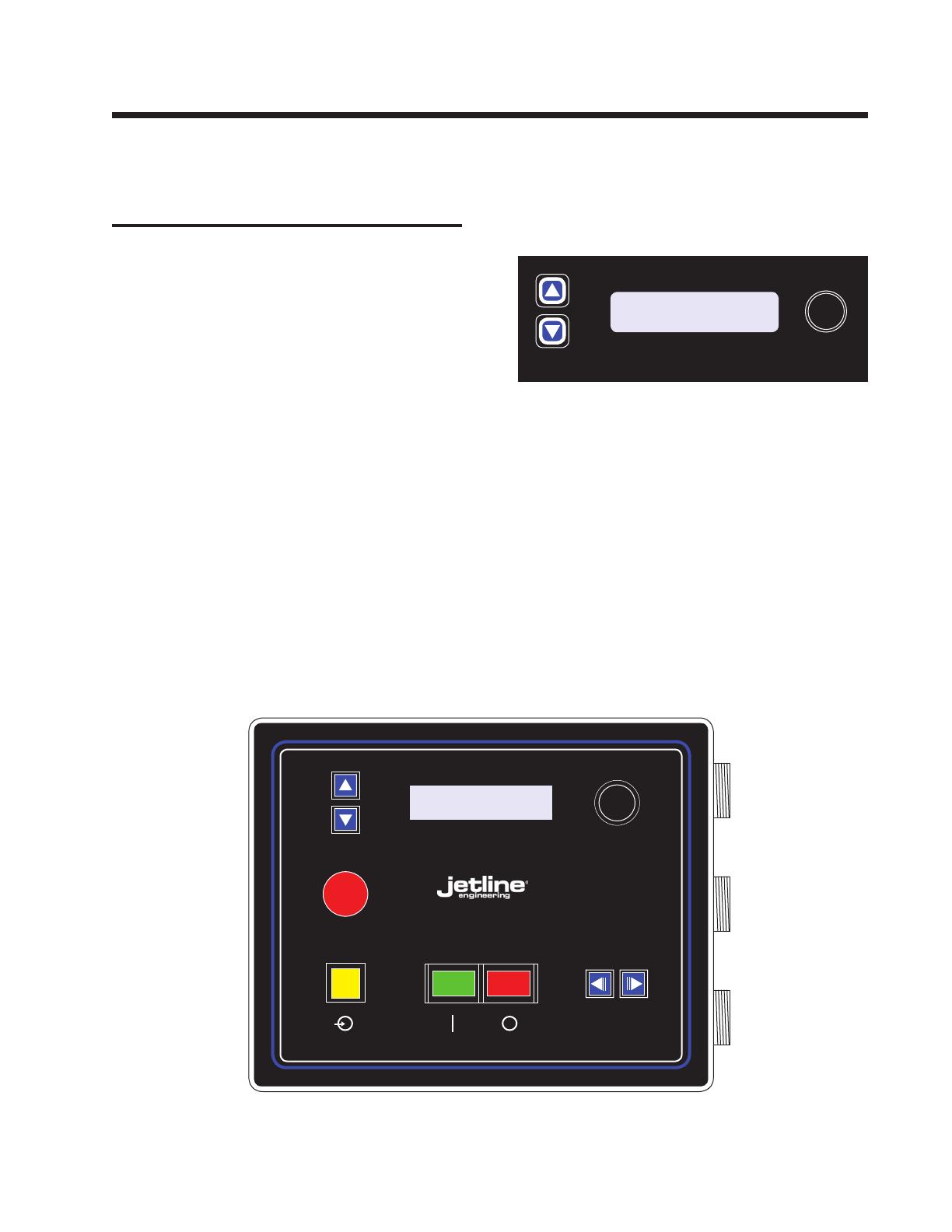
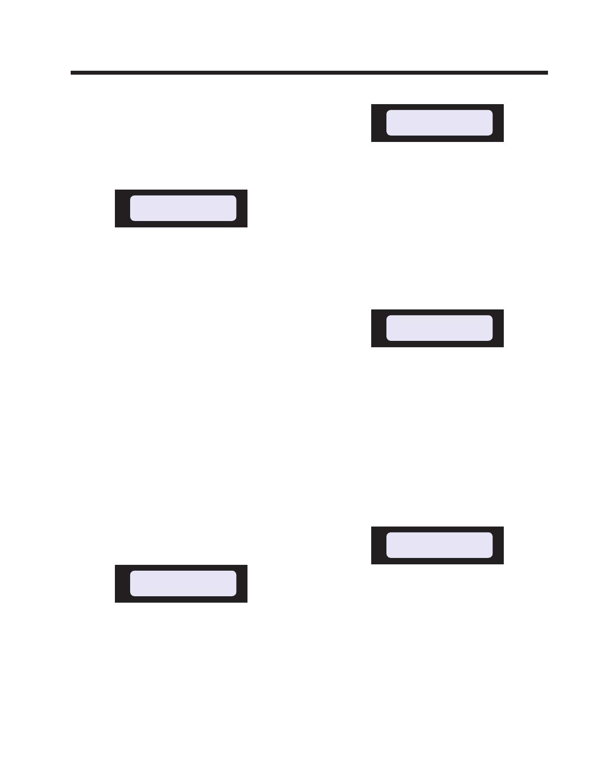
Screen 2 TRAVEL SPEED
When the second screen appears, it displays
the current level of travel speed. If this speed
is correct, the start button can be pressed to im-
mediately initiate the weld sequence. If a start
delay has been programmed, travel will start
after the start delay time has elapsed.
Jetline Engineering
Model 9627
TRAV SPEED 10.0ipm
Speed will be displayed in IPM (inches per min-
ute) or CPM (centimeters per minute). Selection
of IPM or CPM is made in the calibration mode
(see Screen 35).
If it is desired to change the speed, this is done
by turning the adjust knob to increase or de-
crease the speed as necessary. As the change
is made, the number on the display changes
accordingly.
The travel speed can be adjusted from the mini-
mum to maximum value which has been set in
the calibration mode (see Screens 26 and 29).
Press the scroll down arrow to proceed to the
next screen.
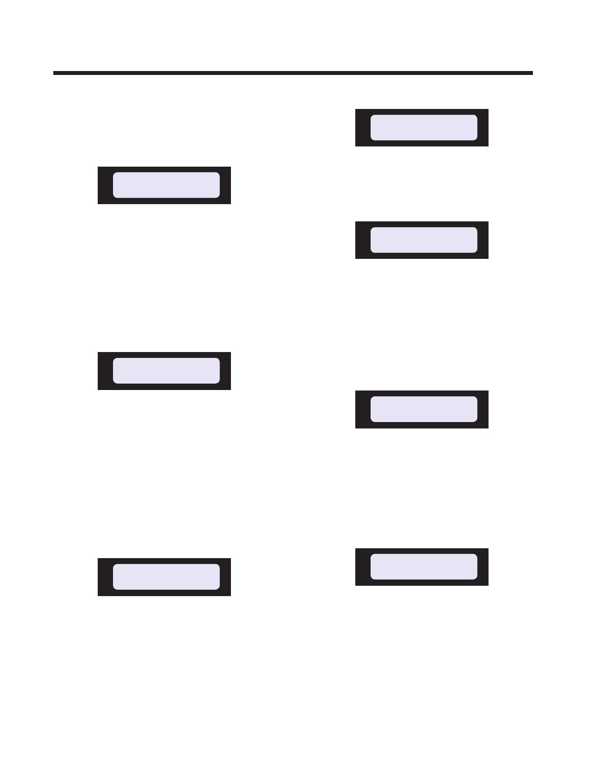
Screen 3 TORCH LIFT
This screen permits you to manually operate
the torch lift. When the screen reads Out, the
torch lift will be in a retracted position prior to
the start of the weld sequence. The pneumatic
torch lift can be lowered by turning the adjust
knob to In. No other screen can be selected
until the adjust knob is turned to place the torch
in the Out position.
Press the scroll down arrow to proceed to the
next screen.
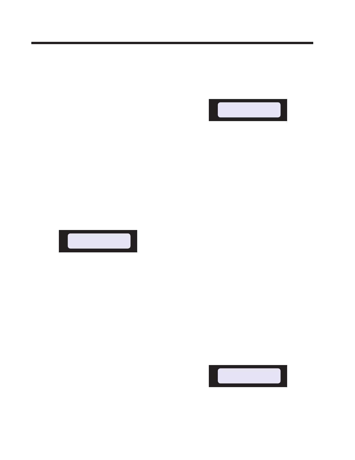
Screen 4 START DELAY
This screen allows a start delay to be set by
turning the adjust knob to increase or decrease
its value. As the change is made, the number
on the display changes accordingly.
The start delay initiates when the “Arc On” sig-
nal has been received from the welding power
supply. If arc wait mode is Off, the start delay
START DELAY 2.8sec
TORCH LIFT Out
9627 Microprocessor Controller
- 16 -
initiates when the contactor signal is given to
the welding power supply (at the end of PTL
start delay time).
The start delay is used to start travel at the cor-
rect time in the weld start up sequence. If the
9627 controlled carriage is part of a system and
a power supply with current upslope is being
used, it is recommended to initiate travel when
the current has sloped up to about 50% of its
weld value. This will ensure that the weld pool
is correctly established before travel starts. If
the total time for initial current and upslope is
set to 2 seconds on the welding power supply,
a travel start delay of approximately 1 second
would be appropriate.
The start delay can be set from 0 to 99.9 sec-
onds.
Press the scroll down arrow to proceed to the
next screen.
Screen 5 STOP DELAY
This screen allows a stop delay to be set by turn-
ing the adjust knob to increase or decrease its
value. As the change is made, the number on
the display changes accordingly.
When the stop push-button is pressed (or when a
remote stop signal is received), travel will con-
tinue until the stop delay has timed out. After the
stop delay has elapsed, the carriage will stop.
The stop delay time can be set from 0 to 99.9
seconds.
The stop delay is used to stop the travel at the
correct time in the weld sequence. If the 9627
controlled carriage is part of a system and a
power supply with current downslope is be-
ing used, it is recommended to stop the travel
when the current has sloped down to the nal
current level. If, for example, the total time
for downslope is set to 10 seconds, a travel stop
delay of 10 seconds would be appropriate. This
will produce an acceptable weld taper and avoid
a crater crack in the end of the weld.
Press the scroll down arrow to proceed to the
next screen.
Screen 6 WELD TIMER
This screen allows the weld timer to be activated
or deactivated by turning the adjust knob to
select On or Off.
If the weld timer is set to On, the weld length
will be controlled by time. The weld time will
commence at the same time as the start delay
time. At the end of the weld time, the stop delay
will be initiated and a signal will be sent to the
power supply (if one is interconnected) to initiate
the downslope and nal weld sequence.
If the weld timer is set to Off, the weld length
will be controlled manually by pressing the stop
push-button, this will initiate the downslope and
stop delay time (if one has been programmed).
An alternative method of controlling the length
of the weld is by an external signal. The longitu-
dinal carriage and track could be tted with limit
switches. If this is the case, the switches can be
used to dene an end of travel position and can
be used to send a signal to the 9627 control to
initiate the stop sequence. An encoder controller
could also be interconnected.
Press the scroll down arrow to proceed to the
next screen.
If the weld timer has been set to On, the fol-
lowing screen will appear.
Screen 7 WELD TIME
This screen allows the length of the weld time to
be set by turning the adjust knob to increase or
decrease its value. As the change is made, the
STOP DELAY 3.9sec
WELD TIMER On
WELD TIME 86.5sec
9627 Microprocessor Controller
- 17 -
number on the display changes accordingly.
The weld time can be set from 0 to 999.9 sec-
onds.
Press the scroll down arrow to proceed to the
next screen.
Screen 8 TRAVEL SPEED (Locked)
This is the nal control screen and it is similar to
screen 2. However, with this screen displayed,
it is impossible to change to the travel speed
setting. This screen has been created so that any
accidental movement of the adjust knob cannot
inadvertently affect the travel speed setting.
To change the travel speed, press the scroll up
or down arrow to proceed to screen 2.
Display Screens - Lower Line
The second line of the display is reserved for
messages that inform the status of the system.
These messages fall into one of three catego-
ries:
• Messages that appear prior to welding.
• Messages that can appear at any time.
• Messages that appear during a weld se-
quence.
PRE-WELD MESSAGES
Speed Adjustment Locked
This message is displayed when the operation of
the adjust knob is locked out. When this mes-
sage is displayed, the adjust knob has no effect
and the travel speed cannot be altered.
High Limit
This message will be displayed whenever the
adjust knob is turned clockwise and the upper
limit of the parameter being adjusted has been
reached. The message remains on the screen
until the value is reduced below the limit.
This message also appears during welding if the
upper limit of speed is reached, in this case, the
message appears only as long as the adjust knob
is being turned clockwise.
Low Limit
This message is displayed whenever the adjust
knob is turned counterclockwise and the lower
limit of the parameter being adjusted has been
reached. The message will remain displayed on
the screen until the value of the parameter is
increased above the limit.
This message also appears during welding if the
lower limit of speed is reached, in this case, the
message appears only as long as the adjust knob
is being turned counterclockwise.
Jog forward
Whenever the forward jog touch pad is pressed,
the screen will display the message shown above.
Travel will proceed in a forward direction at the
pre-programmed forward jog speed setting (this
speed is set in the setup mode of operation of
the 9627 control - see Screen 9).
TRAV SPEED 135.0ipm
Cannot go any higher
TRAV SPEED 3.0ipm
Cannot go any lower
TRAV SPEED 10.0ipm
Adjustment Locked
TRAV SPEED 40.5ipm
Jog Forward
TRAV SPEED 10.0ipm
Adjustment Locked

9627 Microprocessor Controller
- 18 -
Travel will continue as long as the touch pad
is pressed. The message will remain on the
screen for as long as the travel is being jogged
forward.
Jog reverse
Whenever the reverse jog touch pad is pressed,
the screen will display the message shown
above. Travel will proceed in a reverse direction
at the pre-programmed reverse jog speed setting
(this speed is set in the setup mode of operation
of the 9627 control - see Screen 10).
Travel will continue as long as the touch pad
is pressed. The message will remain on the
screen for as long as the travel is being jogged
in reverse.
Rapid jog forward
When the forward jog touch pad is pressed, then
released and then quickly pressed again, after a
short period of time, travel will speed up to the
pre-programmed rapid forward jog speed (this
speed is set in the setup mode of operation of
the 9627 control - see Screen 11).
Travel will continue at rapid speed as long as the
touch pad is pressed. The message will remain
on the screen as long as the carriage is traveling
at this speed.
Rapid jog reverse
When the reverse jog touch pad is pressed, then
released and then quickly pressed again, after a
short period of time, travel will speed up to the
pre-programmed rapid reverse jog speed (this
speed is set in the setup mode of operation of
the 9627 control - see Screen 11).
Travel will continue at rapid speed as long as the
touch pad is pressed. The message will remain
on the screen as long as the carriage is traveling
at this speed.
Maintained forward
When the forward jog touch pad is pressed and
held until the start button is pressed and released,
the carriage will travel forward at maximum
speed and will continue to do so until the stop
button is pressed.
This message remains on the screen as long as
the carriage is traveling forward at maximum
speed.
Maintained reverse
When the reverse jog touch pad is pressed and
held until the start button is pressed and released,
the carriage will travel in reverse at maximum
speed and will continue to do so until the stop
button is pressed.
The message will remain on the screen as long
as the carriage is reversing at maximum speed.
Jogging disabled
This message is displayed when a jog touch pad
is pressed while the system is in any program-
ming screen.
When the control is being set up (start or stop
delays are being set), or whenever the system is
in setup or calibration mode, travel is disabled.
TRAV SPEED 108.0ipm
Jog Reverse Rapid
TRAV SPEED 135.0ipm
Maintained Reverse
TRAV SPEED 135.0ipm
Maintained Forward
TRAV SPEED 94.5ipm
Jog Forward Rapid
TRAV SPEED 67.5ipm
Jog Reverse
STOP DELAY 3.9sec
Jogging Disabled

9627 Microprocessor Controller
- 19 -
Jogging is only possible when the control is
displaying the travel speed screen (Screens 2
or 8).
ANYTIME MESSAGES
Emergency stop
If the emergency stop button is pressed, the
above message will be displayed. This can oc-
cur at any time and the message will remain on
the screen until after the emergency stop button
is reset by pulling out the knob.
DURING WELD MESSAGES
PTL start delay
This message will be displayed after the start
button has been pressed (or a remote start signal
has been received) and during the time that the
PTL start delay is timing out. Time counts down
from the pre-programmed value to zero.
This message will only be displayed if the auto-
matic torch lift facility is set to On in the set-up
mode (see Screen 16)
Waiting for arc on
At the end of the PTL start delay time, the 9627
sends a signal to the welding power supply to
initiate the arc. If the arc wait mode (Screen
12) has been set to On, this screen will be dis-
played until the control has received a signal
from the power supply indicating that the arc
has been correctly established. This avoids the
weld sequence starting before the arc is fully
established.
Start delay
The travel start delay will be initiated and the
above message will be displayed as follows:
When the start signal (local or remote) is given
(if Auto torch lift is Off or PTL start delay time
is 0)
At the end of the PTL start delay time (if arc wait
mode is Off and Auto torch lift is On)
After the arc has been established (if arc wait
mode is set to On)
Time counts down from the pre-programmed
value (as set in Screen 4) to zero. At the end
of this time, the carriage starts traveling at the
pre-programmed travel speed.
Sensing delay
After any of the above delays have timed out,
and following the initiation of the travel, this
message will be displayed (providing that
Closed Loop Mode is On, Screen 22).
The message will continue to be displayed dur-
ing the time that the closed loop sensing delay
is timing out. Time counts down from the
pre-programmed value (as set in Screen 24) to
zero. During this time, the travel speed runs in
open loop.
Weld Time
If the Weld Timer is set to On (screen 6) and
after the arc has been established, the weld time
is started. The weld time is displayed and counts
down from the pre-programmed value (as set in
Screen 7) to zero.
TRAV SPEED 10.0ipm
PTL Start Delay 3.6sec
TRAV SPEED 10.0ipm
Start Delay 2.6sec
TRAV SPEED 10.0ipm
Waiting for arc on
TRAV SPEED 10.0ipm
Sensing Delay 0.8sec
TRAV SPEED 10.0ipm
Weld Time 142.3sec
TRAV SPEED 0.0ipm
Emergency Stop On
9627 Microprocessor Controller
- 20 -
If the Weld Timer is set to Off (screen 6), the
weld time will be displayed when the arc is
initiated and will count up to indicate the weld
elapsed time.
Stop delay
The above message will be displayed after the
stop push-button is pressed, the weld timer has
timed out or a remote stop signal has been given
to the 9627 control. Time counts down from
the pre-programmed value to zero. During this
time the travel continues at the pre-programmed
travel speed. At the end of the stop delay time,
the carriage stops.
PTL stop delay
This message will be displayed after the travel
has stopped and during the time that the PTL stop
delay is timing out. Time counts down from the
pre-programmed value to zero.
This message appears when the welding system
is tted with a solenoid-operated pneumatic
torch lift and Screen 16 is switched to On.
The torch lift moves the torch away from the
part to provide clearance for unloading.
Home delay
This message will be displayed after the PTL
stop delay time has elapsed, or if there is no PTL
stop delay, at the end of the stop delay time.
Time counts down from the pre-programmed
value to zero.
At the end of the Home Delay time, the carriage
will travel at maximum speed in reverse until the
home limit switch is encountered.
Returning Home
This message will be displayed whenever the
carriage is traveling back to the home position
at the end of the weld.
At Forward Limit
This message will be displayed whenever
the forward jog touch pad is pressed and the
carriage is at the forward limit. Under these
circumstances, jogging in this direction is not
possible. It will be necessary to jog the carriage
in the reverse direction to move away from the
limit switch.
At Reverse Limit
This message will be displayed whenever the
reverse jog touch pad is pressed and the carriage
is at the home limit. Under these circumstances,
jogging in this direction is not possible. It will
be necessary to jog the carriage in the forward
direction to move away from the limit switch.
Reset to Proceed
This message will be displayed whenever the
manual torch lift (Screen 3) is selected to the In
position. This will cause the torch lift (if tted)
to operate to bring the torch into the weld posi-
tion. This facility is provided to permit the torch
to workpiece relationship to be checked before
the weld sequence is started. In this condition,
the scroll touch pads are deactivated.
TRAV SPEED 10.0ipm
Home Delay 1.4sec
TRAV SPEED 135.0ipm
Returning Home
TRAV SPEED 10.0ipm
At Forward Limit
TRAV SPEED 10.0ipm
At Reverse Limit
TRAV SPEED 10.0ipm
PTL Stop Delay 2.9sec
TORCH LIFT In
Reset to Proceed
TRAV SPEED 10.0ipm
Stop Delay 5.7sec
/