Page is loading ...

310AAV/JAV
Induced-Combustion
4-Way Multipoise Furnace
Installation, Start-up, Operating, and
Service and Maintenance Instructions
-Series A
The 310AAV/JAV 4-Way Multipoise Gas Furnace was designed by Bryant
dealers for Bryant dealers. Applications are easy with 4-way multipoise
design, through-the-furnace downflow venting, 13 different venting options,
and a door designed for easy service access. An inner blower door is
provided for tighter sealing in sensitive applications. The 310AAV/JAV
furnace is approved for use with natural or propane gas, and the 310JAV is
also approved for use in Low NOx Air Quality Management Districts.
STANDARD FEATURES
• Noise elimination combustion system
• Microprocessor based control center
Adjustable heating air temperature rise
LED diagnostics and self test feature
• Patented blocked vent safeguard to ensure proper furnace venting
• All models are Chimney Friendly when used with accessory vent kit
• Four-position furnace: upflow, horizontal right, horizontal left,
downflow
Thirteen different vent options
• Heat pump compatible
• Hot surface ignition (HSI)
• Residential installations eligible for consumer financing through the Comfort
Credit Program
• Twinning in Upflow, Downflow and Horizontal
LIMITED WARRANTY
• 20-year warranty on “Super S™” heat exchanger
• 5-year parts warranty on all other components
Catalog No: 5331-205 Form No. II 310A-45-3 12-02

Single-Stage
Induced-Combustion
4-Way Multipoise Furnace
Installation, Start-up, Operating, and
Service and Maintenance Instructions
Series 100/A
NOTE: Read the entire instruction manual before starting the
installation.
This symbol → indicates a change since the last issue.
TABLE OF CONTENTS
SAFETY CONSIDERATIONS.....................................................2
INTRODUCTION..........................................................................4
CODES AND STANDARDS........................................................4
Safety.........................................................................................4
General Installation...................................................................4
Combustion and Ventilation Air ..............................................4
Duct Systems ............................................................................5
Acoustical Lining and Fibrous Glass Duct..............................5
Gas Piping and Gas Pipe Pressure Testing..............................5
Electrical Connections ..............................................................5
ELECTROSTATIC DISCHARGE (ESD) PRECAUTIONS
PROCEDURE ................................................................................5
LOCATION....................................................................................5
General......................................................................................5
Location Relative to Cooling Equipment ................................6
AIR FOR COMBUSTION AND VENTILATION......................6
Unconfined Space.....................................................................7
Confined Space.........................................................................7
INSTALLATION...........................................................................8
Upflow Installation ...................................................................8
Bottom Return Air Inlet......................................................8
Side Return Air Inlet...........................................................8
Leveling Legs (If Desired)..................................................8
Downflow Installation ..............................................................8
Bottom Return Air Inlet......................................................9
Horizontal Installation ..............................................................9
Suspended Unit Support......................................................9
Platform Unit Support.........................................................9
Roll-Out Protection..............................................................9
Bottom Return Air Inlet......................................................9
Side Return Air Inlet...........................................................9
Filter Arrangement....................................................................9
Air Ducts...................................................................................9
General Requirements .........................................................9
Ductwork Acoustical Treatment .......................................11
Supply Air Connections....................................................12
Return Air Connections.....................................................13
Gas Piping...............................................................................13
Electrical Connections ............................................................15
115-V Wiring.....................................................................16
J-Box Relocation ...............................................................16
Electrical Connection to J-Box.........................................16
For Power Cord Installation..............................................16
For BX Cable Installation.................................................17
For Power Cord Installation..............................................17
24-V Wiring.......................................................................17
Accessories ........................................................................17
Venting....................................................................................18
General Venting Requirements.........................................19
Masonry Chimney Requirements......................................19
Appliance Application Requirements ...............................21
Additional Venting Requirements.....................................21
Sidewall Venting ...............................................................21
START-UP, ADJUSTMENT, AND SAFETY CHECK............21
General....................................................................................21
Start-Up Procedures................................................................23
Adjustments.............................................................................23
Check Safety Controls............................................................29
Checklist..................................................................................30
SERVICE AND MAINTENANCE PROCEDURES..................30
Introduction.............................................................................30
General...............................................................................30
Electrical Controls and Wiring .........................................30
Care and Maintenance............................................................31
Cleaning and/or Replacing Air Filter ...............................32
Blower Motor and Wheel..................................................32
Cleaning Heat Exchanger..................................................33
Sequence of Operation............................................................34
Wiring Diagrams.....................................................................35
Troubleshooting ......................................................................35
REGISTERED QUALITY SYSTEM
C
a
r
r
i
e
r
C
o
r
p
o
r
a
t
i
o
n
R
E
G
I
S
T
E
R
E
D
F
I
R
M
I
S
O
9
0
0
1
#
A
2
8
8
3
®
EFFICIENCY
RATING
CERTIFIED
CERTIFIED
Cancels: II 310A-45-2/IM-PG8J-02 II 310A-
45-3 / IM-PG8J-03
Manufacturer reserves the right to discontinue, or change at any time, specifications or designs without notice and without incurring obligations.
Book 1 4
Tab 6a 8a
PC 101 Catalog No. See Cover Printed in U.S.A. Form 58ST-11SI Pg 1 12-02 Replaces: 58ST-2SI

SAFETY CONSIDERATIONS
Improper installation, adjustment, alteration, service, mainte-
nance, or use can cause carbon monoxide poisoning, explo-
sion, fire, electrical shock, or other conditions which may
cause personal injury or property damage. Consult a qualified
installer, service agency, local gas supplier, or your distribu-
tor or branch for information or assistance. The qualified
installer or agency must use only factory-authorized and
listed kits or accessories when modifying this product. Failure
to follow this warning could result in electrical shock, fire,
personal injury, or death.
Application of this furnace should be indoors with special
attention given to vent sizing and material, gas input rate, air
temperature rise, unit leveling, and unit sizing. Improper
installation or misapplication of furnace can require excessive
servicing or cause premature component failure.
Installing and servicing heating equipment can be hazardous due to
gas and electrical components. Only trained and qualified
personnel should install, repair, or service heating equipment.
Untrained personnel can perform basic maintenance functions
such as cleaning and replacing air filters. All other operations must
be performed by trained service personnel. When working on
heating equipment, observe precautions in literature, on tags, and
on labels attached to or shipped with unit and other safety
precautions that may apply.
These instructions cover minimum requirements and conform to
existing national standards and safety codes. In some instances,
these instructions exceed certain local codes and ordinances,
especially those that may not have kept up with changing residen-
tial construction practices. We require these instructions as a
minimum for a safe installation.
Sheet metal parts may have sharp edges or burrs. Use care and
wear appropriate protective clothing and gloves when han-
dling parts. Failure to follow this caution could result in
personal injury.
Wear safety glasses and work gloves. Have fire extinguisher
available during start-up and adjustment procedures and service
calls.
This is the safety-alert symbol
. When you see this symbol on
the furnace and in instructions or manuals, be alert to the potential
for personal injury.
Understand the signal words DANGER, WARNING, CAUTION,
and NOTE. These words are used with the safety-alert symbol.
DANGER identifies the most serious hazards which will result in
severe personal injury or death. WARNING signifies a hazard
which could result in personal injury or death. CAUTION is used
to identify unsafe practices which would result in minor personal
injury or product and property damage. NOTE is used to highlight
suggestions which will result in enhanced installation, reliability,
or operation.
1. Use only with type of gas approved for this furnace. Refer to
the furnace rating plate.
2. Install this furnace only in a location and position as specified
in the “Location” section of these instructions.
3. Provide adequate combustion and ventilation air to the furnace
space as specified in “Air for Combustion and Ventilation”
section.
4. Combustion products must be discharged outdoors. Connect
this furnace to an approved vent system only, as specified in
the “Venting” section of these instructions.
5. Never test for gas leaks with an open flame. Use a commer-
cially available soap solution made specifically for the detec-
tion of leaks to check all connections, as specified in the “Gas
Piping” section.
NOTES:
1. Two additional 7/8-in. diameter holes are located in the top plate.
2. Minimum return-air openings ar furnace, based on metal duct. If flex duct is used, see flex duct manufacturer’s recommendations for equivalent diameters.
a. For 800 CFM-16-in. round or 14 1/2 x 12-in. rectangle.
b. For 1200 CFM-20-in. round or 14 1/2 x 19 1/2-in. rectangle.
c. For 1600 CFM-22-in. round or 14 1/2 x 22-in. rectangle.
d. For airflow requirements above 1800 CFM, see Air Delivery table in Product Data literature for specific
use of single side inlets. The use of both side inlets, a combination of 1 side and the bottom, or the
bottom only will ensure adequate return air openings for airflow requirements above 1800 CFM.
→ Fig. 1—Dimensional Drawing
A02304
28-7/8"
25-1/4"
22-9/16"
JUNCTION BOX
LOCATION
7/8" DIA
ACCESSORY
1/2" DIA THERMOSTAT
WIRE ENTRY
3-15/16"
LEFT HAND GAS
ENTRY
33-5/16"
24-7/8"
5-1/2"
7/8" DIA. ACCESSORY
11/16"
21-5/8"
BOTTOM INLET
1-11/16"
13/16"
11/16"
1-9/16"
2-9/16"
4-13/16"
AIRFLOW
19"
OUTLET
13/16"
11/16"
8-7/16"
1-7/16"
ALTERNATE
JUNCTION BOX
LOCATION (TYP)
VENT OUTLET
5 PLACES (TYP)
3-3/4"
1-1/2" DIA.
RIGHT HAND
GAS ENTRY
1/2" DIA. THERMOSTAT
WIRE ENTRY
SIDE INLET
14-7/8"
7/8" DIA. ACCESSORY
1-1/4"
1"
22-1/16"
A
D
F
E
2
→
→

6. Always install furnace to operate within the furnace’s intended
temperature-rise range with a duct system which has an
external static pressure within the allowable range, as speci-
fied in the “Start-Up, Adjustments, and Safety Check” section.
See furnace rating plate.
7. When a furnace is installed so that supply ducts carry air
circulated by the furnace to areas outside the space containing
the furnace, the return air shall also be handled by duct(s)
sealed to the furnace casing and terminating outside the space
containing the furnace. See “Air Ducts” section.
8. A gas-fired furnace for installation in a residential garage must
be installed as specified in the warning box in the “Location”
section.
9. The furnace is not to be used for temporary heating of
buildings or structures under construction.
10. These Multipoise Gas-Fired Furnaces are CSA (A.G.A. and
C.G.A.) design-certified for natural and propane gases (see
furnace rating plate) and for installation in alcoves, attics,
basements, closets, utility rooms, crawlspaces, and garages.
The furnace is factory-shipped for use with natural gas. A
→ Fig. 2—Clearances to Combustibles
A02330
MINIMUM INCHES CLEARANCE TO COMBUSTIBLE CONSTRUCTION
Cette fournaise à air pulsé est équipée
pour utilisation avec gaz naturel et altitudes
comprises entre 0-3,050m (0-10,000 pi).
Utiliser une trousse de conversion, fournie par
le fabricant, pour passer au gaz propane ou pour
certaines installations au gaz naturel.
Cette fournaise est prévue pour être
installée dans un bâtiment construit sur place.
Cette fournaise peut être installée sur
un plancher combustible dans une alcôve ou
dans un garde-robe en respectant le minimum
d'espace libre des matériaux combustibles, tel
qu'indiqué sur le diagramme..
Cette fournaise peut être utilisée avec un
conduit d´évacuation de Type B-1 ou connectée
au conduit commun d´autres appareils à gaz..
DISTANCE MINIMALE EN POUCES AUX CONSTRUCTIONS COMBUSTIBLES
INSTALLATION
327590-101 REV. B
MINIMUM INCHES CLEARANCE TO COMBUSTIBLE CONSTRUCTION
DÉGAGEMENT MINIMUM EN POUCES AVEC ÉLÉMENTS
DE CONSTRUCTION COMBUSTIBLES
Ø
*
Installation on non-combustible floors only.
For Installation on combustible flooring only when installed on special base, Part No. KGASB0201ALL,
Coil Assembly, Part No. CD5 or CK5, or Coil Casing, Part No. KCAKC.
18 inches front clearance required for alcove.
Indicates supply or return sides when furnace is in the horizontal position. Line contact only permissible
between lines formed by intersections of the Top and two Sides of the furnace jacket, and building joists,
studs or framing.
Clearance in inches
Dégagement (po).
Clearance arrows
do not change with
furnace orientation.
Les fléches de dégagement
ne changent pas avec
l´orientation de la fournaise.
BOTTOM
DESSOUS
0
"
3"
0"
0"
1"
0"
30"
MIN
S
I
D
E
C
Ô
T
É
F
R
O
N
T
A
V
A
N
T
B
C
K
A
R
R
I
È
A
E
R
S
E
R
V
I
E
C
E
N
T
R
T
E
N
E
I
V
A
N
A
T
F
R
O
N
T
S
I
E
C
Ô
T
È
F
O
U
U
F
R
N
A
C
S
E
E
I
A
R
N
Ø
Vent Clearance to combustibles:
For Single Wall vents 6 inches (6 po).
For Type B-1 vent type 1 inch (1 po).
Dégagement de l´évent avec combustibles:
Pour conduit d´évacuation à paroi simple 6 po (6 inches).
Pour conduit d´évacuation de Type B-1 1 po (1 inch).
TOP / PLENUM
DESSUS / CHAMBRED’AIR
D
*
*
Cette fournaise est approuvée pour l´installation HORIZONTALE
et la circulation d´air VERS LE HAUT et VERS LE BAS.
†
†
This furnace is approved for UPFLOW, DOWNFLOW, and
HORIZONTAL installations.
MIN
Ø
*
†
Pour l´installation sur plancher non combustible seulement.
Pour l´installation sur un plancher combustible seulement quand on utilise la base spéciale, pièce
n KGASB0201ALL, l´ensemble serpentin, pièce n CD5 ou CK5, ou le carter de serpentin, pièce
n KCAKC.
Dans une alcôve, on doit maintenir un dégagement à l´avant de 18 po (450 mm).
La position indiquée concerne le côté d´entrée ou de retour quand la fournaise est dans la
position horizontale.
Le contact n´est permis qu´entre les lignes formées par les intersections du dessus et des
deux côtés de la chemise de la fournaise et les solives, montant sous cadre de charpente.
POUR LA POSITION COURANT DESCENDANT:
DOWNFLOW POSITIONS:
This forced air furnace is equipped for use with
natural gas at altitudes 0-10,000 ft (0-3,050m).
An accessory kit, supplied by the
manufacturer,shall be used to convert to propane
gas use or may be required for some natural gas
applications.
This furnace is for indoor installation in a
building constructed on site.
This furnace may be installed on combustible
flooring in alcove or closet at minimum clearance
as indicated by the diagram from combustible
material .
This furnace may be used with a Type B-1 Vent
and may be vented in common with other gas-
fired appliances.
o
o
o
3
→

CSA (A.G.A. and C.G.A.) listed gas conversion kit is required
to convert furnace for use with propane gas.
11. See Fig. 2 for required clearances to combustibles.
12. Maintain a 1-in. clearance from combustible materials to
supply air ductwork for a distance of 36 inches horizontally
from the furnace. See NFPA 90B or local code for further
requirements.
13. These furnaces SHALL NOT be installed directly on carpet-
ing, tile, or any other combustible material other than wood
flooring. In downflow installations, factory accessory floor
base MUST be used when installed on combustible materials
and wood flooring. Special base is not required when this
furnace is installed on manufacturer’s Coil Assembly Part No.
CD5 or CK5, or when Coil Box Part No. KCAKC is used.
INTRODUCTION
This 4–way multipoise Category I fan-assisted furnace is CSA
(A.G.A. and C.G.A.) design-certified for natural and propane gas
and for installation in alcoves, attics, basements, closets, utility
rooms, crawlspaces, and garages. A fan-assisted furnace is an
appliance equipped with an integral mechanical means to either
draw or force products of combustion through the combustion
chamber and/or heat exchanger. The furnace is factory-shipped for
use with natural gas. A CSA (A.G.A. and C.G.A.) listed gas
conversion kit is required to convert furnace for use with propane
gas. This furnace is not approved for installation in mobile homes,
recreational vehicles, or outdoors.
This furnace is designed for minimum continuous return-air
temperature of 60°F db or intermittent operation down to 55°Fdb
such as when used with a night setback thermostat. Return-air
temperature must not exceed 85°F db. Failure to follow these
return-air limits may affect reliability of heat exchangers, motors,
and controls. (See Fig. 3.)
For accessory installation details, refer to the applicable instruction
literature.
NOTE: Remove all shipping brackets and materials before oper-
ating the furnace.
CODES AND STANDARDS
Follow all national and local codes and standards in addition to
these instructions. The installation must comply with regulations
of the serving gas supplier, local building, heating, plumbing, and
other codes. In absence of local codes, the installation must
comply with the national codes listed below and all authorities
having jurisdiction.
In the United States and Canada, follow all codes and standards for
the following:
Step 1—Safety
• US: National Fuel Gas Code (NFGC) NFPA 54–2002/ANSI
Z223.1–2002 and the Installation Standards, Warm Air Heating
and Air Conditioning Systems ANSI/NFPA 90B
• CANADA: CAN/CGA-B149.1–and .2–M00 National Standard
of Canada. Natural Gas and Propane Installation Codes (NSC-
NGPIC)
Step 2—General Installation
• US: Current edition of the NFGC and the NFPA 90B. For
copies, contact the National Fire Protection Association Inc.,
Batterymarch Park, Quincy, MA 02269; or for only the NFGC,
contact the American Gas Association, 400 N. Capitol, N.W.,
Washington DC 20001 or www.NFPA.org.
• CANADA: NSCNGPIC. For a copy, contact Standard Sales,
CSA International, 178 Rexdale Boulevard, Etobicoke (Tor-
onto), Ontario, M9W 1R3 Canada
Step 3—Combustion and Ventilation Air
• US: Section 5.3 of the NFGC, Air for Combustion and
Ventilation
Table 1—Dimensions (IN.)
UNIT SIZE A B C
VENT
CONN*
SHIP WT. (LB)
045-08/024045 14-3/16 12-9/16 12-11/16 4 104
045-12/036045 14-3/16 12-9/16 12-11/16 4 107
070-08/024070 14-3/16 12-9/16 12-11/16 4 111
070-12/036070 14-3/16 12-9/16 12-11/16 4 115
070-16/048070 17-1/2 15-7/8 16 4 123
090-14/042090 17-1/2 15-7/8 16 4 126
090-16/048090 21 19-3/8 19-1/2 4 139
090-20/060090 21 19-3/8 19-1/2 4 145
110-12/036110 17-1/2 15-7/8 16 4 134
110-16/048110 21 19-3/8 19-1/2 4 145
110-22/066110 21 19-3/8 19-1/2 4 151
135-16/048135 21 19-3/8 19-1/2 4 148
135-22/066135 24-1/2 22-7/8 23 4 163
155-20/060155 24-1/2 22-7/8 23 4 170
*5” or 6” vent connector may be required in some cases.
Fig. 3—Return Air Temperature
A02055
60
4
→
→
→
→

• CANADA: Part 7 of NSCNGPIC, Venting Systems and Air
Supply for Appliances
Step 4—Duct Systems
• US and CANADA: Air Conditioning Contractors Association
(ACCA) Manual D, Sheet Metal and Air Conditioning Con-
tractors National Association (SMACNA), or American Soci-
ety of Heating, Refrigeration, and Air Conditioning Engineers
(ASHRAE) 2001 Fundamentals Handbook Chapter 34.
Step 5—Acoustical Lining and Fibrous Glass Duct
• US and CANADA: current edition of SMACNA and NFPA
90B as tested by UL Standard 181 for Class I Rigid Air Ducts
Step 6—Gas Piping and Gas Pipe Pressure Testing
• US: NFGC; chapters 5, 6, 7, and 12 and National Plumbing
Codes
• CANADA: NSCNGPIC Parts 3, 4, 5, A, B, E and H.
Step 7—Electrical Connections
• US: National Electrical Code (NEC) ANSI/NFPA 70–2002
• CANADA: Canadian Electrical Code CSA C22.1
ELECTROSTATIC DISCHARGE (ESD) PRECAUTIONS
PROCEDURE
Electrostatic discharge can affect electronic components.
Take precautions during furnace installation and servicing to
protect the furnace electronic control. Precautions will pre-
vent electrostatic discharges from personnel and hand tools
which are held during the procedure. These precautions will
help to avoid exposing the control to electrostatic discharge
by putting the furnace, the control, and the person at the same
electrostatic potential.
1. Disconnect all power to the furnace. Multiple disconnects may
be required. DO NOT TOUCH THE CONTROL OR ANY
WIRE CONNECTED TO THE CONTROL PRIOR TO DIS-
CHARGING YOUR BODY’S ELECTROSTATIC CHARGE
TO GROUND.
2. Firmly touch the clean, unpainted, metal surface of the furnace
chassis which is close to the control. Tools held in a person’s
hand during grounding will be satisfactorily discharged.
3. After touching the chassis, you may proceed to service the
control or connecting wires as long as you do nothing to
recharge your body with static electricity (for example; DO
NOT move or shuffle your feet, do not touch ungrounded
objects, etc.).
4. If you touch ungrounded objects (and recharge your body with
static electricity), firmly touch a clean, unpainted metal
surface of the furnace again before touching control or wires.
5. Use this procedure for installed and uninstalled (ungrounded)
furnaces.
6. Before removing a new control from its container, discharge
your body’s electrostatic charge to ground to protect the
control from damage. If the control is to be installed in a
furnace, follow items 1 through 4 before bringing the control
or yourself in contact with the furnace. Put all used and new
controls into containers before touching ungrounded objects.
7. An ESD service kit (available from commercial sources) may
also be used to prevent ESD damage.
LOCATION
Step 1—General
Some assembly and modifications are required when used in any
of the four applications shown in Figure 4.
This furnace must:
• be installed so the electrical components are protected from
water.
• not be installed directly on any combustible material other than
wood flooring. Refer to Introduction section.
• be located close to the chimney/vent and attached to an air
distribution system. Refer to Air Ducts section.
• be provided ample space for servicing and cleaning. Always
comply with minimum fire protection clearances shown on the
furnace clearance to combustible label.
Do not install furnace in a corrosive or contaminated atmo-
sphere. Make sure all combustion and circulating air require-
ments are met, in addition to all local codes and ordinances.
Fig. 4—Multipoise Orientations
A02097
THE BLOWER IS LOCATED
TO THE RIGHT OF THE
BURNER SECTION, AND
AIR CONDITIONED AIR IS
DISCHARGED TO THE LEFT.
THE BLOWER IS
LOCATED BELOW THE
BURNER SECTION, AND
CONDITIONED AIR IS
DISCHARGED UPWARD.
THE BLOWER IS
LOCATED ABOVE THE
BURNER SECTION, AND
CONDITIONED AIR IS
DISCHARGED DOWNWARD
THE BLOWER IS
LOCATED TO THE LEFT
OF THE BURNER SECTION,
AND CONDITIONED AIR IS
DISCHARGED TO THE RIGHT.
5
→
→

This gas furnace may be used for construction heat provided
that:
-The furnace is permanently installed with all electrical
wiring, piping, venting and ducting installed according to
these installation instructions. A return air duct is provided,
sealed to the furnace casing, and terminated outside the space
containing the furnace. This prevents a negative pressure
condition as created by the circulating air blower, causing a
flame rollout and/or drawing combustion products into the
structure.
-The furnace is controlled by a thermostat. It may not be ″hot
wired″ to provide heat continuously to the structure without
thermostatic control.
-Clean outside air is provided for combustion. This is to
minimize the corrosive effects of adhesives, sealers and other
construction materials. It also prevents the entrainment of
drywall dust into combustion air, which can cause fouling and
plugging of furnace components.
-The temperature of the return air to the furnace is no less
than 55 degrees F, with no evening setback or shutdown. The
use of the furnace while the structure is under construction is
deemed to be intermittent operation per our installation
instructions.
-The air temperature rise is within the rated rise range on the
furnace rating plate, and the firing rate has been set to the
nameplate value.
-The filters used to clean the circulating air during the
construction process must be either changed or thoroughly
cleaned prior to occupancy.
-The furnace, ductwork and filters are cleaned as necessary to
remove drywall dust and construction debris from all HVAC
system components after construction is completed.
DO NOT install the furnace on its back or facing down.
Safety control operation will be adversely affected. Never
connect return-air ducts to back of furnace. Failure to follow
this warning could result in fire, personal injury, or death.
(See Fig. 5.)
Step 2—Location Relative to Cooling Equipment
The cooling coil must be installed parallel with, or on the
downstream side of the unit to avoid condensation in the heat
exchangers. When installed parallel with the furnace, dampers or
other flow control must prevent chilled air from entering the
furnace. If the dampers are manually operated, they must be
equipped with means to prevent operation of either unit unless the
damper is in the full-heat or full-cool position.
AIR FOR COMBUSTION AND VENTILATION
Provisions for adequate combustion and ventilation air must be
provided in accordance with Section 5.3 of the NFGC, Air for
Combustion and Ventilation, or applicable provisions of the local
building codes.
Canadian installations must be installed in accordance with NSC-
NGPIC Part 7 and all authorities having jurisdiction.
When the furnace is installed in a residential garage, the
burners and ignition sources must be located at least 18 inches
above the floor. The furnace must be located or protected to
avoid damage by vehicles. When the furnace is installed in a
public garage, airplane hangar, or other building having a
hazardous atmosphere, the furnace must be installed in
accordance with the NFGC or NSCNGPIC. (See Fig. 6.)
Air for combustion must not be contaminated by halogen
compounds, which include fluoride, chloride, bromide, and
iodide. These elements are found in aerosol sprays, deter-
gents, bleaches, cleaning solvents, salts, air fresheners, and
other household products.
All fuel-burning equipment must be supplied with air for fuel
combustion. Sufficient air must be provided to avoid negative
pressure in the equipment room or space. A positive seal must be
made between the furnace cabinet and the return-air duct to
prevent pulling air from the burner area and from blocked vent
safeguard opening.
The operation of exhaust fans, kitchen ventilation fans,
clothes dryers, attic exhaust fans or fireplaces could create a
NEGATIVE PRESSURE CONDITION at the furnace.
Make-up air MUST be provided for the ventilation devices, in
addition to that required by the furnace. Refer to Carbon
Monoxide Hazard warning in venting section of these instruc-
tions to determine amount of make-up air required.
The requirements for combustion and ventilation air depend upon
whether the furnace is located in an unconfined or confined space.
Fig. 5—Prohibit Installation on Back
A02054
Fig. 6—Installation in a Garage
A93044
18-IN. MINIMUM
TO BURNERS
6
→
→

Step 1—Unconfined Space
An unconfined space has a volume of at least 50 cu ft for each
1000 Btuh total input for all appliances (furnaces, clothes dryers,
water heaters, etc.) in the space.
For example:
FURNACE
INPUT (BTUH)
MINIMUM WITH
7–1/2 FT CEILING (SQ. FT.)
44,000 294
66,000 441
88,000 587
110,000 734
132,000 881
154,000 1028
If the unconfined space is constructed unusually tight, air for
combustion and ventilation must come from either the outdoors or
spaces freely communicating with the outdoors. Combustion and
ventilation openings must be equivalent to those used for a
confined space (defined below). Return air must not be taken from
the room unless an equal or greater amount of air is supplied to the
room.
Step 2—Confined Space
A confined space has a volume less than 50 cu ft per 1000 Btuh
of total input ratings of all appliances installed in that space. A
confined space must have provisions for supplying air for com-
bustion, ventilation, and dilution of flue gases using one of the
following methods in Table 2 and Fig. 7 and 8.
NOTE: When determining the free area of an opening, the
blocking effect of louvers, grilles, and screens must be considered.
If the free area of the louver or grille design is unknown, assume
wood louvers have a 20 percent free area and metal louvers or
grilles have a 60 percent free area. Screens must not be smaller
than 1/4-in. mesh. Louvers and grilles must be constructed so they
cannot be closed.
The opening size depends upon whether air comes from outside of
the structure or an unconfined space inside the structure.
1. Air from inside the structure requires 2 openings (for struc-
tures not of unusually tight construction):
a. Each opening must have a minimum free area of not less
than 1 sq in per 1000 Btuh of total input rating for all gas
utilization equipment in the confined space, but not less
than 100 sq in. The minimum dimension of air openings
should be no smaller than 3 in. (See Table 2 and Fig. 7 ).
b. If building construction is unusually tight, a permanent
opening directly communicating with the outdoors shall be
provided. (See next section).
c. If the furnace is installed on a raised platform to provide a
return-air plenum, and return air is taken directly from the
hallway or space adjacent to furnace, all air for combustion
must come from outdoors.
2. Air from outside the structure requires 1 of the following:
a. If combustion air is taken from outdoors through 2 vertical
ducts, the openings and ducts must have at least 1 sq in. of
free area per 4000 Btuh of total input for all equipment
within the confined space. (See Fig. 8 and Table 2.)
b. If combustion air is taken from outdoors through 2 hori-
zontal ducts, the openings and ducts must have at least 1 sq
in. of free area per 2000 Btuh of total input for all
equipment within the confined space. (See Fig. 8 and Table
2.)
Table 2–Minimum Free Area of Combustion Air Opening*
FURNACE
INPUT
(BTUH)
AIR FROM INDOOR
UNCONFINED SPACE
OUTDOOR AIR THROUGH
VERTICAL DUCTS
OUTDOOR AIR THROUGH
HORIZONTAL DUCTS
OUTDOOR AIR THROUGH
SINGLE DUCT
Free Area
of Opening
(Sq In.)
Free Area of
Opening and Duct
(Sq. In.)
Round Pipe
(in. Dia)
Free Area of
Opening and Duct
(sq In.)
Round Pipe
(in. Dia)
Free Area of
Opening and Duct
(Sq In.)
Round Pipe
(In. Dia)
44,000 100 11 4 22 6 14.7 5
66,000 100 16.5 5 33 7 22.0 6
88,000 100 22.0 6 44.0 8 29.3 7
110,000 110 27.5 6 55 9 36.7 7
132,000 132 33 7 66 10 44.0 8
154,000 154 38.5 7 77 10 51.3 8
* Free area shall be equal to or greater than the sum of the areas of all vent connectors in the confined space. Opening area must be increased if other gas appliances
in the space require combustion air.
Fig. 7—Confined Space: Air for Combustion and
Ventilation from an Unconfined Indoor Space
A02038
AIR
DUCTS
6″ MIN
(FRONT)
†
AIR DUCTS
VENT THROUGH ROOF
1 SQ IN.
PER 1000
BTUH
*
IN DOOR
OR WALL
12″ MAX
1 SQ IN.
PER 1000
BTUH
*
IN DOOR
OR WALL
12″ MAX
* Minimum opening size is 100 sq in. with
minimum dimensions of 3 in.
†
Minimum of 3 in. when type-B1 vent is used.
UNCONFINED
SPACE
CONFINED
SPACE
INTERIOR
HEATED
SPACE
7

c. If combustion air is taken from the outdoors through a
single opening or duct (horizontal or vertical) commencing
within 12 in. of the top of the confined space, the opening
and duct must have at least 1 sq in. of free area per 3000
Btuh of the total input for all equipment within the confined
space and not less than the sum of the areas of all vent
connectors in the confined space. Equipment clearances to
the structure shall be at least 1 in. from the sides and back
and 6 in. from the front of the appliances. See Table 2 and
Fig. 8.
When ducts are used, they must be of the same cross sectional area
as the free area of the openings to which they connect. The
minimum dimension of ducts must not be less than 3 in.
INSTALLATION
Step 1—Upflow Installation
BOTTOM RETURN AIR INLET
These furnaces are shipped with bottom closure panel installed in
bottom return-air opening. Remove and discard this panel when
bottom return air is used. To remove bottom closure panel,
perform the following:
1. Tilt or raise furnace and remove 2 screws holding bottom filler
panel. (See Fig. 9.)
2. Rotate bottom filler panel downward to release holding tabs.
3. Remove bottom closure panel.
4. Reinstall bottom filler panel and screws.
SIDE RETURN AIR INLET
These furnaces are shipped with bottom closure panel installed in
bottom return-air opening. This panel MUST be in place when
only side return air is used.
NOTE: Side return-air openings can be used in UPFLOW and
most HORIZONTAL configurations. Do not use side return-air
openings in DOWNFLOW configuration.
LEVELING LEGS (IF DESIRED)
In upflow position with side return inlet(s), leveling legs may be
used. (See Fig. 10.) Install field-supplied, 5/16 X 1 1/2 in. (max)
corrosion-resistant machine bolts, washers and nuts.
NOTE: Bottom closure must be used when leveling legs are used.
It may be necessary to remove and reinstall bottom closure panel
to install leveling legs. To remove bottom closure panel, see Fig.
9.
To install leveling legs:
1. Position furnace on its back. Locate and drill a hole in each
bottom corner of furnace. (See Fig. 10.)
2. For each leg, install nut on bolt and then install bolt and nut in
hole. (Install flat washer if desired.)
3. Install another nut on other side of furnace base. (Install flat
washer if desired.)
4. Adjust outside nut to provide desired height, and tighten inside
nut to secure arrangement.
5. Reinstall bottom closure panel if removed.
Step 2—Downflow Installation
NOTE: For downflow applications, this furnace is approved for
use on combustible flooring when any one of the 3 accessories are
used:
• Special Base, KGASB
• Cased Coil Assembly Part No. CD5 or CK5
• Coil Box Part No. KCAKC
1. Determine application being installed from Table 3.
2. Construct hole in floor per Table 3 and Fig. 11.
3. Construct plenum to dimensions specified in Table 3 and Fig.
11.
4. If downflow subbase, KGASB is used, install as shown in Fig.
12. If Coil Assembly Part No. CD5 or CK5 or Coil Box Part
No. KCAKC is used, install as shown in Fig. 13.
Fig. 8—Confined Space: Air for Combustion and
Ventilation from Outdoors
A02165
1 SQ IN.
PER
4000
BTUH*
DUCTS
TO
OUTDOORS
1 SQ IN.
PER 4000
BTUH
*
AIR
DUCTS
VENT
THROUGH
ROOF
D
B
A
C
E
1 SQ IN.
PER 4000
BTUH
*
DUCT
TO
OUTDOORS
AIR DUCTS
1 SQ IN.
PER 2000
BTUH
*
1 SQ IN.
PER 2000
BTUH
*
DUCTS
TO
OUTDOORS
12″ MAX
12
″ MAX
12″ MAX
Use any of the following
combinations of openings:
A & B C & D D & E F & G
NOTE:
*Minimum dimensions of 3 in.
CONFINED
SPACE
12″
MAX
12″
MAX
OUTDOORS
1 SQ IN.
PER
4000
BTUH*
F
G
Fig. 9—Removing Bottom Closure Panel
A02098
8
→

NOTE: It is recommended that the perforated supply-air duct
flanges be completely folded over or removed from furnace when
installing the furnace on a factory-supplied cased coil or coil box.
To remove the supply-air duct flange, use wide duct pliers or hand
seamers to bend flange back and forth until it breaks off. Be careful
of sharp edges. (See Fig. 14.)
BOTTOM RETURN AIR INLET
These furnaces are shipped with bottom closure panel installed in
bottom return-air opening. Remove and discard this panel when
bottom return air is used. To remove bottom closure panel,
perform the following:
1. Tilt or raise furnace and remove 2 screws holding bottom filler
panel. (See Fig. 9.)
2. Rotate bottom filler panel downward to release holding tabs.
3. Remove bottom closure panel.
4. Reinstall bottom filler panel and screws.
Step 3—Horizontal Installation
Do not install the furnace on its back or hang furnace with
control compartment facing downward. Safety control opera-
tion will be adversely affected. Never connect return-air ducts
to the back of the furnace. Failure to follow this warning
could result in fire, personal injury, or death.
The furnace can be installed horizontally in an attic or crawl space
on either the left-hand (LH) or right-hand (RH) side. The furnace
can be hung from floor joists, rafters or trusses or installed on a
platform, non-combustible blocks, bricks or pad.
SUSPENDED UNIT SUPPORT
The furnace may be supported under each end with threaded rod,
angle iron or metal plumber’s strap as shown. (See Fig. 15 and 16.)
Secure angle iron to bottom of furnace as shown. Heavy-gauge
sheet metal straps (plumber’s straps) may be used to suspend the
unit from each bottom corner. To prevent screws from pulling out,
use2#8x¾-in. screw into the side and2#8x¾-in. screw in the
bottom of the furnace casing for each strap. (See Fig. 15 and 16.)
PLATFORM UNIT SUPPORT
Construct working platform at location where all required furnace
clearances are met. (See Fig. 2 and 17.) For furnaces with 1-in.
clearance requirement on side, set unit on non-combustible blocks,
bricks or angle iron. For crawlspace installations, if the unit is not
suspended from the floor joists, the ground underneath unit must
be level and the unit set on blocks or bricks.
ROLL-OUT PROTECTION
Provide a minimum 17 3/4″ X22″ piece of sheet metal for roll-out
protection in front of burner area for units closer than 12 inches
above the combustible deck or suspended units closer than 12-in.
to joists. The sheet metal MUST extend underneath the furnace
casing by 1 in. with the door removed.
The bottom closure pan on furnaces of widths 17 1/2 in. and larger
may be used for roll-out protection when bottom of furnace is used
for return air connection. See Fig. 17 for proper orientation of
roll-out shield.
BOTTOM RETURN AIR INLET
These furnaces are shipped with bottom closure panel installed in
bottom return-air opening. Remove and discard this panel when
bottom return air is used. To remove bottom closure panel,
perform the following:
1. Tilt or raise furnace and remove 2 screws holding bottom filler
panel. (See Fig. 9.)
2. Rotate bottom filler panel downward to release holding tabs.
3. Remove bottom closure panel.
4. Reinstall bottom filler panel and screws.
SIDE RETURN AIR INLET
These furnaces are shipped with bottom closure panel installed in
bottom return-air opening. This panel MUST be in place when
only one side return air is used.
Not all horizontal furnaces are approved for side return air
connections (See Fig. 20.)
Step 4—Filter Arrangement
Never operate a furnace without a filter or with filter access
door removed. Failure to follow this warning could result in
fire, personal injury, or death.
There are no provisions for an internal filter rack in these furnaces.
A field-supplied accessory external filter rack is required.
This furnace requires KGAFR0301ALL 1″ external filter rack or a
suitable field-supplied substitute, such as the Media Cabinet.
Refer to the instructions supplied with external filter rack for
assembly and installation options.
Step 5—Air Ducts
GENERAL REQUIREMENTS
The duct system should be designed and sized according to
accepted national standards such as those published by: Air
Conditioning Contractors Association (ACCA), Sheet Metal and
Air Conditioning Contractors National Association (SMACNA) or
American Society of Heating, Refrigerating and Air Conditioning
Engineers (ASHRAE) or consult The Air Systems Design Guide-
lines reference tables available from your local distributor. The
duct system should be sized to handle the required system design
CFM at the design external static pressure.
Fig. 10—Leveling Legs
A02071
1
3
⁄4″
1
3
⁄4″
1
3
⁄4″
1
3
⁄4″
5
⁄16″
5
⁄16″
5
⁄16″
5
⁄16″
9
→
→
→
→

When a furnace is installed so that the supply ducts carry air to
areas outside the space containing the furnace, the return air must
also be handled by a duct(s) sealed to the furnace casing and
terminating outside the space containing the furnace.
Secure ductwork with proper fasteners for type of ductwork used.
Seal supply- and return-duct connections to furnace with code
approved tape or duct sealer.
Flexible connections should be used between ductwork and
furnace to prevent transmission of vibration. Ductwork passing
through unconditioned space should be insulated and sealed to
enhance system performance. When air conditioning is used, a
vapor barrier is recommended.
Maintain a 1-in. clearance from combustible materials to supply air
ductwork for a distance of 36 in. horizontally from the furnace. See
NFPA 90B or local code for further requirements.
PLENUM
OPENING
C
A
B
D
FLOOR
OPENING
A96283
Fig. 11—Floor and Plenum Opening Dimensions
CD5 OR CK5
COIL ASSEMBLY
OR KCAKC
COIL BOX
FURNACE
SHEET METAL
PLENUM
FLOOR
OPENING
COMBUSTIBLE
FLOORING
A96284
Fig. 13—Furnace, Plenum, and Coil Assembly or Coil Box Installed on a Combustible Floor
DOWNFLOW
SUBBASE
SHEET METAL
PLENUM
FLOOR
OPENING
FURNACE
(OR COIL CASING
WHEN USED)
COMBUSTIBLE
FLOORING
A96285
Fig. 12—Furnace, Plenum, and Subbase Installed on
a Combustible Floor
10

DUCTWORK ACOUSTICAL TREATMENT
Metal duct systems that do not have a 90 degree elbow and 10 ft
of main duct to the first branch take-off may require internal
acoustical lining. As an alternative, fibrous ductwork may be used
if constructed and installed in accordance with the latest edition of
SMACNA construction standard on fibrous glass ducts. Both
acoustical lining and fibrous ductwork shall comply with NFPA
90B as tested by UL Standard 181 for Class 1 Rigid air ducts.
Table 3—Opening Dimensions (In.)
FURNACE
CASING
WIDTH
APPLICATION
PLENUM OPENING FLOOR OPENING
ABCD
14–3/16
Upflow Applications on Combustible or Noncombustible
Flooring (KGASB subbase not required)
12-11/16 21-5/8 13-5/16 22-1/4
Downflow Applications on Noncombustible Flooring
(KGASB subbase not required)
12-9/16 19 13-3/16 19-5/8
Downflow applications on combustible flooring (KGASB
subbase required)
11-13/16 19 13-7/16 20-5/8
Downflow Applications on Combustible Flooring with CD5 or
CK5 Coil Assembly or KCAKC coil box (KGASB subbase
not required)
12-5/16 19 13-5/16 20
17–1/2
Upflow Applications on Combustible or Noncombustible
Flooring (KGASB subbase not required)
16 21-5/8 16-5/8 22-1/4
Downflow Applications on Noncombustible Flooring
(KGASB subbase not required)
15-7/8 19 16-1/2 19-5/8
Downflow applications on combustible flooring (KGASB
subbase required)
15-1/8 19 16-3/4 20-5/8
Downflow Applications on Combustible Flooring with CD5 or
CK5 Coil Assembly or KCAKC coil box (KGASB subbase
not required)
15-1/2 19 16-1/2 20
21
Upflow Applications on Combustible or Noncombustible
Flooring (KGASB subbase not required)
19-1/2 21-5/8 20-1/8 22-1/4
Downflow Applications on Noncombustible Flooring
(KGASB subbase not required)
19-3/8 19 20 19-5/8
Downflow applications on combustible flooring (KGASB
subbase required)
18-5/8 19 20-1/4 20-5/8
Downflow Applications on Combustible Flooring with CD5 or
CK5 Coil Assembly or KCAKC coil box (KGASB subbase
not required)
19 19 20 20
24-1/2
Upflow Applications on Combustible or Noncombustible
Flooring (KGASB subbase not required)
23 21-1/8 23-5/8 22-1/4
Downflow Applications on Noncombustible Flooring
(KGASB subbase not required)
22-7/8 19 23-1/2 19-5/8
Downflow applications on Combustible flooring (KGASB
subbase required)
22-1/8 19 23-3/4 20-5/8
Downflow Applications on Combustible Flooring with CD5 or
CK5 Coil Assembly or KCAKC coil box (KGASB subbase
not required)
22-1/2 19 23-1/2 20
→ Fig. 14—Duct Flanges
A02329
UPFLO
W OWNFLOW
HORIZONTAL
PREFERRED
PERMITTED
PREFERRED
PREFERRED
PREFERRED
120˚
MIN
PREFERRED
120˚
MIN
PREFERRED
120˚
MIN
90˚
90˚
PERMITTED PERMITTED
D
11

SUPPLY AIR CONNECTIONS
For a furnace not equipped with a cooling coil, the outlet duct shall
be provided with a removable access panel. This opening shall be
accessible when the furnace is installed and shall be of such a size
that the heat exchanger can be viewed for possible openings using
light assistance or a probe can be inserted for sampling the air
stream. The cover attachment shall prevent leaks.
Upflow and Horizontal Furnaces
Connect supply-air duct to flange on furnace supply-air outlet.
Bend flange upward to 90° with wide duct pliers. The supply-air
duct attachment must ONLY be connected to furnace supply-
outlet-air duct flanges or air conditioning coil casing (when used).
DO NOT cut main furnace casing to attach supply side air duct,
humidifier, or other accessories. All accessories MUST be con-
nected external to furnace main casing.
→ Fig. 15—Horizontal Unit Suspension
A02345
1
/4" THREADED ROD
4 REQ.
SECURE ANGLE
IRON TO BOTTOM
OF FURNACE WITH
3 #8 x
3
/4" SCREWS
TYPICAL FOR 2 SUPPORTS
1" SQUARE, 1
1
/4" x 1
1
/4" x
1
/4" ANGLE IRON
OR UNI-STRUT MAY BE USED
(2) HEX NUTS, (2) WASHERS & (2) LOCK WASHERS
REQ. PER ROD
8" MIN FOR DOOR
REMOVAL
OUTER DOOR
ASSEMBLY
Fig. 16—Horizontal Suspension with Straps
A02014
12
→

Downflow Furnaces
Connect supply-air duct to supply-air opening on furnace. The
supply-air duct attachment must ONLY be connected to furnace
supply/outlet or air conditioning coil casing (when used). When
installed on combustible material, supply-air duct attachment must
ONLY be connected to the accessory subbase, KGASB0201ALL,
or factory approved air conditioning coil casing. DO NOT cut
main furnace casing to attach supply side air duct, humidifier, or
other accessories. All accessories MUST be connected external to
furnace casing.
RETURN AIR CONNECTIONS
Never connect return-air ducts to the back of the furnace. A
failure to follow this warning can cause a fire, personal injury,
or death.
Downflow Furnaces
The return-air duct must be connected to return-air opening
(bottom inlet) as shown in Fig. 1. DO NOT cut into casing sides
(left or right). Side opening is permitted for only upflow and most
horizontal furnaces. Bypass humidifier connections should be
made at ductwork or coil casing sides exterior to furnace.
Upflow and Horizontal Furnaces
The return-air duct must be connected to bottom, sides (left or
right), or a combination of bottom and side(s) of main furnace
casing as shown in Fig. 1. Bypass humidifier may be attached to
unused side return air portion of the furnace casing. (See Fig. 18,
19, and 20.)
Not all horizontal furnaces are approved for side return air
connections. (See Fig. 20.)
Step 6—Gas Piping
Never purge a gas line into a combustion chamber. Never test
for gas leaks with an open flame. Use a commercially
available soap solution made specifically for the detection of
leaks to check all connections. A failure to follow this
warning could result in fire, explosion, personal injury, or
death.
Gas piping must be installed in accordance with national and local
codes. Refer to current edition of NFGC in the U.S., the NSCNG-
PIC in Canada.
Installations must be made in accordance with all authorities
having jurisdiction. If possible, the gas supply line should be a
separate line running directly from meter to furnace.
Refer to Table 4 for recommended gas pipe sizing. Risers must be
used to connect to furnace and to meter. Support all gas piping
with appropriate straps, hangers, etc. Use a minimum of 1 hanger
every 6 ft. Joint compound (pipe dope) should be applied sparingly
and only to male threads of joints. Pipe dope must be resistant to
the action of propane gas.
If local codes allow the use of a flexible gas appliance
connector, always use a new listed connector. Do not use a
connector which has previously serviced another gas appli-
ance. Black iron pipe shall be installed at the gas valve and
extend a minimum of 2-in. outside the furnace.
Fig. 17—Typical Attic Installation
A02164
30-IN. MIN
WORK AREA
6″
MIN*
TYPE-B
VENT
17
3
/4
″
22
″
SHEET
METAL
SEDIMENT
TRAP
MANUAL SHUTOFF
GAS VALVE
LINE CONTACT ONLY PERMISSIBLE BETWEEN
LINES FORMED BY INTERSECTIONS OF
THE TOP AND TWO SIDES OF THE FURNACE
JACKET AND BUILDING JOISTS,
STUDS, OR FRAMING.
GAS
ENTRY
17
3
/4
″ OVER ALL
4
3
/4
″ UNDER DOOR
1″ UNDER FURNACE
EXTEND OUT 12″ OUT
FROM FACE OF DOOR
* WHEN USED WITH
SINGLE WALL VENT
CONNECTIONS
13
→
→

A02075
Fig. 18—Upflow Return Air Configurations and Restrictions
A02163
Fig. 19—Downflow Return Air Configurations and Restrictions
A02162
Fig. 20—Horizontal Return Air Configurations and Restrictions
14

Connect gas pipe to gas valve using a backup wrench to avoid
damaging gas controls.
Use proper length of pipe to avoid stress on gas control
manifold. Failure to follow this warning could result in a gas
leak resulting in fire, explosion, personal injury, or death.
An accessible manual shutoff valve MUST be installed external to
furnace casing and within 6 ft of furnace. A 1/8-in. NPT plugged
tapping, accessible for test gage connection, MUST be installed
immediately upstream of gas supply connection to furnace and
downstream of manual shutoff valve.
NOTE: The gas valve inlet pressure tap connection is suitable to
use as test gage connection providing test pressure DOES NOT
exceed maximum 0.5 psig (14-in. wc) stated on gas control valve.
(See Fig. 50.)
Some installations require gas entry on right side of furnace (as
viewed in upflow). (See Fig. 21a.)
Install a sediment trap in riser leading to furnace as shown in Fig
21b. Connect a capped nipple into lower end of tee. Capped nipple
should extend below level of gas controls. Place a ground joint
union between gas control manifold and exterior manual equip-
ment gas shutoff valve. A 1/8-in. NPT plugged tapping, accessible
for test gage connection, MUST be installed immediately upstream
of gas supply connection to furnace and downstream of manual
shutoff valve.
Piping should be pressure and leak tested in accordance with
NFGC in the United States or NSCNGPIC in Canada, local, and
national plumbing and gas codes before the furnace has been
connected. After all connections have been made, purge lines and
check for leakage at furnace prior to operating furnace.
If pressure exceeds 0.5 psig (14-in. wc), gas supply pipe must be
disconnected from furnace and capped before pressure test. If test
pressure is equal to or less than 0.5 psig (14-in. wc), turn off
electric shutoff switch located on furnace gas control valve and
accessible manual shutoff valve before test. After all connections
have been made, purge lines and check for leakage.
The gas supply pressure shall be within the maximum and
minimum inlet supply pressures marked on the rating plate with
the furnace burners ON and OFF.
Step 7—Electrical Connections
Blower access panel door switch opens 115-v power to
control center. No component operation can occur. Do not
bypass or close switch with panel removed. Failure to follow
this warning could result in personal injury or death.
See Fig. 24 for field wiring diagram showing typical field 115-v
wiring. Check all factory and field electrical connections for
tightness.
Field-supplied wiring shall conform with the limitations of 63°F
(33°C) rise.
The cabinet MUST have an uninterrupted or unbroken ground
according to NEC ANSI/NFPA 70-2002 and Canadian Elec-
trical Code CSA C22.1 or local codes to minimize personal
injury if an electrical fault should occur. This may consist of
electrical wire, conduit approved for electrical ground or a
listed, grounded power cord (where permitted by local code)
when installed in accordance with existing electrical codes.
Refer to the power cord manufacturer’s ratings for proper
wire gage. Do not use gas piping as an electrical ground.
Failure to follow this warning could result in electrical shock,
fire, or death.
Table 4—Maximum Capacity of Pipe*
NOMINAL
IRON
PIPE
SIZE
(IN.)
INTERNAL
DIAMETER
(IN.)
LENGTH OF PIPE (FT)
10 20 30 40 50
1/2 0.622 175 120 97 82 73
3/4 0.824 360 250 200 170 151
1 1.049 680 465 375 320 285
1-1/4 1.380 1400 950 770 660 580
1-1/2 1.610 2100 1460 1180 990 900
* Cubic ft of gas per hr for gas pressures of 0.5 psig (14–in. wc) or less and a
pressure drop of 0.5–in wc (based on a 0.60 specific gravity gas).
Ref: Table 12.2 NFPA 54-2002.
→ Fig. 21a—Right Side Gas Entry Example
A02327
90° Elbow
2" Nipple
Street Elbow
Gas Valve
Fig. 21b—Typical Gas Pipe Arrangement
A02035
UNION
SEDIMENT
TRAP
MANUAL
SHUTOFF
VALVE
(REQUIRED
GAS
SUPPLY
15
→
→
→
→
→
→
→
→

Furnace control must be grounded for proper operation or
control will lock out. Control is grounded through
green/yellow wire routed to gas valve and manifold bracket
screw.
115-V WIRING
Verify that the voltage, frequency, and phase correspond to that
specified on unit rating plate. Also, check to be sure that service
provided by utility is sufficient to handle load imposed by this
equipment. Refer to rating plate or Table 5 for equipment electrical
specifications. Make all electrical connections in accordance with
National Electrical Code (NEC) ANSI/NFPA 70-2002 and any
local codes or ordinances that might apply. For Canadian instal-
lations, all electrical connections must be made in accordance with
Canadian Electrical Code CSA C22.1 or authorities having juris-
diction.
Do not connect aluminum wire between disconnect switch
and furnace. Use only copper wire.
Use a separate, fused branch electrical circuit with a properly sized
fuse or circuit breaker for this furnace. See Table 5 for wire size
and fuse specifications. A readily accessible means of electrical
disconnect must be located within sight of the furnace.
NOTE: Proper polarity must be maintained for 115-v wiring. If
polarity is incorrect, control LED status indicator light will flash
rapidly and furnace will NOT operate.
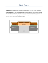
J-BOX RELOCATION
NOTE: If factory location of J-Box is acceptable, go to next
section (J-Box Cover Installation).
NOTE: On 14″ wide casing models, the J-Box shall not be
relocated to other side of furnace casing when the vent pipe is
routed within the casing.
1. Remove screws holding auxiliary J-box. (See Fig. 22.)
2. Cut wire tie on loop in wires to J-box.
3. Locate box to desired location.
4. Fasten J-Box to casing with screws.
5. Route J-box wires within furnace away from sharp edges and
hot surfaces.
ELECTRICAL CONNECTION TO J-BOX
If manual disconnect switch is to be mounted on furnace,
select a location where a drill or fastener will not contact
electrical or gas components.
1. Attach electrical box to J-Box bracket.
2. Route wires through hole in electrical box and J-Box bracket.
3. Secure ground wire to green screw on J-Box bracket.
4. Connect line voltage leads as shown in Fig. 24.
FOR POWER CORD INSTALLATION
Power cords must be able to handle the electrical requirements
listed in Table 5. Refer to power cord manufacturer’s listings.
→ Table 5—Electrical Data
UNIT SIZE
VOLTS-
HERTZ-
PHASE
OPERATING
VOLTAGE RANGE
MAXIMUM
UNIT AMPS
UNIT
AMPACITY#
MAXIMUM
WIRE LENGTH (FT)‡
MAXIMUM
FUSE OR CKT BKR
AMPS†
MINIMUM
WIRE GAGE
Maximum* Minimum*
045-08/024045 115-60-1 127 104 5.6 7.77 47 15 14
045-12/036045 115-60-1 127 104 7.0 9.47 39 15 14
070-08/024070 115-60-1 127 104 5.0 7.06 52 15 14
070-12/036070 115-60-1 127 104 6.7 9.19 40 15 14
070-16/048070** 115-60-1 127 104 9.8 12.59 28 15 14
090-14/042090 115-60-1 127 104 8.1 10.83 34 15 14
090-16/048090 115-60-1 127 104 9.8 12.95 28 15 14
090-20/060090** 115-60-1 127 104 12.9 17.60 34 20 12
110-12/036110 115-60-1 127 104 8.2 10.75 34 15 14
110-16/048110 115-60-1 127 104 10.1 13.12 28 15 14
110-22/066110 115-60-1 127 104 13.7 17.62 32 20 12
135-16/048135 115-60-1 127 104 10.1 13.12 28 15 14
135-22/066135 115-60-1 127 104 14.4 18.55 30 20 12
155-22/060155 115-60-1 127 104 15.0 19.33 29 20 12
* Permissible limits of the voltage range at which the unit operates satisfactorily.
# Unit ampacity = 125 percent of largest operating component’s full load amps plus 100 percent of all other potential operating components’ (EAC, humidifier, etc.) full load
amps.
† Time-delay type is recommended.
‡ Length shown is as measured 1 way along wire path between unit and service panel for maximum 2 percent voltage drop.
** Preliminary
Fig. 22—Relocating J-Box
A02099
TWO
16

1. Route listed power cord through hole in J-Box.
2. Secure power cord to J-Box bracket with a strain relief
bushing or a connector approved for the type of cord used.
3. Secure ground wire to green screw on J-Box bracket.
4. Connect line voltage leads as shown in Fig. 24.
FOR BX CABLE INSTALLATION
1. Route BX cable to hole in J-Box.
2. Secure BX cable to J-Box bracket with connectors approved
for the type of cable used.
3. Secure ground wire to green screw on J-Box bracket.
4. Connect line voltage leads as shown in Fig. 24.
J-BOX COVER INSTALLATION
1. Remove J-Box cover from blower access door on furnace and
reinstall blower access door screw.
2. Fold tab on J-box cover to bracket with pliers.
3. Insert tab of J-box cover into slot of J-box bracket.
4. Secure J-Box cover to bracket with screw provided.
5. Remove U-shaped cut-out from outer door to clear J-box.
24-V WIRING
Make field 24-v connections at the 24-v terminal strip. (See Fig.
23.) Connect terminal Y as shown in Fig. 24 for proper cooling
operation. Use only AWG No. 18, color-coded, copper thermostat
wire.
The 24-v circuit contains an automotive-type, 3-amp fuse located
on the control. Any direct shorts during installation, service, or
maintenance could cause this fuse to blow. If fuse replacement is
required, use ONLY a 3-amp fuse of identical size.
ACCESSORIES
1. Electronic Air Cleaner (EAC)
Connect an accessory Electronic Air Cleaner (if used) using
1/4-in female quick connect terminals to the two male 1/4-in
quick-connect terminals on the control board marked EAC-1
and EAC-2. The terminals are rated for 115 VAC, 1.0 amps
maximum and are energized during blower motor operation.
2. Humidifier (HUM)
Connect an accessory 24 VAC, 0.5 amp maximum humidifier
(if used) to the 1/4-in male quick-connect HUM terminal and
C
OM-24V screw terminal on the control board thermostat strip.
The HUM terminal is energized when pressure switch (PRS)
closes.
NOTE: A field-supplied, 115-v controlled relay connected to
EAC terminals may be added if humidifier operation is desired
during blower operation.
Fig. 23—Furnace Control
A02100
BLW
NUETRAL
STATUS CODE LED
SEC-2 SEC-1
EAC-2 L2
FUSE 3-AMP
0.5 AMP@24VAC
HUM
TEST/TWIN
G Com W Y R
24V
120 180
90 150
BLOWER OFF-DELAY
PLT 1
COOL HEAT
SPARE-1 SPARE-2
EAC-1
1-AMP@
115VAC
PR-1
L1
PL2 1
24-V THERMOSTAT
TERMINALS
3-AMP FUSE
LED OPERATION &
DIAGNOSTIC LIGHT
115-VAC(L2)NEUTRAL
CONNECTIONS
COOL
HEAT
SPARE-1
SPARE-2
BLOWER SPEED
SELECTION TERMINALS
EAC-1 TERMINAL
(115-VAC 1.0 AMP MAX.)
115 VAC (L1) LINE
VOLTAGE CONNECTION
PL2-HOT SURFACE
IGNITER & INDUCER
MOTOR CONNECTOR
PL1-LOW VOLTAGE MAIN
HARNESS CONNECTOR
TRANSFORMER 24-VAC
CONNECTIONS
HUMIDIFIER TERMINAL
(24-VAC 0.5 AMP MAX.)
TWINNING AND/OR
COMPONENT TEST
TERMINAL
BLOWER OFF-DELAY
J2
J2 JUMPER
PLT
17

DO NOT connect furnace control HUM terminal to HUM
(humidifier) terminal on Thermidistat™, Zone Controller or
similar device. See Thermidistat™, Zone Controller, thermo-
stat, or controller manufacturer’s instructions for proper
connection.
Step 8—Venting
The furnace shall be connected to a factory built chimney or vent
complying with a recognized standard, or a masonry or concrete
chimney lined with a lining material acceptable to the authority
having jurisdiction. Venting into an unlined masonry chimney or
concrete chimney is prohibited.
When an existing furnace is removed or replaced in a venting
system, the venting system may not be properly sized to vent the
attached appliances. An improperly sized Category I venting
system could cause the formation of condensate in the furnace and
vent, leakage of condensate and combustion products, and spillage
of combustion products into the living space, etc.
Fig. 24—Heating and Cooling Application Wiring Diagram with 1–Stage Thermostat
A99440
115-V FIELD-
SUPPLIED
DISCONNECT
AUXILIARY
J-BOX
24-V
TERMINAL
BLOCK
THREE-WIRE
HEATING-ONLY
FIVE WIRE
NOTE 1
NOTE 2
FIELD-SUPPLIED
DISCONNECT
CONDENSING
UNIT
TWO
WIRE
FURNACE
C
O
N
T
R
O
L
R
G
COM
WCR GY
GND
GND
FIELD 24-V WIRING
FIELD 115-, 208/230-, 460-V WIRING
FACTORY 24-V WIRING
FACTORY 115-V WIRING
208/230- OR
460-V
THREE
PHASE
208/230-V
SINGLE
PHASE
BLOWER DOOR SWITCH
WHT
BLK
WHT
BLK
NOTES: Connect Y-terminal in furnace as shown for proper blower operation.
Some thermostats require a "C" terminal connection as shown.
If any of the original wire, as supplied, must be replaced, use
same type or equivalent wire.
W
Y/Y2
GND
THERMOSTAT
TERMINALS
1.
2.
3.
18
→
→

CARBON MONOXIDE POISONING HAZARD
Failure to follow the steps outlined below for each appliance
connected to the venting system being placed into operation
could result in carbon monoxide poisoning or death.
The following steps shall be followed for each appliance
connected to the venting system being placed into operation,
while all other appliances connected to the venting system are
not in operation:
1. Seal any unused openings in venting system.
2. Inspect the venting system for proper size and horizontal
pitch, as required in the National Fuel Gas Code, ANSI
Z223.1/NFPA 54 or the CSA B149.1, Natural Gas and
Propane Installation Codes and these instructions. Deter-
mine that there is no blockage or restriction, leakage,
corrosion and other deficiencies, which could cause an
unsafe condition.
3. As far as practical, close all building doors and windows
and all doors between the space in which the appliance(s)
connected to the venting system are located and other
spaces of the building.
4. Close fireplace dampers.
5. Turn on clothes dryers and any appliance not connected to
the venting system. Turn on any exhaust fans, such as
range hoods and bathroom exhausts, so they are operating
at maximum speed. Do not operate a summer exhaust fan.
6. Follow the lighting instructions. Place the appliance being
inspected into operation. Adjust the thermostat so appli-
ance is operating continuously.
7. Test for spillage from draft hood equipped appliances at the
draft hood relief opening after 5 minutes of main burner
operation. Use the flame of a match or candle.
8. If improper venting is observed during any of the above
tests, the venting system must be corrected in accordance
with the National Fuel Gas Code, ANSI Z223.1/NFPA 54
and/or CSA B149.1, Natural Gas and Propane Installation
Codes.
9. After it has been determined that each appliance connected
to the venting system properly vents when tested as
outlined above, return doors, windows, exhaust fans,
fireplace dampers and any other gas-fired burning appli-
ance to their previous conditions of use.
Vent system or vent connectors may need to be resized. For any
other appliances when resizing vent systems or vent connectors,
system or connector must be sized to approach minimum size as
determined using appropriate table found in the NFGC or NSC-
NGPIC.
GENERAL VENTING REQUIREMENTS
Follow all safety codes for proper vent sizing and installation
requirements, including local building codes, the National Fuel
Gas Code (NFGC) ANSI Z223.1-2002/NFPA 54-2002, Parts 7 and
13 in the United States or the National Standard of Canada, Natural
Gas and Propane Installation Code (NSCNGPIC) CSA-B149.1-00,
Section 7 and Appendix C in Canada.
These furnaces are design-certified as Category I furnaces in
accordance with ANSI Z21.47/CSA 2.3-2001 and operate with a
non-positive vent static pressure to minimize the potential for vent
gas leakage. Category I furnaces operate with a flue loss not less
than 17 percent to minimize the potential for condensation in the
venting system. These furnaces are approved for common venting
and multi-story venting with other fan assisted or draft hood
equipped appliances in accordance with the NFCG or the NSC-
NGPIC.
The following information and warning must be considered in
addition to the requirements defined in the NFGC and the
NSCNGPIC.
1. If a vent (common or dedicated) becomes blocked, the furnace
will be shut off by the draft safeguard switch located on the
vent elbow.
Do not bypass the draft safeguard switch, as an unsafe
condition could exist which must be corrected. Failure to
follow this warning could result in a build-up of carbon
monoxide and lead to personal injury or death.
2. Do not connect this appliance to a single-wall dedicated or
common vent. The dedicated or common vent is considered to
be the vertical portion of the vent system that terminates
outdoors.
3. Vent connectors serving Category I furnaces shall not be
connected into any portion of a mechanical draft system
operating under positive pressure.
4. In the US, do not vent this appliance with any solid fuel
burning appliance. In Canada, check with the authority having
jurisdiction for approval on use with solid fuel burning
appliance.
5. Category I furnaces must be vented vertically or nearly
vertically unless equipped with a listed power ventor.
6. Do not vent this appliance into an unlined masonry chimney.
Refer to Chimney Inspection Chart, Fig. 25.
MASONRY CHIMNEY REQUIREMENTS
These furnaces are CSA design-certified for use in exterior
clay tile-lined masonry chimneys with a factory accessory
Chimney Adapter Kit. Refer to the furnace rating plate for
correct kit usage. The Chimney Adapter Kits are for use with
ONLY furnaces having a Chimney Adapter Kit number
marked on the furnace rating plate.
If a clay tile-lined masonry chimney is being used and it is exposed
to the outdoors below the roof line, relining might be required.
Chimneys shall conform to the Standard for Chimneys, Fireplaces,
Vents, and Soild Fuel Burning Appliances ANSI/NFPA 211-2000
in the United States and to a Provincial or Territorial Building
Code in Canada (in its absence, the National Building Code of
Canada) and must be in good condition.
U.S.A.-Refer to Sections 13.1.9 and 13.2.20 of the NFGC or the
authority having jurisdiction to determine whether relining is
required. If relining is required, use a properly sized listed metal
liner, Type-B vent, or a listed alternative venting design.
19
→
→
→
/