Page is loading ...

4KEX100-KVM-H2
HDMI 2.0 HDBaseT Extender with USB 2.0
User Manual


Disclaimers
The information in this manual has been carefully checked and is believed to be
accurate. AV Access Technology Limited assumes no responsibility for any
infringements of patents or other rights of third parties which may result from its
use.
AV Access Technology Limited assumes no responsibility for any inaccuracies that
may be contained in this document. AV Access Technology Limited also makes no
commitment to update or to keep current the information contained in this
document.
AV Access Technology Limited reserves the right to make improvements to this
document and/or product at any time and without notice.
Copyright
Copy, Reproduce, Distribute and/or Edit of this document or part of it as well as
utilization of its contents and communication thereof to others without express
authorization are prohibited. Offenders will be held liable for payment of damages.
All rights created by patent grant or registration of a utility model or design patent
are reserved. Copyright ©2017 AV Access Technology Limited All rights reserved.
Trademarks Notice
All products or service names mentioned in this document may be trademarks of
the companies with which they are associated.
Contact Us
Business inquiry: services@avaccess.com
Technical problems: suppo[email protected]

Important Safety Instructions
Do not expose this device to rain, moisture, dripping or splashing. No objects
filled with liquids, such as vases, shall be placed on the device.
Do not install or place this unit in a bookcase, built-in cabinet, or in another
confined space. Ensure the unit is well ventilated.
To prevent risk of electric shock or fire hazard due to overheating, do not
obstruct the unit’s ventilation openings with newspapers, tablecloths,
curtains, or similar items.
Do not install near any heat sources such as radiators, heat registers, stoves,
or other device (including amplifiers) that produce heat.
Do not place sources of naked flames, such as lighted candles, on the unit.
Clean this device only with dry cloth.
Unplug this device during lightning storms or when unused for long periods
of time.
Protect the power cord from being walked on or pinched, particularly at
plugs.
Only use attachments / accessories specified by the manufacturer.
Refer all servicing to qualified service personnel

www.avaccess.com 1 services@avaccess.com
Table of Contents
Introduction .......................................................................................................... 2
Features .................................................................................................................................... 2
Package Contents .................................................................................................................. 3
Panel .......................................................................................................................................... 4
Front Panel...................................................................................................................... 4
Rear Panel ....................................................................................................................... 5
Installation and Application................................................................................. 7
Brackets Installation .............................................................................................................. 7
Steps to install the device in a suitable location ................................................. 7
IR Cable Operation ................................................................................................................ 8
Cable Type ...................................................................................................................... 8
Using the IR Emitter ..................................................................................................... 8
Application ............................................................................................................................ 11
RS232 Pass-Through ........................................................................................... 14
Specifications ..................................................................................................... 15
Trouble Shooting ................................................................................................ 17
Warranty ............................................................................................................. 18

Introduction
www.avaccess.com 2 services@avaccess.com
Introduction
Overview
4KEX100-KVM-H2 is a 100m/330ft 4K@60 444 HDR HDBaseT Extender. The kit is
HDCP 2.2 compliant and supports 4K/UHD video @ 60 Hz with 4:4:4 chroma
sampling, as well as HDMI data rates up to 18 Gbps. It provides HDMI transmission
up to 330 feet (100 meters) over category cable. It supports bi-directional
Ethernet pass-through, RS-232, bi-directional IR control and bi-direction analog
audio. Built-in one-way PoH, the receiver can be powered by the transmitter. The
extender features visually lossless VESA Display Stream Compression (DSC) to
enable HDR and 4K/60 4:4:4 video signal extension over HDBaseT. It also supports
one USB host and 4 USB device ports switchable for KVM usage.
Features
HDMI Input/Output supports resolutions up to 4K@60Hz 4:4:4 8 bit
Visual lossless DSC compression solution
HDCP 2.2 compliant
Supports HDR formats including HDR10 and Dolby Vision
Transmits HDBaseT signal up to 100m/330ft for 4K and 1080P via a single
Cat 6/6a/7 cable
Transmits HDBaseT signal up to 90m/295ft for 4K and 100m/330ft for 1080P
via a single Cat 5e cable
Bi-directional IR, RS232 pass-through over HDBaseT
Provides one USB Host and four USB Device ports for remote KVM control
Supports one-way standard PoH, one power adapter on the transmitter can
power both units
Automatic EDID management

Introduction
www.avaccess.com 3 services@avaccess.com
Note: The kit supports Dolby Vision only if the resolution is less than or equal to
4K@30Hz.
Package Contents
Before you start the installation of the product, please check the package
contents:
Transmitter x 1
Receiver x1
Power Adapter (DC 12V 3A) x 1
AC Power Cord with US Pins x 1
IR Emitter x1
Broadband IR Receiver (30 KHz ~ 50 KHz) x 1
Phoenix Male Connectors (3.5mm, 3 Pins) x 2
USB 2.0 Type-B to Type-A Cable (L=1.5m) x 1
Mounting Brackets (with Screws) x 4
User Manual x 1

Introduction
www.avaccess.com 4 services@avaccess.com
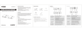
Panel
Front Panel
Transmitter & Receiver
1 2 3 4 5 6
No. Name Description
1 USB Control Switch to USB Host or USB Device mode.
2 Power LED On: Transmitter (or Receiver) is powered on.
Off: Transmitter (or Receiver) is powered off.
3 Status LED Blinking: Transmitter (or Receiver) is working properly.
Off: Transmitter (or Receiver) is not working properly.
4 HDCP LED
On: HDCP-protected content is being transmitted.
Blinking: Non-
HDCP protected content is being
transmitted.
Off: No content is being transmitted.
5 Link LED
On: The link between transmitter and receiver is
normal.
Blinking/Off: Link error or no link.
6 RS232
Program:
Upgrade the transmitter/receiver through RS232 port.
Pass Through (Default Setting):
RS232 port is used for RS232 pass-through.

Introduction
www.avaccess.com 5 services@avaccess.com
Rear Panel
Transmitter
1 2 3 4 5 6 78910 11
No. Name Description
1 DC 12V Connect to the power adapter provided.
2 HDBT Out Connect to HDBT In port of the receiver with a Cat
5e/6/6a/7 cable.
3 RS232 For RS232 pass-through or firmware upgrade.
4 HDMI In Connect to an HDMI source using an HDMI cable.
5 Audio In Analog audio input, connect to an audio source device.
6 Audio Out Analog audio output, connect to an audio receiving
device.
7 USB Device
Connect to USB devices (e.g. keyboard, mouse,
interactive whiteboard).
Note: Ensure the USB Mode Switch on front panel is set
to "USB Device" position.
8 USB Host
Connect to a USB-host device (e.g. PC).
Note: Ensure the USB Mode Switch on front panel is set
to "USB Host" position.
9 IR In Connect the broadband IR receiver provided.
10 IR Out Connect to the IR emitter provided.
11 Ethernet Connect an Ethernet device for ethernet pass through.

Introduction
www.avaccess.com 6 services@avaccess.com
Receiver
1 2 3 4 5 6 7 8910 11
No. Name Description
1 DC 12V Connect to the power adapter provided.
2 HDBT In Connect to HDBT Out of the transmitter with a Cat
5e/6/6a/7 cable.
3 RS232 For RS232 pass-through or firmware upgrade.
4 HDMI Out Connect to an HDMI display using an HDMI cable.
5 Audio In Analog audio input, connect to an audio source device.
6 Audio Out Analog audio output, connect to an audio receiving
device.
7 USB Device
Connect to USB devices (e.g. keyboard, mouse,
interactive whiteboard).
Note: Ensure the USB Mode Switch on front panel is set
to "USB Device" position.
8 USB Host
Connect to a USB-host device (e.g. PC).
Note: Ensure the USB Mode Switch on front panel is set
to "USB Host" position.
9 IR In Connect the broadband IR receiver provided.
10 IR Out Connect to the IR emitter provided.
11 Ethernet Connect an Ethernet device for ethernet pass through.

Installation and Application
www.avaccess.com 7 services@avaccess.com
Installation and Application
Brackets Installation
Note: Before installation, please ensure 4KEX100-KVM-H2 is disconnected from
the power source.
Steps to install the device in a suitable location
1. Attach the installation bracket to the enclosure using the screws that were
provided in the package separately. The bracket height can be adjusted
up/down or bracket face up or down.
2. The bracket is attached to the enclosure as shown.
3. Repeat steps from 1 to 2 for the other side of the unit.
4. Attach the brackets to the surface you want to hold the unit against using
the screws (provided by others).
5. Repeat steps from 1 to 4 to install the receiver.

Installation and Application
www.avaccess.com 8 services@avaccess.com
IR Cable Operation
Cable Type
IR Emitter: Connect to the "IR Out" port of the device.
Broadband IR Receiver (30-50 KHz): Connect to the "IR In" port of the device.
Using the IR Emitter
1. Insert the IR emitter plug into the “IR Out” jack located on the transmitter or
receiver.
2. Example 1: Attach the IR emitter head directly with the adhesive tape
provided near the IR receiver window (e.g. at the distance of 1cm) on the
device you want to control.
IR Receiver
IR Emitter
Controlled Device
Example 2: You can also place the IR emitter in front of the IR receiver
window on the controlled device.

Installation and Application
www.avaccess.com 9 services@avaccess.com
IR Receiver
IR Emitter
Controlled Device
IR Signal Emission
Example 3: When connected to control system, ensure the IR emitter is over
against the IR receiver's front side instead of its flat side (see below picture):
IR Receiver IR Emitter
Flat Side
Transmitter
(Receiver)
Control
System
IR Receiver IR Emitter
Flat Side
Transmitter
(Receiver)
Control
System
Please refer to your device's user guide to find out where the IR receiver is
on your connected device.
For example, the IR receiver for Apple TV/Amazon Fire TV/TIVO BOLT is
shown as below:

Installation and Application
www.avaccess.com 10 services@avaccess.com
IR Receiver
TIVO BOLT
Note: Products from AV Access do not support Bluetooth control, the introduction
above applies to device with IR control capability only. Here is a list about
different devices' control method.
No. Device Control Method
1 NVDIA 2571 Player Bluetooth/USB
2 Amazon Fire TV with UHD HDR Bluetooth
3 Amazon Fire TV IR
4 ROKU Ultra Player Bluetooth
5 Apple TV 3rd IR
6 Apple TV 4th IR
7 Apple 4K TV 5th Bluetooth
8 Xbox one S Bluetooth/USB
9 Xbox one X Bluetooth/USB
10 TIVO BOLT IR
11 NINTENDO SWITCH HAC-001
Game Console Bluetooth/USB
12 PS4 Pro Bluetooth/USB
13 Blu-ray Player IR

Installation and Application
www.avaccess.com 11 services@avaccess.com
Application
Blu-ray Player
Player Remote
Transmitter
Receiver
1
Connect an HDMI source
device to HDMI In of the
transmitter using a
high-quality HDMI cable
2Connect an HDMI
display device to
HDMI Out of the
receiver using a
high-quality HDMI
cable
Connect to the
power adapter
provided.
Note: The
receiver can be
powered by the
transmitter.
3Connect HDBT Out of the transmitter to
HDBT In of the receiver with Cat 5e/6/6a/7 cable.
4
Connect the
IR Emitter cable
to IR Out port
or connect the IR
receiver cable to
IR In port of
the transmitter.
5Connect the IR receiver
cable to IR In port
or connect the IR
Emitter cable to
IR Out port of
the receiver
6
6
Power Adapter
Display
Application 1

Installation and Application
www.avaccess.com 12 services@avaccess.com
Transmitter
Receiver
6
Power Adapter
Display
PC
Internet
1
Connect an HDMI source
device to HDMI In of the
transmitter using a
high-quality HDMI cable
2
Connect an HDMI
display device to
HDMI Out of the
receiver using a
high-quality HDMI
cable
3
Connect HDBT Out of the transmitter to
HDBT In of the receiver with Cat 5e/6/6a/7 cable.
4
Connect to USB
Host/Device
5
Connect to USB
Device/Host
7
Connect to a PC
6
Connect to
the local area
network.
Connect to the
power adapter
provided.
Note: The
receiver can be
powered by the
transmitter.
8
Application 2
Warnings:
Before wiring, disconnect the power from all devices.
During wiring, connect and disconnect the cables gently.
Additional Control Options:
1. Connect USB Host/Device:
Switch to "USB Host" mode on transmitter's front panel (ensure the
connected receiver is switched to "USB Device" mode): Connect a USB
host device to USB Host port of the transmitter and USB devices to
USB Device port of the receiver for remote KVM control.
Switch to "USB Device" mode on transmitter's front panel (ensure the
connected receiver is switched to "USB Host" mode): Connect USB

Installation and Application
www.avaccess.com 13 services@avaccess.com
devices to USB Device port of the transmitter and a USB host device to
USB Host port of the receiver for remote KVM control.
2. Ethernet Pass-through
Connect the Ethernet port of the transmitter/receiver to the local area
network.
Connect a PC to the “Ethernet port of the receiver/transmitter, the PC
can connect to the local area network.

RS232 Pass-Through
www.avaccess.com 14 services@avaccess.com
RS232 Pass-Through
RS232 port can be used for bi-directional RS232 signal pass-through between
transmitter and receiver.
Steps to set up for RS232 pass-through:
Switch the "RS232" on front panel of the transmitter and receiver to "Pass
Through" mode.
Connect a RS232 Master (or Slave) Device to RS232 port of transmitter with
a RS232 cable.
Connect a RS232 Slave (or Master) Device to RS232 port of receiver with a
RS232 cable.
Connect HDBT Out of the transmitter to HDBT In of the receiver with a Cat
5e/6/7 cable.
When all is set, RS232 signal can be passed through bi-directionally between two
RS232 devices.
Transmitter
Receiver
RS232 Device
RS232 Device
Cat x

Specifications
www.avaccess.com 15 services@avaccess.com
Specifications
Technical
Video Signal HDMI with 4K@60Hz 4:4:4, HDCP 2.2
Input/Output
Resolution Support
800x6008, 1024x7688, 1280x7208, 1280x7688,
1280x8008, 1280x9608, 1280x10248, 1360x7688,
1366x7688, 1440x9008, 1600x9008, 1600x12008,
1680x10508, 1920x10808, 1920x12008, 2560x14408,
2560x16008, 3840x2160P2,3,5,6,8
1 = at 23.98 Hz, 2 = at 24 Hz, 3 = at 25 Hz, 4 = at 29.97
Hz, 5 = at 30 Hz, 6 = at 50 Hz, 7 = at 59.94 Hz,
8 = 60 Hz;
HDR Format
Supported
HDR 10
Dolby Vision (with resolutions under 4K@30Hz)
Audio Format
Supported
HDMI: Fully supports audio formats in HDMI 2.0
specification, including
PCM, Dolby TrueHD,
Dolby Atmos, DTS-HD Master Audio, DTS:X
3.5mm Mini Jack: stereo
Max Data Rate 18 Gbps
General
Operating Temperature 0°C to + 45°C (32 to + 113 °F)
Storage Temperature -20 to +70°C (-4 to + 158 °F)
Humidity 20% to 90%, non-condensing
Power Consumption
(Maximum) 17.8W (pair)
Device Dimensions
(W x H x D)
245mm x 25mm x 90.2mm/
9.6’’ x 1’’ x 3.55’’
Product Weight Transmitter/Receiver: 0.66kg/1.45lb

Specifications
www.avaccess.com 16 services@avaccess.com
Transmission Distance
Note: Straight-through Category cables wired to T568B standard is
recommended.
Cable Range Supported Video
Cat 5e 100m/330ft 1080P@60Hz 36bpp
90m/295ft 1080P@60Hz 48bpp
1080P@60Hz 3D
4K@30Hz
4K@60Hz
Cat 6/6a/7 100m/330ft
HDMI
Input/Output:15m/50ft 1080P@60Hz 24bpp
Input: 10m/33ft
Output: 15m/50ft
4K@30Hz
Input/Output: 5m/16ft 4K@60Hz
/