Vega EL 8 Product information

Type
Product information

This manual is also suitable for

Product information
Conductive
Level detection in liquid
VEGAKON 61
VEGAKON 66
Probes EL 1, 3, 4, 6, 8
Document ID: 33064
2
Contents
Conductive
33064-EN-160930
Contents
1 Description of the measuring principle ............................................................................................................................................................... 3
2 Type overview ......................................................................................................................................................................................................... 4
3 Mounting instructions ........................................................................................................................................................................................... 6
4 Electrical connection ............................................................................................................................................................................................. 7
5 Adjustment ............................................................................................................................................................................................................. 9
6 Dimensions ...........................................................................................................................................................................................................11
Take note of safety instructions for Ex applications
Please note the Ex specic safety information that you can nd at www.vega.com and that comes with each instrument. In hazardous areas
you should take note of the appropriate regulations, conformity and type approval certicates of the sensors and power supply units. The sen-
sors must only be operated on intrinsically safe circuits. The permissible electrical values are stated in the certicate.
3
Description of the measuring principle
Conductive
33064-EN-160930
1 Description of the measuring principle
Measuring principle
Conductive probes are used for level detection in conductive liquids.
The instruments are designed for industrial use in all areas of process
technology.
Conductive probes detect the product resistance when their electrodes
get covered by the product. A small alternating current, measured contin-
uously by the electronics of the compact instrument or a separate signal
conditioning instrument, is checked for amplitude and phase position and
converted into a switching signal.
A conductive probe consists of a ground electrode and a level-related
measuring electrode.
The switching signal is determined by the length or mounting position of
the respective measuring electrode.
In conductive vessels, the vessel wall can be used as the ground
electrode. The measuring probe can then consist of only one measuring
electrode.
The sensors are maintenance free and rugged and can be implemented
in all areas of industrial measurement engineering.
1.2 Application examples
Overow protection
Measuring system for detection of the max. level in an electrically con-
ductive vessel (e.g. as overow protection)
Fig. 1: Overow protection
Simple, inexpensive level detection, e.g. as overow protection in watery
liquids.
Advantages:
Easy, reliable sensors
Small mounting dimensions
Two-point control (e.g. as pump control)
Due to the many possible ways of application, conductive level switches
are ideal for all measuring tasks in connection with water and aqueous
solutions. The large number of electrical and mechanical versions guar-
antees simple integration into existing processes.
Pump control is a frequent application in the area of water and waste
water.
To empty a pump sump automatically with a pump when a certain level
is exceeded and to switch the pump o again when the min. level is
reached, the pump can be controlled with a conductive measuring probe.
Fig. 2: Pump control with an EL 3 conductive measuring probe
Advantages:
Up to ve switching points with one sensor possible
Dry run protection in pipelines
Thanks to its virtually front-ush conical electrode, the conductive level
switch VEGAKON 61 is ideal for use in pipelines. Its ow-ecient prole
does not change the pipe cross section and thus prevents turbulence.
The VEGAKON 61 measures the eld strength at its tip, and is thus
insensitive to buildup.
VEGAKON 61 calibrates itself automatically and therefore needs no
adjustment.
Fig. 3: Dry run protection in pipelines
Advantages:
Suitable for very adhesive products
Adjustment free
Causes no turbulence
Does not change pipe cross sectional area
Robust and abrasion resistant
4
Type overview
Conductive
33064-EN-160930
2 Type overview
VEGAKON 61 VEGAKON 66
Applications Conductive liquids, pipelines Conductive liquids
Version Compact level switch, partly insulated Compact level switch, rod - partly insulated
Insulation PTFE PP
Length -- 0.12 … 4 m (0.394 … 13.12 ft)
Process tting Thread G1, cone, Tuchenhagen Thread G1½
Process temperature -40 … +150 °C (-40 … +302 °F) -40 … +100 °C (-40 … +212 °F)
Process pressure -1 … 25 bar/-100 … 2500 kPa (-14.5 … 363 psigg) -1 … 6 bar/-100 … 600 kPa (-14.5 … 87 psig)
EL 1 EL 3 EL 4
Applications Conductive liquids Conductive liquids Conductive liquids
Version
1)
Rod - partly insulated Rod - partly insulated Rod - partly insulated
Insulation PTFE PTFE PP
Length 0.04 … 4 m (0.131 … 13.12 ft) 0.1 … 4 m (0.328 … 13.12 ft) 0.1 … 4 m (0.328 … 13.12 ft)
Process tting Thread G1½ Thread G1½ Thread G1½
Process temperature -50 … +130 °C (-58 … +266 °F) -50 … +130 °C (-58 … +266 °F) -20 … +100 °C (-4 … +212 °F)
Process pressure -1 … 63 bar/-100 … 6300 kPa (-
14.5 … 914 psig)
-1 … 63 bar/-100 … 6300 kPa (-
14.5 … 914 psig)
-1 … 6 bar/-100 … 600 kPa (-
14.5 … 87 psig)
1)
For connection to a VEGATOR signal conditioning instrument.
5
Type overview
Conductive
33064-EN-160930
EL 6 EL 8
Applications Conductive liquids Conductive liquids
Version
2)
Cable - partly insulated Rod - partly insulated
Insulation FEP PE
Length 0.22 … 50 m (0.722 … 164.04 ft) 0.03 … 1 m (0.098 … 3.281 ft)
Process tting Thread G1½ Thread G1½
Process temperature -20 … +100 °C (-4 … +212 °F) -10 … +60 °C (+14 … +140 °F)
Process pressure -1 … 6 bar/-100 … 600 kPa (-14.5 … 87 psig) -1 … 6 bar/-100 … 600 kPa (-14.5 … 87 psig)
2)
For connection to a VEGATOR signal conditioning instrument.
6
Mounting instructions
Conductive
33064-EN-160930
3 Mounting instructions
Switching point
Mount the probe in such a way that the rod or cable electrodes do not
touch the vessel wall during operation.
Agitators
Due to agitators, vibrations or similar, the probe can be subjected to
strong lateral forces.
Excessive system vibration or shocks, e.g. caused by agitators or tur-
bulence in the vessel (e.g. from uidisation) can cause the rod probe to
vibrate in resonance. This can lead to increased material stress. Should a
longer rod probe be necessary, you can provide a suitable insulated sup-
port or guy directly above the end of the probe to stabilise it.
In case of strong product movements, foam generation and ow in the
vessel, the probe can be also mounted in bypass tubes.
1
2
1
2
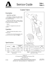
Fig. 11: Fasten the probe
1 Measuring probe
2 Plastic socket on the probe end
3 Measuring probe
4 Plastic socket laterally mounted
Inowing medium
If the conductive sensors are mounted in the lling stream, unwanted
false measuring signals may be triggered. For this reason, mount the
instruments at a position in the vessel where no disturbances, e.g. from
lling openings, agitators, etc., can occur.
Fig. 12: Inowing medium
Pressure/Vacuum
The process tting must be sealed if there is gauge or low pressure in
the vessel. Check if the seal material is resistant against the measured
product and the process temperature.
Insulating measures in metal vessels such as e.g. covering the thread
with teon tape can interrupt the necessary electrical connection to the
vessel. Ground the probe on the vessel.
Shorten the probe
The rods of the probe can be shortend individually.
Metal vessel
If probes without ground electrode are used, you must make sure that the
mechanical connection of the probe is connected electrically conductive
to the vessel to ensure sucient grounding.
Use conductive seals such as e.g. copper, lead etc.
Insulating measures such as e.g. covering the thread with teon tape can
interrupt the necessary electrical connection. If this is necessary, use the
ground terminal on the housing to connect the instrument with the vessel.
A ground electrode must be provided for probes EL 4 and 6 as well as
with VEGAKON 66.
Non-conductive vessels
Generally use probes with a ground electrode in non-conductive vessels,
e.g. plastic tanks.
Horizontal mounting
If you mount a VEGAKON 66 laterally, we recommend mounting it ap-
prox. 20° inclined so that the liquid medium can drain o more easily and
no buildup can generate on the isolation.
ca. 20°
Fig. 13: Horizontal mounting
Ground connection
If probes without ground electrode are used, you must make sure that the
mechanical connection of the probe is connected electrically conductive
to the vessel to ensure sucient grounding.
Use conductive seals, such as those made of copper or lead, etc. Insulat-
ing measures, such as covering the thread with Teon tape, can interrupt
the necessary electrical connection with metal vessels. For this reason,
ground the probe on the vessel or use a conductive seal material.
7
Electrical connection
Conductive
33064-EN-160930
4 Electrical connection
4.1 Preparing the connection
Note safety instructions
Always keep in mind the following safety instructions:
Connect only in the complete absence of line voltage
Take note of safety instructions for Ex applications
In hazardous areas you must take note of the respective regula-
tions, conformity and type approval certicates of the sensors and
power supply units.
Select power supply
Connect the operating voltage according to the following diagrams. The
oscillator with relay output is designed in protection class 1. To maintain
this protection class, it is absolutely necessary that the ground conductor
be connected to the internal ground terminal. Take note of the general
installation regulations. As a rule, connect VEGAKON to vessel ground
(PA), or in case of plastic vessels, to the next ground potential. On the
side of the housing there is a ground terminal between the cable entries.
This connection serves to drain o electrostatic charges. In Ex applica-
tions, the installation regulations for hazardous areas must be given
priority.
The data for power supply are specied in chapter "Technical data".
Select connection cable
VEGAKON and probes EL are connected with standard cable with round
cross section. An outer cable diameter of 5 … 9 mm (0.2 … 0.35 in)
ensures the seal eect of the cable gland.
If cable with a dierent diameter or wire cross section is used, exchange
the seal or use an appropriate cable connection.
In hazardous areas, only use approved cable connections for ap-
proved instruments.
Select connection cable for Ex applications
Take note of the corresponding installation regulations for Ex
applications.
4.2 Wiring plan VEGAKON 61, 66
Relay output
Is used to switch external voltage sources to relays, contactors, magnetic
valves, horns etc.
We recommend connecting VEGAKON in such a way that the switch-
ing circuit is open when there is a level signal, line break or failure (safe
state).
The relays are always shown in non-operative condition.
1
2
3 4
5
6
+
L1
-
N
1
2
Fig. 14: VEGAKON 61 - electronics with relay output
1 Relay output
2 Voltage supply
12
-
+
L1 N
345
678
1
2
Fig. 15: VEGAKON 66 - electronics with relay output
1 Relay output
2 Voltage supply
Transistor output
Is used to switch external voltage sources to relays, contactors, magnetic
valves, horns etc.
We recommend connecting VEGAKON in such a way that the switch-
ing circuit is open when there is a level signal, line break or failure (safe
state).
The instrument is used to control relays, contactors, magnet valves,
warning lights, horns as well as PLC inputs.
1
2
3 4
5
+-
Fig. 16: VEGAKON 61 - transistor output
12
-
+
34
Fig. 17: VEGAKON 66 - transistor output
The transistor switches the operating voltage of the electronic module to
the binary input of a PLC or an electrical load. Through dierent connec-
tions of the consumer (load), PNP or NPN action can be attained.
8
Electrical connection
Conductive
33064-EN-160930
1234 12345
+-
+-
+-
+-
5
1 2
Fig. 18: VEGAKON 61 - electronics with transistor output
1 NPN action
2 PNP action
1
2
34 1
2
34
+-
+-
+-
+-
1 2
Fig. 19: VEGAKON 66 - electronics with transistor output
1 NPN action
2 PNP action
4.3 Wiring plan EL 1, EL 3, EL 4, EL 6, EL 8
For connection to a signal conditioning instrument
You can nd the electrical connection of the conductive probes in the
product information manual "Signal conditioning instruments for conduc-
tive electrodes".
You can nd suitable signal conditioning instruments in chapter "Techni-
cal data".
Select connection cable
To ensure the seal eect of the cable gland, the conductive probes are
connected with standard cable with round cross-section. The outer diam-
eter of the cable is stated in chapter "Technical data".
Line monitoring with VEGATOR 131, 132, 631, 632
The line break monitoring or alarm function denes the function of the
signal conditioning instrument in case of failure.
To realize line break monitoring with the signal conditioning instruments
VEGATOR 131, 132, 631 and 632, a supplementary electronics must be
mounted in the connection housing of the probe.
When a fault message is generated, the switching output is simultane-
ously activated. Only failures of channel 1 are monitored.
The line break monitoring is required for probes with approval according
to WHG (WRA) or Ex.
The supplementary electronics for line break monitoring is available in
two dierent versions diering optically in the cable colours.
Cable colour red - in conjunction with a VEGATOR 632 signal condi-
tioning instrument
Cable colour blue - in conjunction with a VEGATOR 131, 132, 631
signal conditioning instrument
1
Fig. 20: Supplementary electronics for line break monitoring in conjunction with
VEGATOR 131, 132, 631, 632
1 Connection cable red - in conjunction with the VEGATOR 632 signal condition-
ing instrument
Connection cable blue - in conjunction with the VEGATOR 131, 132, 631 signal
conditionings instrument
1
3
2
Fig. 21: Mounting of the additional electronics for line break monitoring
1 Connection to terminal 1 (ground rod = longest rod)
2 Connection to terminal 2 (max. rod = shortest rod)
3 Additional electronics for line break monitoring
9
Adjustment
Conductive
33064-EN-160930
5 Adjustment
5.1 Adjustment elements VEGAKON 61 R, 61 T
6
5
4
3
1
2
max. 250V AC 5A 750VA
3A 500VA
20...72V DC
20...250V AC
L
N
+-
R
A
B
21
3
4
Fig. 22: Electronics module VEGAKON 61 R (relay output)
1 Type label
2 Control lamp (LED)
3 Connection terminals
4 Mode switch (A/B)
5
4
3
1
A
B
10 ... 55V DC lout _400mA
2
R
2
1
3
4
Fig. 23: Electronics module VEGAKON 61 T (transistor output)
1 Type label
2 Control lamp (LED)
3 Connection terminals
4 Mode switch (A/B)
Mode setting (4)
With the mode adjustment (A/B) you can change the switching condition
of the output. It allows you to set the required mode (A - max. detection or
overow protection, B - min. detection or dry run protection).
Signal lamp (2)
The signal lamp shows the switching status of the output and can be
checked with closed housing.
5.2 Adjustment elements VEGAKON 66 R, 66 T
876
5
4
3
1
2
max. 250V AC 5A 750VA
max. 250V DC 1A 54W
20...72V DC
20...250V AC
L
N
+-
R
KON E66R
max
min
K
TEST
0.1
TEST
300
100
30
0.3
1
3
10
A
2s
6s
12s
B
off
off
off
1
27
6
3
45
Fig. 24: Electronics module VEGAKON 66 R (relay output)
1 Connection terminals
2 Control lamp (LED)
3 Rotary switch: Adjustment of the conductivity value
4 Selection switch: Damping
5 Selection switch: Mode (A/B) VEGAKON
6 Type label
7 Tensile proving ring
KON E66T
FUNCTION
1
2
3
4PNP
+
-
1
2
3
4NPN
+
-
I out
max.400mA
10...55VDC
+-
3
4
1
2
max
min
K
TEST
0.1
TEST
300
100
30
0.3
1
3
10
A
2s
6s
12s
B
off
off
off
R
1
27
6
3
45
Fig. 25: Electronics module VEGAKON 66 T (transistor output)
1 Connection terminals
2 Control lamp (LED)
3 Rotary switch: Adjustment of the conductivity value
4 Selection switch: Damping
5 Selection switch: Mode (A/B) VEGAKON
6 Type label
7 Tensile proving ring
Signal lamp (2)
The signal lamp shows the switching status of the output and can be
checked with closed housing.
Rotary switch: Adjustment of the conductivity value (3)
With the rotary switch you can adjust the sensitivity of the instrumet. Posi-
tion 0.1 kΩ is less sensitive and switch position 300 kΩ is most sensitive.
10
Adjustment
Conductive
33064-EN-160930
Selection switch: Damping (4)
There are three switches on the DIL switch block by which you can adjust
the switching on and o delay. Thus prevents, e.g. the instrument from
permanent switching if the level is within the limits.
The delay refers to the switching status of both relay outputs.
With the switches (2 s, 6 s, 12 s) you can set the damping respectively in
the range of 0 to 20 seconds. The times of the activated timers add up. If
e.g. the switches 2 s and 12 s are activated, the damping will be 14 s.
Mode adjustment (5)
With the mode adjustment (A/B) you can change the switching condition
of the output. It allows you to set the required mode (A - max. detection or
overow protection, B - min. detection or dry run protection).
Tensile proving ring (7)
Loosen the holding screws of the electronics module. Fold the tensile
proving ring upward. With the tensile proving ring you can pul the elec-
tronics module out of the instrument housing.
5.3 Adjustment probes EL 1, EL 3, EL 4, EL 6, EL 8
The adjustment of probes EL is carried out via a suitable signal con-
ditioning instrument. The adjustment possibilities are specied in the
product information manual "Signal conditioning instruments for conduc-
tive probes".
11
Dimensions
Conductive
33064-EN-160930
6 Dimensions
VEGAKON 61
80 mm x 110 mm
(3.15" x 4.33")
~30 mm
(1.18")
75 mm
(2.95")
51 mm
(2.01")
52 mm
(2.05")
21 mm
(0.83")
28 mm
(1.10")
10 mm
(0.39")
G1A
SW 41mm
(1.61")
1 2
3
M20x1,5
Fig. 26: VEGAKON 61
1 Threaded version
2 Cone version
3 Temperature adapter
VEGAKON 66
L2
L3
L1
~75mm
(2.95")
ø4mm
(0.16")
85mm
(3.35")
92,5mm
(3.64")
112mm
(4.41")
24mm
(0.94")
G1½A
SW 60mm
(2.36")
M20x1,5
Fig. 27: VEGAKON 66 with three probes
L1 Length ground probe
L2 Length max. probe
L3 Length min. probe
EL 1
~43 mm
(1.69")
46 mm
(1.81")
ø10 mm
(0.39")
ø8 mm
(0.31")
54 mm
(2.13")
18 mm
(0.71")
SW 41 mm
(1.61")
G½A
L
L1
M16x1,5
Fig. 28: Conductive rod electrode EL 1
L Sensor length, see chapter "Technical data"
L1 Insulation length, see chapter "Technical data"
EL 3
M20x1,5
66mm
(2.59")
57mm
(2.24")
ø6 mm
(0.24")
59mm
(2.32")
80mm
(3.15")
20mm
(0.79")
SW 60mm
(2.36")
G1½A
L3
L1
L2
Fig. 29: Conductive multiple rod electrode EL 3
L1 Sensor length, see chapter "Technical data"
L2 Sensor length, see chapter "Technical data"
L3 Sensor length, see chapter "Technical data"
12
Dimensions
Conductive
33064-EN-160930
EL 4
66mm
(2.60")
62mm
(2.44")
4mm
(0.16")
55mm
(2.17")
78mm
(3.07")
22mm
(0.67")
SW 60mm
(2.36")
G1½A
L2
L3
L1
M20x1,5
Fig. 30: Conductive multiple rod electrode EL 4
L1 Sensor length, see chapter "Technical data"
L2 Sensor length, see chapter "Technical data"
L3 Sensor length, see chapter "Technical data"
EL 6
66mm
(2.59")
62mm
(2.44")
ø2,5 mm
(0.10")
ø12 mm
(0.47")
55mm
(2.17")
78mm
(3.07")
22mm
(0.87")
SW 60mm
(2.36")
G1½A
L2
L3
L1
M20x1,5
PP
1.4571
FEP
80mm
(3.15")
Fig. 31: Conductive multiple cable electrode EL 6
L1 Sensor length, see chapter "Technical data"
L2 Sensor length, see chapter "Technical data"
L3 Sensor length, see chapter "Technical data"
EL 8
30 mm
(1.18")
12 mm
(0.47")
9,3 mm
(0.37")
ø24 mm
(0.94")
ø6,8 mm
(0.27")
ø4 mm
(0.16")
27mm
(1.06")
SW 27mm
(1.06")
G½A
L
Fig. 32: Conductive rod electrode EL 8
L Sensor length, see chapter "Technical data"
13
Notes
Conductive
33064-EN-160930
14
Notes
Conductive
33064-EN-160930
15
Notes
Conductive
33064-EN-160930
VEGA Grieshaber KG
Am Hohenstein 113
77761 Schiltach
Germany
33064-EN-160930
All statements concerning scope of delivery, application, practical use and operating conditions of the sensors and processing systems correspond to the information
available at the time of printing.
Subject to change without prior notice
© VEGA Grieshaber KG, Schiltach/Germany 2016
Phone +49 7836 50-0
Fax +49 7836 50-201
www.vega.com
  • Page 1 1
  • Page 2 2
  • Page 3 3
  • Page 4 4
  • Page 5 5
  • Page 6 6
  • Page 7 7
  • Page 8 8
  • Page 9 9
  • Page 10 10
  • Page 11 11
  • Page 12 12
  • Page 13 13
  • Page 14 14
  • Page 15 15
  • Page 16 16

Vega EL 8 Product information

Type
Product information
This manual is also suitable for

Ask a question and I''ll find the answer in the document

Finding information in a document is now easier with AI