Vega VEGACAP 63 Product information

Type
Product information

This manual is also suitable for

Product information
Capacitive
Level detection in liquid
VEGACAP 62
VEGACAP 63
VEGACAP 64
VEGACAP 66
VEGACAP 69
Document ID: 29983
2
Contents
Capacitive
29983-EN-160930
Contents
1 Description of the measuring principle ............................................................................................................................................................... 3
2 Type overview .........................................................................................................................................................................................................5
3 Housing overview ..................................................................................................................................................................................................6
4 Mounting instructions ........................................................................................................................................................................................... 7
5 Electrical connection ............................................................................................................................................................................................. 9
6 Adjustment ........................................................................................................................................................................................................... 11
7 Dimensions ...........................................................................................................................................................................................................12
Take note of safety instructions for Ex applications
Please note the Ex specic safety information that you can nd at www.vega.com and that comes with each instrument. In hazardous areas
you should take note of the appropriate regulations, conformity and type approval certicates of the sensors and power supply units. The sen-
sors must only be operated on intrinsically safe circuits. The permissible electrical values are stated in the certicate.
3
Description of the measuring principle
Capacitive
29983-EN-160930
1 Description of the measuring principle
Measuring principle
The VEGACAP series consists of capacitive sensors for level detection.
The instruments are designed for industrial use in all areas of process
technology and are universally applicable.
Probe, measured product and vessel wall form an electrical capacitor.
The capacitance is inuenced by three main factors.
1
2
3
Fig. 1: Functional principle - Plate capacitor
1 Distance between the electrode surfaces
2 Size of the electrode surfaces
3 Type of dielectric between the electrodes
The probe and the vessel wall are the capacitor plates. The measured
product is the dielectric. Due to the higher dielectric constant of the prod-
uct compared to air, the capacitance increases as the probe is gradually
covered.
A level change causes a change in capacitance which is processed by
the electronics and converted into an appropriate switching command.
The more constant the conductivity, concentration and temperature of a
product, the better the conditions for capacitive measurement. Changes
in the measuring conditions are generally less critical when detecting
materials with high DK values.
The sensors are maintenance free and rugged and can be implemented
in all areas of industrial measurement engineering.
Whereas partly insulated versions are predominantly used for solids, fully
insulated versions are preferred for liquids.
Implementation in very adhesive or corrosive products is also no prob-
lem. Since the capacitive measuring principle places no special require-
ments on mounting, a host of dierent applications can be equipped with
VEGACAP series 60 level switches.
1.2 Application examples
Non-conductive liquids
1 2
3
Fig. 2: Level detection in non-conductive liquids
1 VEGACAP62levelswitchforfullsignalling/overllprotection
2 VEGACAP 66 level switch for empty signalling/dry run protection
3 VEGACAP 62 level switch for level detection - laterally mounted
Capacitive level switches have proven themselves for application in non-
conductive liquids (dielectric value < 5). They are used as overll protec-
tion systems (WHG) as well as dry run protection systems. The mounting
position is arbitrary (from above, laterally or from below). Typical products
are hydrocarbons or solvents.
Laterally mounted or applied with an angled probe from above, the instru-
ment switches reliably and very precisely, even in changing products.
When mounted from above, the switching point can be changed after-
wards and adapted to the application. By compensating its own inherent
capacitance, the instrument is able to detect products with dielectric
values >1.5 reliably.
Advantages:
Insensitive to buildup
Overll protection/Dry run protection
Maintenance-free
Very precise when mounted laterally or used with angled probe
4
Description of the measuring principle
Capacitive
29983-EN-160930
Conductive liquids
1 2
3
Fig. 3: Level detection in conductive liquids
1 VEGACAP63levelswitchforfullsignalling/overllprotection
2 VEGACAP 66 level switch for empty signalling/dry run protection
3 VEGACAP 63 level switch for level detection - laterally mounted
As a rule, fully insulated probes are used in conductive liquids and prod-
ucts with a dielectric value > approx. 5.
If the switching point must be very precise, we recommend lateral
mounting - a horizontally mounted rod gets covered quickly over its entire
length and has a much more reliable switching function.
To achieve an extremely accurate switching point, a partly insulated
probe can be implemented. When the level reaches the set limit, the sen-
sor generates a short circuit and thus provides a reliable, reproducible
signal.
Advantages:
Chemically highly resistant materials
Maintenance-free
Plated anges
Simple setup
Conductive, adhesive liquids
1
2
3
Fig. 4: Level detection in non-conductive, adhesive liquids
1 VEGACAP63levelswitchforfullsignalling/overllprotection
2 VEGACAP64levelswitchforfullsignalling/overllprotection-laterally
mounted
3 VEGACAP 64 level switch for empty signalling/dry run protection - laterally
mounted
The capacitive level switch VEGACAP 64 is particularly suitable for lateral
installation as overll and dry run protection in adhesive, conductive
products. Due to the mechanical construction with active screening seg-
ment and active measuring tip, buildup several centimeters thick does
not inuence the measuring result. Pinpoint switching accuracy is always
ensured.
If bridging on the process ttings can be precluded through vertical instal-
lation, the conguration with active screen segment is not necessary. For
vertical installation in such adhesive products, a fully insulated VEGACAL
63 rod probe is sucient as overll protection.
Advantages:
Suitable for very adhesive products
Simple setup
Maintenance-free
Rugged construction
Chemically highly resistant materials
5
Type overview
Capacitive
29983-EN-160930
2 Type overview
VEGACAP 62 VEGACAP 63 VEGACAP 64
Preferred applications Liquids, non-conductive Liquids, conductive Liquids, conductive
Version Rod - partly insulated Rod - fully insulated Rod - fully insulated
Insulation PTFE PTFE PTFE
Length 0.2 … 6 m (0.656 … 19.69 ft) 0.2 … 6 m (0.656 … 19.69 ft) 0.2 … 4 m (0.656 … 13.12 ft)
Process tting Thread from G¾, anges Thread from G¾, anges Thread from G¾, anges
Process temperature -50 … +200 °C (-58 … +392 °F) -50 … +200 °C (-58 … +392 °F) -50 … +200 °C (-58 … +392 °F)
Process pressure -1 … 64 bar/-100 … 6400 kPa (-
14.5 … 928 psig)
-1 … 64 bar/-100 … 6400 kPa (-
14.5 … 928 psig)
-1 … 64 bar/-100 … 6400 kPa (-
14.5 … 928 psig)
VEGACAP 66 VEGACAP 69
Preferred applications Solids, liquids Liquids
Version Cable - insulated Double rod - fully insulated
Insulation PTFE FEP
Length 0.4 … 32 m (1.312 … 105 ft) 0.2 … 4 m (0.656 … 13.12 ft)
Process tting Thread from G¾, anges Flange (PP or PTFE)
Process temperature -50 … +200 °C (-58 … +392 °F) -40 … +100 °C (-40 … +212 °F)
Process pressure -1 … 64 bar/-100 … 6400 kPa (-
14.5 … 928 psig)
-1 … 2 bar/-100 … 200 kPa (-
14.5 … 29 psig)
6
Housing overview
Capacitive
29983-EN-160930
3 Housing overview
Plastic PBT
Protection rating IP 66/IP 67
Version Single chamber
Application area Industrial environment
Aluminium
Protection rating IP 66/IP 67, IP 66/IP 68 (1 bar)
Version Single chamber
Application area Industrial environment with increased me-
chanical stress
Stainless steel 316L
Protection rating IP 66/IP 67 IP 66/IP 67, IP 66/IP 68 (1 bar)
Version Single chamber, electropolished Single chamber, precision casting
Application area Aggressive environment, food processing,
pharmaceutical
Aggressive environment, extreme mechani-
cal stress
7
Mounting instructions
Capacitive
29983-EN-160930
4 Mounting instructions
Switching point
VEGACAP can be mounted in any position.
In case of horizontal installation, the instrument must be mounted in such
a way that the probe is at the height of the requested switching point.
In case of vertical installation, the instrument must be mounted so that
the probe is immersed approx. 50 … 100 mm in the product when the
desired switching point is reached.
Mounting socket
In adhesive products, the probe should protrude into the vessel (horizon-
tal mounting), to avoid buildup. In such cases, avoid sockets for anges
and threaded ttings.
Measuring range
Please note that with fully insulated cable probes, measurement in the
area of the gravity weight is not possible (L - length of the gravity weight).
With fully insulated rod probes, measurement is not possible within the
20 mm of the probe tip (L - 20 mm).
If necessary, use a correspondingly longer meas. probe.
Filling opening
Install the meas. probe in such a way that the probe does not protrude
directly into the lling stream. Should such an installation location be
necessary, mount a suitable bae above or in front of the probe.
Agitators
Due to agitators, equipment vibration or similar, the probe can be
subjected to strong lateral forces. For this reason, do not use an overly
long probe with VEGACAP, but check if you can mount a VEGACAP level
switch on the side of the vessel in horizontal position.
Excessive system vibration or shocks, e.g. caused by agitators or
turbulence in the vessel (e.g. from uidisation) can cause the probe of
VEGACAP to vibrate in resonance. This can lead to increased material
stress. Should a longer rod probe be necessary, you can provide a suit-
able support or guy directly above the end of the probe to stabilise it.
Bare probes must have an insulated support, fully insulated ones can
have a bare metallic support.
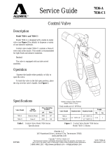
Inowing medium
If VEGACAP is mounted in the lling stream, unwanted false measure-
ment signals can be generated. For this reason, mount VEGACAP at a
position in the vessel where no disturbances, e.g. from lling openings,
agitators, etc., can occur.
This applies particularly to instrument versions with a longer probe.
Fig.14:Inowingmedium
Pressure/Vacuum
The process tting must be sealed if there is gauge or low pressure in
the vessel. Check if the seal material is resistant against the measured
product and the process temperature.
Insulating measures in metal vessels such as e.g. covering the thread
with teon tape can interrupt the necessary electrical connection to the
vessel. Ground the probe on the vessel.
Length of the level detection probe
Keep in mind when ordering the instrument that when the switching
point is reached the probe must be suciently immersed according to
the desired lling level, and that the depth of immersion depends on the
electrical properties (dielectric value) of the medium. An electrode for
level detection in oil (dielectric value ~2) requires a considerably deeper
immersion than one used in water (dielectric value ~81).
As a rule:
Non-conductive products > 50 mm
Conductive products > 30 mm
Lateral load
Make sure that the probe is not subjected to strong lateral forces. Mount
the probe at a position in the vessel where no interfering inuence, e.g.
from agitators, lling opening etc. can occur. This applies particularly to
very long rod and cable probes.
Product movement
Mount the probe in such a way that the probe cannot touch the vessel
wall and that the screening tube cannot be bent or broken.
Metal vessel
Make sure that the mechanical connection of the probe to the vessel is
electrically conductive to ensure sucient grounding.
Use conductive seals such as e.g. copper, lead etc.
Insulating measures such as e.g. covering the thread with teon tape can
interrupt the necessary electrical connection. If this is necessary, use the
ground terminal on the housing to connect the instrument with the vessel.
Non-conductive vessels
In non-conductive vessels, e.g. plastic tanks, the second pole of the
capacitor must be provided separately. Use a double rod electrode.
When using a standard probe, this can be e.g. the metal supporting
structure of the vessel.
It might be necessary to attach a suitable grounding surface. Attach a
very wide grounding surface outside on the vessel wall, e.g. wire textile
laminated into the vessel wall or a metal foil glued to the outside of the
vessel.
Connect the grounding surface to the ground terminal on the housing.
Rod probes
Install rod probes in such a way that the probe projects freely into the
vessel. When the instrument is mounted in a tube or socket, buildup can
form which impairs the measurement. This applies mainly to adhesive
products.
Inuencing factors
In practice, the dielectric value is subject to certain uctuations. The fol-
lowing factors can inuence of the capacitive measuring principle:
Concentration (mixing ratio of the product - provided it is not conduc-
tive)
Temperature
Conductivity (below 50 µS/cm)
The more constant the above mentioned factors, the better the condi-
tions for capacitive measurement. Changes in the conditions are gener-
ally not critical in products with high dielectric value.
If a very precise switching point is required, or if the the product changes
or has a low dielectric value, we recommend lateral mounting - a horizon-
tally mounted rod gets covered quickly over its entire length and has a
much more reliable switching function.
8
Mounting instructions
Capacitive
29983-EN-160930
You can either mount a standard measuring probe laterally or use an
angled measuring probe.
Operating temperatures
If the housing is subject to high ambient temperatures, you have to either
use a temperature adapter or disconnect the electronics from the probe
and install it in a separate housing at a cooler place.
Make sure that the probe is not covered by an existing vessel insulation.
The temperature ranges of the probes are listed in chapter "Technical
data".
Dielectric constant
In products with low dielectric value and slight level changes you should
try to increase the capacitance change. If the dielectric value is less than
1.5, special measures are necessary to ensure that the level is detected
reliably. E.g. additional surfaces can be attached or a screening tube
used with high sockets, etc.
For applications with high sockets and products with low dielectric value
you can compensate the strong inuence of the metal socket with a
concentric tube.
Electrically conductive products react like products with very high dielec-
tric value.
A detailed list with dielectric values is available on our homepage under
"Services - Downloads- Lists of measured products".
Corrosive, abrasive products
Various isolating materials are available for very corrosive or abrasive
products. If metal is not chemically resistant to the medium, use a plated
ange.
Protective cover
To protect the sensor against pollution and strong heat due to the sun,
you can snap a weather protective cover onto the sensor housing.
Fig.15:Weatherprotectioncoverindierentversions
9
Electrical connection
Capacitive
29983-EN-160930
5 Electrical connection
5.1 Preparing the connection
Note safety instructions
Always keep in mind the following safety instructions:
Connect only in the complete absence of line voltage
Take note of safety instructions for Ex applications
In hazardous areas you must take note of the respective regula-
tions, conformity and type approval certicates of the sensors and
power supply units.
Select power supply
Connect the operating voltage according to the following diagrams. Oscil-
lators with relay output and contactless electronic switch are designed
in protection class 1. To maintain this protection class, it is absolutely
necessary that the ground conductor be connected to the internal ground
terminal. Take note of the general installation regulations. As a rule, con-
nect VEGACAP to vessel ground (PA), or in case of plastic vessels, to
the next ground potential. On the side of the housing there is a ground
terminal between the cable entries. This connection serves to drain o
electrostatic charges. In Ex applications, the installation regulations for
hazardous areas must be given priority.
The data for power supply are specied in chapter "Technical data".
Select connection cable
VEGACAP is connected with standard cable with round cross section. An
outer cable diameter of 5 … 9 mm (0.2 … 0.35 in) ensures the seal eect
of the cable gland.
If cable with a dierent diameter or wire cross section is used, exchange
the seal or use an appropriate cable connection.
In hazardous areas, use only approved cable connections for
VEGACAP.
Select connection cable for Ex applications
Take note of the corresponding installation regulations for Ex
applications.
5.2 Wiring plan
Relay output
We recommend connecting VEGACAP in such a way that the switch-
ing circuit is open when there is a level signal, line break or failure (safe
state).
The relays are always shown in non-operative condition.
3
2 1
Fig. 16: Wiring plan, single chamber housing
1 Relay output
2 Relay output
3 Voltage supply
Transistor output
We recommend connecting VEGACAP in such a way that the switch-
ing circuit is open when there is a level signal, line break or failure (safe
state).
The instrument is used to control relays, contactors, magnet valves,
warning lights, horns as well as PLC inputs.
1
Fig. 17: Wiring plan, single chamber housing
1 Voltage supply
+ -
+-
1234
Fig. 18: NPN action
+-
+ -
1234
Fig. 19: PNP action
Contactless electronic switch
We recommend connecting VEGACAP in such a way that the switch-
ing circuit is open when there is a level signal, line break or failure (safe
state).
The contactless electronic switch is always shown in non-operative
condition.
The instrument is used for direct control of relays, contactors, magnet
valves, warning lights, horns etc. It must not be operated without an inter-
mediately connected load, because the electronics would be destroyed
if connected directly to the mains. It is not suitable for connection to low
voltage PLC inputs.
Domestic current is temporarily lowered below 1 mA after switching o
the load so that contactors, whose holding current is lower than the con-
stant domestic current of the electronics, are reliably switched o.
When VEGACAP is used as part of an overll protection system accord-
ing to WHG, also note the regulations of the general type approval.
10
Electrical connection
Capacitive
29983-EN-160930
1
Fig. 20: Wiring plan, single chamber housing
1 Voltage supply
Two-wire output
We recommend connecting VEGACAP in such a way that the switch-
ing circuit is open when there is a level signal, line break or failure (safe
state).
For connection to a VEGATOR signal conditioning instrument dto. Ex.
The sensor is powered by the connected VEGATOR signal conditioning
instrument. Further information is available in chapter "Technical data",
"Ex-technical data" are available in the supplied "Safety information
manual".
The wiring example is applicable for all suitable signal conditioning
instruments.
Take note of the operating instructions manual of the signal conditioning
instrument. Suitable signal conditioning instruments are listed in chapter
"Technical data".
1
Fig. 21: Wiring plan, single chamber housing
1 Voltage supply
11
Adjustment
Capacitive
29983-EN-160930
6 Adjustment
6.1 Adjustment, general
4
5
6
2
1
3
Fig. 22: Adjustment elements electronics module, e.g. relay output (CP60R)
1 Potentiometer for switching point adaptation (not with two-wire electronics)
2 Range switch
3 DIL switch for mode adjustment (not with two-wire electronics)
4 Ground terminal
5 Connection terminals
6 Control lamp
Switching point adaptation (1)
By using the potentiometer you can adapt the switching point of
VEGACAP to the medium.
With two-wire electronics the switching point is adjusted on the signal
conditioning instrument. For that reason there is no potentiometer.
Range switch (2)
Select the capacitance range of the probe with the mode switch.
With the potentiometer (1) and the mode switch (2) you can change the
switching point of the probe or adapt the sensitivity of the probe to the
electrical properties of the product and the conditions in the vessel.
This is necessary that the point level switch can for example also detect
products with very low or very high dielectric constant reliably.
Capacitance range
Range 1: 0 … 20 pF (sensitive)
Range 2: 0 … 85 pF
Range 3: 0 … 450 pF (insensitive)
Examples of dielectric values: air = 1, oil = 2, acetone = 20, water = 81
etc.
Turn the potentiometer (1) anticlockwise to make the probe more sensi-
tive.
Mode adjustment (3)
With the mode adjustment (min./max.) you can change the switching
condition of the output. You can set the required mode (max. - max. de-
tection or overow protection, min. - min. detection or dry run protection).
With two-wire electronics the mode is selected on the signal conditioning
instrument. For that reason there is no mode switch.
LED display (6)
Diode for indication of the switching status (with plastic housing visible
from outside).
12
Dimensions
Capacitive
29983-EN-160930
7 Dimensions
Housing
32
1
4
~ 69 mm
(2.72")
ø 79 mm
(3.11")
117 mm (4.61")
M20x1,5/
½ NPT
~ 59 mm
(2.32")
ø 80 mm
(3.15")
112 mm (4.41")
M20x1,5/
½ NPT
~ 69 mm
(2.72")
ø 79 mm
(3.03")
112 mm (4.41")
M20x1,5/
½ NPT
~ 116 mm (4.57")
ø 86 mm (3.39")
116 mm (4.57")
M20x1,5
M20x1,5/
½ NPT
Fig. 23: Housing versions
1 Plastic housing
2 Stainless steel housing
3 Stainless steel housing - precision casting
3 Aluminium housing
VEGACAP 62
ø 16 mm
(0.63")
100 mm
(3.94")
12 mm
(0.47")
L
G ¾, G 1, G 1½
56 mm
(2.21")
22 mm
(0.87”)
Fig. 24: VEGACAP 62 - threaded version
L Sensor length, see chapter "Technical data"
VEGACAP 63
ø 16mm
(0.63")
L
G¾, G 1, G 1½
56 mm
(2.21")
22 mm
(0.86")
Fig. 25: VEGACAP 63 - threaded version
L Sensor length, see chapter "Technical data"
VEGACAP 64
ø 16mm
(0.63")
L
G¾, G 1, G 1½
56 mm
(2.21")
22 mm
(0.86")
Fig. 26: VEGACAP 64 - threaded version
L Sensor length, see chapter "Technical data"
VEGACAP 66
177 mm
(7.87")
ø 8 mm
(0.32")
L
G 1
G 1½
56 mm
(2.21")
ø 30 mm
(1.18")
22 mm
(0.87")
Fig. 27: VEGACAP 66 - threaded version
L Sensor length, see chapter "Technical data"
13
Dimensions
Capacitive
29983-EN-160930
VEGACAP 69
ø 14 mm
(0.55")
47 mm
(1.85")
L
25 mm
(0.98")
87,5 mm
(3.45")
Fig. 28: VEGACAP 69
L Sensor length, see chapter "Technical data"
14
Notes
Capacitive
29983-EN-160930
15
Notes
Capacitive
29983-EN-160930
VEGA Grieshaber KG
Am Hohenstein 113
77761 Schiltach
Germany
29983-EN-160930
All statements concerning scope of delivery, application, practical use and operating conditions of the sensors and processing systems correspond to the information
available at the time of printing.
Subject to change without prior notice
© VEGA Grieshaber KG, Schiltach/Germany 2016
Phone +49 7836 50-0
Fax +49 7836 50-201
www.vega.com
  • Page 1 1
  • Page 2 2
  • Page 3 3
  • Page 4 4
  • Page 5 5
  • Page 6 6
  • Page 7 7
  • Page 8 8
  • Page 9 9
  • Page 10 10
  • Page 11 11
  • Page 12 12
  • Page 13 13
  • Page 14 14
  • Page 15 15
  • Page 16 16

Vega VEGACAP 63 Product information

Type
Product information
This manual is also suitable for

Ask a question and I''ll find the answer in the document

Finding information in a document is now easier with AI