ALTERNATOR INPUT
++
25A DCDC & MPPT
SOLAR CHARGER
50A MAX
COMBINED
+
+ +
+
+
+
+
2X IN/OUT POWER CONNECTOR
4X IN/OUT POWER CONNECTOR
DCDC CHARGER GUIDE
WARNING!
SOLAR INPUT
(UNREGULATED 9-23V DC)
DO NOT SHORT CIRCUIT (UNFUSED)
LiFe PO4 POWER STATION
L1
HIGH POWER CONNECTOR
100A MAX
SOLAR LED STATUS
ALTERNATOR LED BATTERY STATUS WITH IGNITION WIRE CONNECTED
ALTERNATOR LED BATTERY STATUS
Alternator voltage 12V Alternator voltage 24V Alternator LED
Solar LED
Status
Alternator voltage 12V Alternator voltage 24V Alternator LED Status
Status
0-8.9 Volts
9-12.6 Volts
12.7-13.1 Volts
13.2 Volts
12-17.9 Volts
18-25.2 Volts
25.3-26.3 Volts
26.4 Volts
OFF
Flash 1 sec on 5 sec off
Flash 1 sec on 1 sec off
Solid on
Under operating voltage
Under cut-out voltage
Under cut-in voltage
Cut-in voltage reached, charging will
start after 30 second delay
0-8.9 Volts
9-11.6 Volts
11.7-12.1 Volts
12.2 Volts
12-17.9 Volts
18-23.2 Volts
23.3-24.3 Volts
24.4 Volts
OFF
Flash 1 sec on 5 sec off
Flash 1 sec on 1 sec off
Solid on
Under operating voltage
Under cut-out voltage
Under cut-in voltage
0-8.9 Volts
Unregulated 9-23V DC
OFF
Solid on
Under cut-in voltage
Cut-in voltage reached, charging will begin after 10 sec
delay (please note alternator has priority over solar)
Cut-in voltage reached, charging will
start after 30 second delay
23V + Solar LED is Off Solar Input Voltage Exceeded
Solar voltage
MASTER SWITCH
CIG SOCKET
10A MAX
CIG SOCKET
10A MAX
2 X USB
QC3.0 & 2.4AMP
(5A OUT MAX)
2 X USB
QC3.0 & 2.4AMP
(5A OUT MAX)
LITHIUM LIFEPO4 COLOUR LCD screen
iNTEGRATED WITH
CHARGER
BATTERY BMS
INFORMATION
BUILT-IN CIRCUIT
BREAKERS
multiple power
outlets
Automatic Starter
Battery Isolation
USB QC3 QUICK
CHARGING
MPPT
LITHIUM BATTERY
FAULT ALARMS
Maximum Continuous Output Current: 100A
Peak Discharge Current: 110A for 7 Seconds
Discharge Temperature Range: -20-60°C
Max Charge Voltage: 14.6V
Recommended Continuous Charge Current: 40A
Charging Temperature Range: 0-45°C
SCAN QR CODE TO GET MORE INFO
BATTERY BOX DISPLAY A. MENU
B. ON/OFF
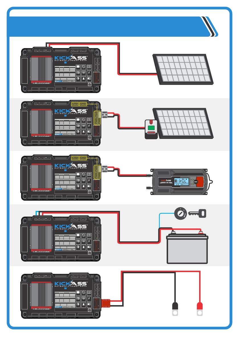
TYPICAL DIAGRAMS
REGULATED SOLAR PANEL
POWER
CHARGING/
FAULT
22A
SMART
CHARGER
CO M P AT I B I L I T Y
LEAD ACID GEL AGM LITHIUM
AC CHARGER
UNREGULATED SOLAR PANEL 23V MAX
VEHICLE
BATTERY
VEHICLE IGNITION
+-
plug-in to any of
these sockets
plug-in to any of
these sockets
ALTERNATOR INPUT
++
25A DCDC & MPPT
SOLAR CHARGER
50A MAX
COMBINED
+
+ +
+
+
+
+
2X IN/OUT POWER CONNECTOR
4X IN/OUT POWER CONNECTOR
DCDC CHARGER GUIDE
WARNING!
SOLAR INPUT
(UNREGULATED 9-23V DC)
DO NOT SHORT CIRCUIT (UNFUSED)
LiFe PO4 POWER STATION
L1
HIGH POWER CONNECTOR
100A MAX
SOLAR LED STATUS
ALTERNATOR LED BATTERY STATUS WITH IGNITION WIRE CONNECTED
ALTERNATOR LED BATTERY STATUS
Alternator voltage 12V Alternator voltage 24V Alternator LED
Solar LED
Status
Alternator voltage 12V Alternator voltage 24V Alternator LED Status
Status
0-8.9 Volts
9-12.6 Volts
12.7-13.1 Volts
13.2 Volts
12-17.9 Volts
18-25.2 Volts
25.3-26.3 Volts
26.4 Volts
OFF
Flash 1 sec on 5 sec off
Flash 1 sec on 1 sec off
Solid on
Under operating voltage
Under cut-out voltage
Under cut-in voltage
Cut-in voltage reached, charging will
start after 30 second delay
0-8.9 Volts
9-11.6 Volts
11.7-12.1 Volts
12.2 Volts
12-17.9 Volts
18-23.2 Volts
23.3-24.3 Volts
24.4 Volts
OFF
Flash 1 sec on 5 sec off
Flash 1 sec on 1 sec off
Solid on
Under operating voltage
Under cut-out voltage
Under cut-in voltage
0-8.9 Volts
Unregulated 9-23V DC
OFF
Solid on
Under cut-in voltage
Cut-in voltage reached, charging will begin after 10 sec
delay (please note alternator has priority over solar)
Cut-in voltage reached, charging will
start after 30 second delay
23V + Solar LED is Off Solar Input Voltage Exceeded
Solar voltage
MASTER SWITCH
CIG SOCKET
10A MAX
CIG SOCKET
10A MAX
2 X USB
QC3.0 & 2.4AMP
(5A OUT MAX)
2 X USB
QC3.0 & 2.4AMP
(5A OUT MAX)
LITHIUM LIFEPO4 COLOUR LCD screen
iNTEGRATED WITH
CHARGER
BATTERY BMS
INFORMATION
BUILT-IN CIRCUIT
BREAKERS
multiple power
outlets
Automatic Starter
Battery Isolation
USB QC3 QUICK
CHARGING
MPPT
LITHIUM BATTERY
FAULT ALARMS
Maximum Continuous Output Current: 100A
Peak Discharge Current: 110A for 7 Seconds
Discharge Temperature Range: -20-60°C
Max Charge Voltage: 14.6V
Recommended Continuous Charge Current: 40A
Charging Temperature Range: 0-45°C
SCAN QR CODE TO GET MORE INFO
BATTERY BOX DISPLAY A. MENU
B. ON/OFF
INVERTER CONNECTION


