Page is loading ...

Installation Manual for VMAC
System A70G120
2013-2011 Ford F250-F550 6.7L Diesel
General Information..................................................................... 4
Before You Start ....................................................................... 4
Additional Requirements .......................................................... 5
Part 1: Warranty and System ID ................................................. 6
Part 2: Preparing for Installation ............................................... 8
Part 3: Installing the Compressor Components ...................... 9
Part 4: Installing the Discharge Check Valve .......................... 11
4.1 Installing the Discharge Check Valve ................................. 11
Part 5: Installing the Control Components .............................. 12
5.1 Removing the Control Components ................................... 13
5.2 Routing the Wiring .............................................................. 13
5.3 Installing the components ................................................... 14
5.4 Connecting the In-cab Wiring ............................................. 19
5.5 Completing and Testing the Installation ............................. 22
Part 6: Finishing the Installation ................................................ 26
6.1 Before Starting the Engine Checklist.................................. 26
6.2 Safety Test ......................................................................... 26
6.3 Setup, Performance Testing and Adjustments ................... 29
6.4 Auxiliary Air Receiver ......................................................... 30
Accessory Products from VMAC ............................................... 31

VMAC – Vehicle Mounted Air Compressors
Toll Free: 1-888-241-2289
Fax: 1-250-740-3201
2
!
Document #1930203
Installation Manual for VMAC System A70G120
2013-2011 Ford F250-F550 6.7L Diesel
Changes and Revisions
Version
Revision Details
Revised by/date
Approved
Implemented
A
ECN 13-021 Eng. Release
SDM 15Feb2013
RD/SM 15 Feb 2013
15 Feb 2013
Important Information
This symbol is used to call your attention to instructions
concerning your personal safety. Watch for this symbol; it
points out important safety precautions, it means “attention,
become alert! Your personal safety is involved. Read the
message that follows and be alert to the possibility of personal
injury or death. Be alert; your safety is involved. While it is
impossible to warn about every conceivable hazard, let good
common sense be your guide.
This symbol is used to call your attention to additional
instructions or special emphasis on a specific procedure.
The information in this manual is intended for certified VMAC
installers who have been trained in installation procedures and for
people with mechanical trade certification who have the tools and
equipment to properly and safely perform the installation. Do not
attempt this installation if you do not have the appropriate
mechanical training, knowledge and experience.
Follow all safety precautions for under hood mechanical work. Any
grinding, bending or restructuring operations for correct fit in modified
trucks must follow standard shop practices.
All hoses, tubes, and wires that are rerouted or shifted
during installation must be secure so that they do not
contact excessively hot areas or sharp edges. Where
possible, use rubber coated P-clips. Follow the routing
suggestions in this manual and cover all hoses with the
supplied plastic loom.
These instructions are a general guide for installing this system on
standard production trucks and do not contain information for
installation on non-standard trucks. This system may not fit special
order models or those which have had other changes without
additional modifications. If you have difficulty with the installation,
contact VMAC.
!

VMAC – Vehicle Mounted Air Compressors
Toll Free: 1-888-241-2289
Fax: 1-250-740-3201
3
The VMAC warranty form is located at the back of this manual. This
warranty form must be completed and mailed or faxed to VMAC at
the time of installation for any subsequent warranty claim to be
considered valid.
To order parts, contact your VMAC dealer. Your dealer will ask for
the VMAC serial number, part number, description and quantity. To
locate your nearest dealer, call 1-888-241-2289.
Copyright 2013
All trademarks used in this manual are the property of the respective copyright holder.
The contents of this manual may not be reproduced in any form without the express
written permission of VMAC, 1333 Kipp Road, Nanaimo, BC V9X 1R3.
Printed in Canada

VMAC – Vehicle Mounted Air Compressors
Toll Free: 1-888-241-2289
Fax: 1-250-740-3201
4
General Information
Before You Start
Read this manual before attempting installation so that you can
familiarize yourself with the components and how they fit on the
truck. Identify variations for different model years and different
situations that are listed in the manual. Open the package, unpack
the components and identify them.
All fasteners must be torqued to specifications. Use manufacturers
torque values for OEM fasteners. Apply Loctite 242 or equivalent on
all engine-mounted fasteners. Torque values are with Loctite applied
unless otherwise specified.
STANDARD GRADE 8 NATIONAL COARSE THREAD
Size
1/4
5/16
3/8
7/16
1/2
9/16
5/8
¾
Foot-pounds (ft-lb)
9
18
35
55
80
110
170
280
Newton meter (N•m)
12
24
47
74
108
149
230
379
STANDARD GRADE 8 NATIONAL FINE THREAD
Size
3/8
7/16
1/2
5/8
¾
Foot-pounds (ft-lb)
40
60
90
180
320
Newton meter (N•m)
54
81
122
244
434
METRIC CLASS 10.9
Size
M8
M10
M12
M14
M16
Foot-pounds (ft-lb)
19
41
69
104
174
Newton meter (N•m)
25
55
93
141
236

VMAC – Vehicle Mounted Air Compressors
Toll Free: 1-888-241-2289
Fax: 1-250-740-3201
5
!
Additional Requirements
Special Tools
None required for this kit.
Hose Information
Depending on other installed equipment, it might be
necessary to move the air/oil separation tank from its
intended location. The hoses used in VMAC
compressor systems have a specific inner liner that is
compatible with our compressor oil. Use of hoses other
than those supplied or recommended by VMAC may
cause compressor damage and may void your
warranty. Please contact VMAC for replacement hoses
and further information.

VMAC – Vehicle Mounted Air Compressors
Toll Free: 1-888-241-2289
Fax: 1-250-740-3201
6
Part 1: Warranty and System ID
□ Complete the warranty form. The VMAC warranty form is located
at the back of this manual. This warranty form must be
completed and mailed or faxed to VMAC at the time of
installation for any subsequent warranty claim to be considered
valid.
System Identification and Operating Instructions
The System Identification Number Plate must be attached to the
vehicle at the time of installation. This plate provides information that
allows VMAC to assist in customer inquiries and the ordering of
parts.
□ Locate the original V900120 system id plate. It should be in the
top of the cross member in front of the OEM air filter box. Mark
and drill two 7/64-inch holes as close to this plate as possible.
Secure the A70G120 plate with supplied self- tapping screws
□ If not already attached, clean cross member beside the number
plate and stick the VMAC belt routing diagram to the cross
member.
□ Apply battery warning label to driver side of primary cooling
reservoir.
□ As part of the installation process, ensure that the safety and
operational instruction decal is affixed in an obvious location so
that it can be seen by vehicle operators. A good spot for this is
usually on the inside of the door or on the panel underneath the
steering wheel. (Figure 1.1).

VMAC – Vehicle Mounted Air Compressors
Toll Free: 1-888-241-2289
Fax: 1-250-740-3201
7
Figure 1.1

VMAC – Vehicle Mounted Air Compressors
Toll Free: 1-888-241-2289
Fax: 1-250-740-3201
8
Part 2: Preparing for Installation
Preparation for installation is very important. Missing an item can
cause problems in the installation or even damage to components.
Check off each item as it is completed so that you do not miss any
preparation steps.
Ensure that you have filled out the VMAC Warranty
Registration. Install the System Identification Number
Plate and Operational Instruction Decal. (Please see
Part 1 for details).
Always discharge all air from the system before
servicing the compressor or its components.
□ Disconnect the batteries, (both driver and the one relocated from
the passenger side).
□ Loosen the hose clamps on the engine intake tube at the
silicone elbow and the bellows on the engine. Remove the
intake tube. Cover both openings.
It is very important to tape or cover the openings in the
engine to ensure that nothing can enter the engine as this
may cause severe damage to the internal parts or failure
of the engine.
!

VMAC – Vehicle Mounted Air Compressors
Toll Free: 1-888-241-2289
Fax: 1-250-740-3201
9
Part 3: Installing the
Compressor Components
□ Thoroughly clean the inlet valve and top of the compressor.
□ Disconnect the 3/16” & 1/4" tubes from the inlet valve fittings.
□ Locate the pressure sensor on the passenger side firewall.
□ Remove the bolt retaining the P-clip and remove the assembly.
Replace the bolt.
□ Remove the two bolts, washers and nylock nuts joining the two
brace brackets between the inlet valve and the engine block.
Retain the fasteners for later use.
□ Remove the four bolts and the upper brace bracket holding the
inlet to the compressor. Retain the fasteners and bracket and
make note of the location of the different lengths as removed.
(Figure 3.1)
□ Remove the inlet valve.
□ Immediately cover the opening in the compressor to prevent any
contaminates from entering the rotor housing.
It is very important to tape or cover the opening in the top
of the compressor to ensure that nothing can enter the
compressor housing as this may cause severe damage to
the internal parts or failure of the compressor.
□ Clean and inspect the O-ring for damage, replace if necessary.
□ With O-ring in place, install the new inlet valve, upper brace
bracket and the four bolts in the same locations as removed
from. Finger tight only.

VMAC – Vehicle Mounted Air Compressors
Toll Free: 1-888-241-2289
Fax: 1-250-740-3201
10
□ Before torquing inlet valve bolts, install and snug bolts holding
inlet brace together while holding bracket down tight on inlet
valve. Then torque the four inlet bolts to specifications, followed
by tightening the brace bolts.
Longest Bolts
Shortest Bolt
Figure 3.1 (Inlet not exactly as shown)
Never use an impact wrench to install inlet bolts.
The torque spec for inlet bolts is 19 ft. lbs.
□ Reconnect the 3/16” and 1/4” lines onto the inlet valve.
!

VMAC – Vehicle Mounted Air Compressors
Toll Free: 1-888-241-2289
Fax: 1-250-740-3201
11
Part 4: Installing the Discharge
Check Valve
4.1 Installing the Discharge Check Valve
Discharge all air from any reservoir tanks installed in
the system.
□ Clean the discharge hose and fitting at the back of the tank on
the passenger side frame rail.
□ Disconnect the discharge hose.
□ Remove the discharge fitting from the back end of the tank.
□ If a check valve is installed between the VR tank and any
reservoir tanks, remove it from the system.
□ Install the discharge check valve assembly supplied. Ensure
that the pressure sensor is at the top.
□ Install the discharge fitting into the end of the check valve
assembly.
□ Reconnect the discharge hose to the check valve assembly
fitting.
It is strongly recommended that a reservoir tank of a
minimum of 5 gal. is installed to best take advantage of the
start/stop features of the VR70G system.
!

VMAC – Vehicle Mounted Air Compressors
Toll Free: 1-888-241-2289
Fax: 1-250-740-3201
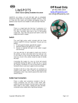
12
Part 5: Installing the Control
Components
Figure 5.1
CONTROL BOX
RELAYS
START
HOT
12V
STOP
PARK ONLY, BLU
To OEM SEIC blue wire w/
grey stripe CLS05
DISPLAY
BOX
16
RED +
BLK -
3 Amp
Fuse
4
4
Cut OEM wire
Inside steering column
Splice/solder joints
YEL
BLU
ORG
BLU
GRN-RED or BLU-RED
BLU-WHT
Both go to OEM Ignition Switch Harness
To Hood Sw. 2 Pin
Conn – GRY & BLK
To Clutch Bullet Conn - WHT
DIGITAL GND,
GRN-YEL To pin 3
Purple w/ green stripe
To AOST 3 pin BLK
pressure connector
To Beacon 2 Pin
Conn - GRY & RED
4
To Buzzer Ring
Conn - BLK & RED
To Inlet 2 Pin
Conn - BRN & RED
To Temp. Sensor
4 pin GRN Conn
OEM Connector
to accelerator
pedal
REMOTE ON,
YEL
Connect to
accelerator
pedal
GROUND, GRN-YEL
TACH, WHT
To OEM SEIC blue wire CE913
THROTTLE
CONTROLLER
PARK BRAKE, BRN
To OEM SEIC white wire w/ purple stripe
CMC25
ORG
IGN SW 12V, RED
To OEM SEIC yellow wire w/ orange stripe on early
builds or white wire w/ blue stripe on later builds
CDC64
Firewall
Diode
IGNITION CONNECTOR
IN STEERING WHEEL
4 7
YEL
BLU
ORG

VMAC – Vehicle Mounted Air Compressors
Toll Free: 1-888-241-2289
Fax: 1-250-740-3201
13
5.1 Removing the Control Components
□ Disconnect the White four-wire interface connector from the
control box.
□ Disconnect the Green 4-pin connector going to the compressor
from the control box.
□ Remove the control box.
□ Disconnect the following from the throttle controller:
Red wire bullet connector.
Green wire ring connector.
Two accelerator pedal connectors.
Black 3 pin connector going to the inlet valve.
Cut the blue park-only & white CTO wires (mark both for
later use).
□ Disconnect the white wire bullet connector from the clutch.
□ Disconnect the interface cable’s green wire ring connector.
□ Remove the interface cable by cutting its red (IGN SW 12V) and
black (Park Brake) wires. (mark both for later use).
5.2 Routing the Wiring
□ Determine suitable installation locations for the Buzzer and
Beacon modules.
The Buzzer should be located such that it is audible to
individuals around the vehicle.
The Beacon should be located such that it is visible to
individuals around the vehicle.
□ Estimate the length to be added to both the Buzzer and Beacon
wires.
□ Extend the blunt-cut red and black BUZZER wiring on the control
box harness with 18AWG wiring. Solder and seal.
□ Extend the blunt-cut grey and red BEACON wiring on the control
box harness with 18AWG wiring. Solder and seal.

VMAC – Vehicle Mounted Air Compressors
Toll Free: 1-888-241-2289
Fax: 1-250-740-3201
14
□ Cut an opening in the firewall plug or use an existing opening,
and route harness wires from the cab to the engine bay for the
following:
Hood switch
Inlet valve solenoid
Pressure sensor
Compressor temperature sensor
Clutch
Buzzer
Beacon
□ Route these wires to their destinations. One suitable way is:
Route the Beacon and Buzzer wires to their installation
locations.
Route the remaining wires along the perimeter of the engine
bay to the front of the truck.
The hood switch connector rests near the driver’s side
headlight
The remaining wiring follows the radiator cooling lines across
the radiator towards the compressor
The inlet valve solenoid, clutch, and compressor
temperature connectors rest near the compressor.
The remaining pressure sensor cable can go down along
with the pressure line until it reaches the chassis. Then run
along the chassis towards the rear of the truck to the location
of the Discharge Check Valve at the back of the tank.
□ Crimp the ring terminals provided to the end of the Buzzer wires.
□ Solder and seal the pigtail provided in the AUS Electrical Pack to
the end of the Beacon wires placed through firewall.
5.3 Installing the components
5.3.1 Control Box Mount
□ Fasten the control box to the control mount bracket using screws
provided in its fastener pack.
□ Fasten the relay sockets onto the mount bracket using remaining
screws in the fastener pack.

VMAC – Vehicle Mounted Air Compressors
Toll Free: 1-888-241-2289
Fax: 1-250-740-3201
15
□ Install relays into the relay-sockets.
Verify the terminals in the relay-sockets did not get
pushed loose from the relay-sockets during relay
installation.
□ Install the control box wiring harness’ three rectangular
connectors into their respective mates on the control box.
□ Fasten the heat-shrunk diode with a nylon-tie to either the fuse
holder or the back side of the narrow column on the control
mount. The diode assembly can be identified by its short orange
and long red wires coming out of heat-shrunk tubing.
□ Find the two unused M8 vertical studs (2-3/4” apart) located
inside the cab above the firewall plug.
□ Install control box mounting bracket as shown in Figure 5.2.
Figure 5.2
HOT 12V
RELAY
EXISTING FORD
STUDS ABOVE
KICKER PANEL
STOP
RELAY
START
RELAY

VMAC – Vehicle Mounted Air Compressors
Toll Free: 1-888-241-2289
Fax: 1-250-740-3201
16
Figure 5.3
5.3.2 VR Throttle Controller
□ Install the Throttle Controller underneath the dash with nylon-
ties.
□ Route both of its two 6-pin connectors to the foot pedal.
□ Connect the 4-pin connector with the mating connector on the
wiring harness coming from the Control Box.
Ensure wiring and in-cab installed electronics keep away
from, and do not interfere with, the operation of the park
brake mechanism, brake & accelerator pedals, and
steering column.
5.3.3 Hood Switch
Blue w/Pink
OEM Wire
Grey - VMAC Wire To Be Added
Shrink Sleeve
Soldered Joint
Figure 5.4

VMAC – Vehicle Mounted Air Compressors
Toll Free: 1-888-241-2289
Fax: 1-250-740-3201
17
□ If the vehicle comes equipped with a hood switch, splice and
seal the OEM blue w/pink hood switch wire with VMAC’s grey
hood-switch wire, See Figure 5.4. Ensure VMAC’s black hood-
switch connector wire is left unexposed, as it is at 12V. Skip to
section 5.3.4
□ If the vehicle doesn’t come equipped with hood switch, using the
provided screw, install hood switch in a pre-existing hole in the
engine bay, near the driver’s headlight. See Figure 5.5
Figure 5.5
□ Visually verify the switch is suitably installed such that it’s
actuated when the hood is closed.
□ Connect the hood switch’s connector to its mating connector on
the main wiring harness in the engine bay.
5.3.4 Compressor Connections
□ Connect the Inlet Valve Solenoid on the VR70 Compressor
Assembly to its mating connector with red and brown wires on
the wiring harness.
HOOD SWITCH
FWD

VMAC – Vehicle Mounted Air Compressors
Toll Free: 1-888-241-2289
Fax: 1-250-740-3201
18
□ Connect the Clutch on the VR70 Compressor Assembly to the
mating bullet connector with white wire on the wiring harness.
□ Connect the Compressor Temperature Sensor on the VR70
Compressor Assembly to its mating 7 pin (4 wires) connector on
the wiring harness.
5.3.5 Pressure Sensor
□ Connect the Pressure Sensor on the Discharge Check Valve to
the mating connector on the wiring harness.
5.3.6 Beacon and Buzzer Modules
Verify the Beacon and Buzzer installation locations make
them visible and audible to individuals around the vehicle.
□ Install the Beacon and Buzzer in suitable locations.
□ Connect the Beacon with the mating connector on wiring
harness.
□ Connect the Buzzer wires (with ring terminals) routed earlier.
The red wire goes to positive on Buzzer, and black wire goes to
negative on Buzzer.
5.3.7 Display Box
□ Connect the Display Box to the 4-wire connector coming from
the control box.
□ Install the Display Box in a suitable location with provided
screws.
Mount the Display Box inside the cab or a cabinet
protected from extreme weather. The Display Box is
splash-proof, but not fully sealed. Ensure that it will not
get kicked or hit by tools and equipment.

VMAC – Vehicle Mounted Air Compressors
Toll Free: 1-888-241-2289
Fax: 1-250-740-3201
19
5.4 Connecting the In-cab Wiring
□ Unplug the OEM foot pedal connector from the foot pedal
assembly.
□ Find the purple-green wire attached to pin 3 on the truck
harness. If needed, pull back any cover on the cable going into
the dash to expose the wires.
Verify with a multi-meter that the resistance between pin 3
on truck harness and truck ground is close to 0 Ohms.
□ Remove insulation on the wire and solder it to the 60” long
green-yellow “DIGITAL GROUND” wire coming from Control
Box. Trim the green-yellow wire’s length as needed before
soldering and sealing.
□ Connect the Throttle Controller’s connector to the foot pedal
assembly.
□ Connect the Throttle Controller’s remaining connector to the
OEM harness for the foot pedal assembly.
□ Locate the blunt-cut OEM SEIC wire harness, on the driver’s
side just below the OBDII port (Figure 5.6). You will need to find
the following wires:
ignition-switched 12V OEM SEIC circuit CDC64 –
yellow wire with orange stripe on early builds
white wire with blue stripe on later builds
tachometer signal OEM SEIC circuit CE913 – blue wire
transmission park signal OEM SEIC circuit CLS05 – blue
with grey stripe (marked previously)
park brake switch OEM SEIC CMC25 – white wire with
purple stripe
These were all marked during the removal of the original
electrical components.

VMAC – Vehicle Mounted Air Compressors
Toll Free: 1-888-241-2289
Fax: 1-250-740-3201
20
HOOD
SEIC blunt-cut wires
bundle
Figure 5.6
□ Solder and seal the long red ‘KEY SWITCHED 12V’ wire
(coming from the shrink-wrapped diode) to the OEM SEIC circuit
CDC64 yellow with orange stripe wire on early builds, white with
blue stripe wire on later builds, at the blunt-cut harness.
□ Connect the ring terminal on the green-yellow ground wire
coming from the control box to any grounded bolt underneath the
dash.
□ Solder and seal the white ‘TACH’ wire coming from the control
box to the OEM SEIC circuit CE913 blue wire at the blunt-cut
harness.
□ Solder and seal the black ‘PARK BRAKE’ wire from the control
box to the OEM SIEC circuit CMC25 white wire with a purple
stripe at the blunt-cut harness
□ Solder and seal the long blue ‘PARK NEUTRAL’ wire coming
from the Throttle Controller to the transmission park signal found
earlier. This should be the OEM SEIC circuit CLS05 blue wire
with grey stripe in the blunt-cut bundle.
/