
SM-
SM-SM-
SM-195407
195407195407
195407-A
-A-A
-A
INSTRUCTION
INSTRUCTIONINSTRUCTION
INSTRUCTION
MANUAL
MANUALMANUAL
MANUAL
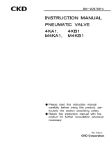
MINIATURE
MINIATUREMINIATURE
MINIATURE
SPEED
SPEEDSPEED
SPEED
CONTROL
CONTROLCONTROL
CONTROL VALVE
VALVE VALVE
VALVE
SC
SCSC
SC
―
――
―
―
――
―S,L,F,A
S,L,F,AS,L,F,A
S,L,F,A
●
Please read this instruction manual carefully
before using this product, particularly the
section describing safety.
●
Retain this instruction manual with the
product for further consultation whenever
necessary.
M
3
M5

[SM-195407-A]
―1―
Safety precautions
When designing and manufacturing a device using CKD products, the manufacturer is
obligated to manufacture a safe product by confirming safety of the system comprising the
following items:
Device mechanism
Pneumatic or water control circuit
Electric control that controls the above
It is important to select, use, handle, and maintain the product appropriately to ensure that
the CKD product is used safely.
Observe warnings and precautions to ensure device safety.
Check that device safety is ensured, and manufacture a safe device.
1
11
1.
..
.This product is designed and manufactured as a general industrial machine part.
This product is designed and manufactured as a general industrial machine part.This product is designed and manufactured as a general industrial machine part.
This product is designed and manufactured as a general industrial machine part.
It must be handled by someone having sufficient knowledge and experience.
It must be handled by someone having sufficient knowledge and experience. It must be handled by someone having sufficient knowledge and experience.
It must be handled by someone having sufficient knowledge and experience.
2
22
2.
..
.Use this product within its specifications.
Use this product within its specifications.Use this product within its specifications.
Use this product within its specifications.
This product cannot be used beyond its specifications. Additionally, the product must not
be modified or machined.
This product is intended for use in general industrial devices and parts. Use beyond such
conditions is not considered. Consult with CKD for details when using the product beyond
the unique specification range, outdoors, or in the following conditions or environments. In
any case, measures for safety shall be provided when the vavle malfunctions.
① Use for special applications requiring safety including nuclear energy, railroad, aviation,
ship, vehicle, medical equipment, equipment or applications coming into contact with
beverage or food, amusement equipment, emergency shutoff circuits, press machine,
brake circuits, or for safeguard.
② Use for applications where life or assets could be adversely affected, and special safety
measures are required.
3
33
3.
..
.Observe corporate standards and regulations, etc., related to the safety of device
Observe corporate standards and regulations, etc., related to the safety of device Observe corporate standards and regulations, etc., related to the safety of device
Observe corporate standards and regulations, etc., related to the safety of device
design and control, etc.
design and control, etc.design and control, etc.
design and control, etc.
ISO4414, JIS B 8370 (pneumatic system rules)
JFPS2008 (principles for pneumatic cylinder selection and use)
Including High Pressure Gas Maintenance Law, Occupational Safety and Sanitation
Laws, other safety rules, standards and regulations, etc.
4
44
4.
..
.Do not handle, pipe, or remove devices before confirming safety.
Do not handle, pipe, or remove devices before confirming safety.Do not handle, pipe, or remove devices before confirming safety.
Do not handle, pipe, or remove devices before confirming safety.
① Inspect and service the machine and devices after confirming safety of the entire system
related to this product.
② Note that there may be hot or charged sections even after operation is stopped.
③ When inspecting or servicing the device, turn off the energy source (air supply or water
supply), and turn off power to the facility. Release any compressed air from the system,
and pay enough attention to possible water leakage and leakage of electricity.
④ When starting or restarting a machine or device that incorporates pneumatic components,
make sure that system safety, such as pop-out prevention measures, is secured.
5
55
5.
..
.Observe warnings and cautions on the pages below to prevent accidents.
Observe warnings and cautions on the pages below to prevent accidents.Observe warnings and cautions on the pages below to prevent accidents.
Observe warnings and cautions on the pages below to prevent accidents.
WARNING
WARNINGWARNING
WARNING

[SM-195407-A]
-2-
■The safety cautions are ranked as "DANGER", "WARNING" and "CAUTION" in
■The safety cautions are ranked as "DANGER", "WARNING" and "CAUTION" in ■The safety cautions are ranked as "DANGER", "WARNING" and "CAUTION" in
■The safety cautions are ranked as "DANGER", "WARNING" and "CAUTION" in
this section.
this section.this section.
this section.
:
::
:When a dangerous situation may occur if handling is mistaken
leading to fatal or serious injuries, or when there is a high
degree of emergency to a warning.
:
::
:When a dangerous situation may occur if handling is mistaken
leading to fatal or serious injuries.
:
::
:When a dangerous situation may occur if handling is
mistaken leading to minor injuries or physical damage.
Note that some items described as "CAUTION" may lead to serious results
depending on the situation. In any case, important information that must be
observed is explained.
Precautions
Precautions Precautions
Precautions with regard to guarantee
with regard to guaranteewith regard to guarantee
with regard to guarantee
Guarantee period
Guarantee periodGuarantee period
Guarantee period
The guarantee period of our product shall be one (1) year after it is delivered to the place
specified by the customer.
Guarantee coverage
Guarantee coverageGuarantee coverage
Guarantee coverage
If any failure for which CKD CORPORATION is recognized to be responsible occurs within
the above warranty period, a substitute or necessary replacement parts shall be provided free
of charge, or the product shall be repaired free of charge at the plant of CKD
CORPORATION.
However, the guarantee excludes following cases:
① Defects resulting from operation under conditions beyond those stated in the catalogue or
specifications.
② Failure resulting from malfunction of the equipment and/or machine manufactured by
other companies.
③ Failure resulting from wrong use of the product.
④ Failure resulting from modification or repairing that CKD CORPORATION is not involved
in.
⑤ Failure resulting from causes that could not be foreseen by the technology available at the
time of delivery.
⑥ Failure resulting from disaster that CKD is not responsible of.
Guarantee stated here covers only the delivered products. Any other damage resulting from
failure of the delivered products is not covered by this guarantee.
Confirmation of product compatibility
Confirmation of product compatibilityConfirmation of product compatibility
Confirmation of product compatibility
Our customer shall be responsible of confirming compatibility of our product used in our
customer’s system, machinery or device.
DANGER
DANGERDANGER
DANGER
WARNING
WARNINGWARNING
WARNING
CAUTION
CAUTIONCAUTION
CAUTION

Feb.15.2012
―3―
INDEX
SC-M3・M5 series
Miniature speed control valve
Manual No. SM-195407-A
1.
PRODUCT
1.1
Specification
·································································································· 4
1.2
Flow characteristics
··············································································· 4
1.3
Dimensions/Internal structure
···················································· 5
1.4
Fundamental Circuit Diagram
····················································· 7
2.
OPERATION
··········································································································8
3.
SAFETY PRECAUTIONS
··········································································9
4.
INSTALLATION
4.1
Fluid
·················································································································· 10
4.2
Piping
··············································································································· 10
5.
MAINTENANCE
5.1
Trouble shooting
····················································································· 11
6.
HOW TO ORDER
··························································································· 11

[SM-195407-A]
-4-
1. PRODUCT
1.1 Specification
Model
Descriptions
SC-M3-S
SC-M3-L
SC-M3-F
SC-M3-A
SC-M5-S
SC-M5-L
SC-M5-F
SC-M5-A
Working fluid Compressed air
Max. working pressure MPa 0.7
Min. working pressure MPa 0.1
Withstanding pressure MPa 1.05
Fluid temperature ℃ 5 to 60(no freezing) Note 1
Ambient temperature ℃ 0 to 60 (no freezing)
Port size M3 M5
Product weight g 1.7 1.5 2.4 2.4 5.6[6]
4.8[5.2]
7.9[8.3]
8.5[8.9]
Applicable cylinder bore size mm φ2.5 to φ10 φ6 to φ25
Number of needle turn 10 10[14]
Flow
Note2
L/min.(ANR) 20 53
Free flow Effective sectional
area mm
2
0.3 0.8
Flow
Note2
L/min.(ANR) 16 47[6.7]
Controlled
flow Effective sectional
area mm
2
0.25 0.7[0.1]
Note 1:Freezing
Could occur by adiabatic expansion depending on air quality (dew point)
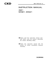
Note 2:Flow rate is the atmospheric pressure conversion value at pressure 0.5MPa
Value in [ ] is for fine speed type .
1.2 Flow characteristics
PRODUCT
1

[SM-195407-A]
―5―
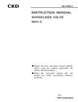
1.3 Dimensions/Internal structure
1)
Dimensions
●SC- -S(straight)
Model no.
A B C D
E
F
G
H
I J K
SC-M3-S
18.5(max21)
9 7.3
2.5
2.5
8
13
4.2
φ2.2
M3×0.5
5
SC-M5-S
25(max28.5)
13.5
11.2
4.2
3.5
12
19
6.5
φ3.2
M5×0.8
8
●SC- -L(elbow)
Model no.
A B C D
E
F G H
I J
SC-M3-L
20.3(max22.8)
10.8
7 1.9
2.5
6.5
9 5.7
φ2.2
M3×0.5
SC-M5-L
27.5(max31)
16
11.5
2.2
4.3
11.2
13.5
9
φ3.2
M5×0.8
●SC- -F(flat)
Model no.
A B C
D
E F
G
H
I
J・K
SC-M3-F
18.5(max21)
9 3.4
2.7
6.5
13
5
3
4.2
M3×0.5
SC-M5-F
25(max28.5)
13.5
5.1
4
10.5
20
8
3.5
6.5
M5×0.8
●SC- -A(adjustable)
Model no.
A B C
D
E F G H
I
J
SC-M3-A
18.5(max21)
9 3
3.2
8 14.5
M3×0.5
5
4.2
M3×0.5
SC-M5-A
25(max28.5)
13.5
3.5
4.5
12.5
22
M5×0.8
8
6.5
M5×0.8
M3
M5
M3
M5
M3
M5
M3
M5
PRODUCT
1

[SM-195407-A]
-6-
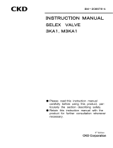
2)
Internal structure and parts list
No. Parts name Material
① Knob Aluminum alloy
② Lock nut Aluminum alloy
③ Needle Stainless steel
④ Needle guide Aluminum alloy
⑤ Check bracket Aluminum alloy
[Stainless steel]
⑥ O ring Nitrile rubber
⑦ Packing seal Hydrogen nitrile rubber
⑧ Body Aluminum alloy
⑨ Bolt Copper alloy
⑩ O ring Nitrile rubber
⑪ Steel ball Stainless steel
⑫ Gasket Steel, Nitrile rubber
Value in [ ] is for fine speed type
3) JIS symbol
SC-M※-S SC-M※-L
SC-M※-F SC-M※-A
PRODUCT
1

[SM-195407-A]
―7―
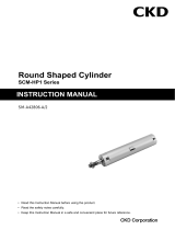
1.4 Fundamental circuit diagram
The fundamental circuit diagram or speed control valve is as per shown below.
1)
Meter-out connection
2)
Meter-in connection
Compressed air
Filter
Speed control valve
Solenoid
valve
Pressure gage
Silencer
Regulator
Double acting
cylinder
Filter
Compressed air
Speed control valve
Solenoid
valve
Pressure gage
Silencer
Regulator
Double acting
cylinder

[SM-195407-A]
-8-
2. OPERATION
Setting the cylinder speed
Turning the knob ① clockwise
reduces the speed of cylinder,
finally closing the control valve,
while turning it counterclockwise
increases the speed of cylinder. To
build a meter out circuit, close the
control valve first by turning its
knob ① clockwise, then connect it
to the piping so that the casted JIS
symbol on the body ③ matches
with the direction of flow as per
designed schematic.
While giving pressure to the circuit, turn the knob ① of control valve
counterclockwise until the required speed of the cylinder is set. Once the
position of the knob ① is set, make sure to tighten up the lock nut ②.
(
Meter-out connection
)
OPERATION
2
Compressed air
F
ilter
Speed control valve
Solenoid
valve
Pressure gage
Silencer
Regulator
Double acting
cylinder

[SM-195407-A]
―9―
3. SAFETY PRECAUTIONS
1) Always use this product within its specifications.
2) The product is designed only for compressed air. Do not
flow other media into this product.
3) Before starting the maintenance work, stop the air flow
completely and make sure that no residual pressure
remains inside the product.
4) When installing this product, always observe the flow
direction. If the product is installed in the incorrect
orientation, the speed cannot be controlled, causing the
actuator to be projected.
1)Confirm that the product will withstand the working environment.
This product cannot be used in environments where functional obstacles could occuer.
Such environments include high temperatures, a chemical atmosphere, or where
chemicals, vibration, moisture, water drip, or gas are present, or where ozone is
generated.
2) This valve can not be used as a stop valve that has no leakage. Slight leakage is allowed in
product specifications.
3) Check that lock nuts are not loose.
4) Fully close the needle, and open to adjust speed.
If the needle is opened, the actuator could pop out suddenly and pose a hazard.
5) When knob is fully closed, the contact portion of the needle air leakage. Take care to
tighten the knob lightly.
6) The needle valve has dislocation prevention that could break if the needle is turned too far.
Check the number of turns for the product used.
CAUTION
2
!
WARNING
:

[SM-195407-A]
-10-
4. INSTALLATION
4.1 Fluid
1) Use the compressed air, filtrated and
dehumidified. Carefully select a filter
of an adequate filtration rate (5µm or
lower preferred), flow rate and its
mounting location (asclosest to
directional control valve as possible)
2) Be sure to drain out the accumulation
in filter periodically.
3) Note that the intrusion of carbide of
compressor oil (such as carbon or tarry
substance) into the circuit causes
malfunction of solenoid valve and
cylinder. Be sure to carry out thorough
inspection and maintenance of
compressor.
4.2 Piping
1) For piping beyond the filter, use pipes
that hardly get corroded such as
galvanized pipes, nylon tubes, rubber
tubes,etc. (Refer to Selection Guide Table
for Related Equipment.)
2) See to it that the pipe connecting cylinder
and solenoid valve has effective sectional
area needed for the cylinder to drive at
specified speed.
(Refer to Selection Guide Table for
Related Equipment.)
3) Install filter preferably adjacent upper-stream to solenoid valve for eliminating rust,foreign
substance and drain in the pipe.
4) Flush air into the pipe to blow out foreign substances and chips before piping.
5) Pipe so that piping connections do not become dislocated due to device movement, vibration, etc.
6) After completing the piping, do not apply a high pneumatic pressure suddenly but gradually
increase the pressure of compressed air.
7) After completing the piping, check each speed controller in the piping system for air leakage
before supplying compressed air.
8)
Tighten to the correct torque when connecting pipes.
Connected
screw
Tightening
torque
(N・m)
M3 0.3~0.6
M5 1.0~1.5
INSTALLATION
4
Compressed air Filtrated air
Drain
Upper limit
of drain

[SM-195407-A]
―11
―
5.MAINTENANCE
5.1 Trouble shooting
Malfunction
Cause
Remedies
1.
Pipes are connected
in the incorrect
direction.
Check the marks showing the
compressed air flow direction.
Cylinder speed cannot
be changed even though
the knob is adjusted.
2.
Dust is caught in the
speed controller.
Flush the air from both ports
alternately to blow out the dust.
6. HOW TO ORDER
Port size Shape Control method Flow characteristics
M3
M3×0.5
S
Straight Blank
Meter-out type
Blank
Standard type
M5
M5×0.8
L
Elbow I Meter-in type O Low speed type(only M5)
F
Flat
F Fine speed type(only M5)
A
Adjustable
Model no. of SC-*-S-I can not be selected . Install SC-*-S with reversing IN and OUT side.
MAINTENANCE
5
HOW TO ORDER
6
SC M5
A
I
O
1
2
3
4
1
2
3
4
-
 1
1
-
 2
2
-
 3
3
-
 4
4
-
 5
5
-
 6
6
-
 7
7
-
 8
8
-
 9
9
-
 10
10
-
 11
11
-
 12
12


Ask a question and I''ll find the answer in the document
Finding information in a document is now easier with AI
Related papers
-
 CKD CHB・CHBF・CHG Series User manual
-
 CKD SLW-H Series User manual
-
 CKD MNRJB500 Series User manual
-
 CKD APS Series User manual
-
 CKD 3QE1・M3QE1・M3QZ1 Series User manual
-
 CKD SC1-※-W Series User manual
-
 CKD SKH-4 Series User manual
-
 CKD 3KA1_M3KA1 Series User manual
-
 CKD 4KA1_4KB1_M4KA1_M4KB1 User manual
-
 CKD SCM-HP1 Series User manual


