Page is loading ...

SM-P00124-A
INSTRUCTION MANUAL
3QE1
M3QE1, M3QZ1
●
Please read this instruction manual care-
fully before using this product, particularly
the section describing safety.
●
Retain this instruction manual with the
product for further consultation whenever
necessary.

[SM-P00124-A]
―
1
―
Safety precautions
When designing and manufacturing a device using CKD products, the manufacturer is obligated to manufacture a safe product by confirming
safety of the system comprising the following items:
Device mechanism
Pneumatic or water control circuit
Electric control that controls the above
It is important to select, use, handle, and maintain the product appropriately to ensure that the CKD product is used safely.
Observe warnings and precautions to ensure device safety.
Check that device safety is ensured and manufacture a safe device.
1.
This product is designed and manufactured as a general industrial machine part. It must be
handled by someone having sufficient knowledge and experience.
2.
Use this product within its specifications.
This product cannot be used beyond its specifications. Additionally, the product must not be modified or machined.
This product is intended for use in general industrial devices and parts. Use beyond such conditions is not considered. Consult with
CKD for details when using the product beyond the unique specification range, outdoors, or in the following conditions or environments.
In any case, measures for safety shall be provided when the vavle malfunctions.
①
Use for special applications requiring safety including nuclear energy, railroad, aviation, ship, vehicle, medical equipment, equipment
or applications coming into contact with beverage or food, amusement equipment, emergency shutoff circuits, press machine, brake
circuits, or for safeguard.
②
Use for applications where life or assets could be adversely affected, and special safety measures are required.
3.
Observe corporate standards and regulations, etc., related to the safety of device design
and control, etc.
ISO4414, JIS B 8370 (pneumatic system rules)
JFPS2008 (principles for pneumatic cylinder selection and use)
Including High Pressure Gas Maintenance Law, Occupational Safety and Sanitation Laws, other safety rules, standards and regulations, etc
4.
Do not handle, pipe, or remove devices before confirming safety.
①
Inspect and service the machine and devices after confirming safety of the entire system related to this product.
②
Note that there may be hot or charged sections even after operation is stopped.
③
When inspecting or servicing the device, turn off the energy source (air supply or water supply), and turn off power to the facility.
Release any compressed air from the system, and pay enough attention to possible water leakage and leakage of electricity.
④
When starting or restarting a machine or device that incorporates pneumatic components, make sure that system safety, such as
pop-out prevention measures, is secured.
WARNING

[SM-P00124-A]
-
2
-
5.
Observe warnings and cautions on the pages below to prevent accidents.
The safety cautions are ranked as "DANGER", "WARNING" and "CAUTION" in this
section.
:
When a dangerous situation may occur if handling is mistaken leading
to fatal or serious injuries, or when there is a high degree of emer-
gency to a warning.
:
When a dangerous situation may occur if handling is mistaken leading
to fatal or serious injuries.
:
When a dangerous situation may occur if handling is mistaken leading
to minor injuries or physical damage.
Note that some items described as "CAUTION" may lead to serious results depending on the
situation. In any case, important information that must be observed is explained.
Precautions with regard to guarantee
Guarantee period
The guarantee period of our product shall be one (1) year after it is delivered to the place specified by the customer.
Guarantee coverage
If any failure for which CKD CORPORATION is recognized to be responsible occurs within the above warranty period, a substitute or
necessary replacement parts shall be provided free of charge, or the product shall be repaired free of charge at the plant of CKD COR-
PORATION.
However, the guarantee excludes following cases:
①
Defects resulting from operation under conditions beyond those stated in the catalogue or specifications.
②
Failure resulting from malfunction of the equipment and/or machine manufactured by other companies.
③
Failure resulting from wrong use of the product.
④
Failure resulting from modification or repairing that CKD CORPORATION is not involved in.
⑤
Failure resulting from causes that could not be foreseen by the technology available at the time of delivery.
⑥
Failure resulting from disaster that CKD is not responsible of.
Guarantee stated here covers only the delivered products. Any other damage resulting from failure of the delivered products is not covered
by this guarantee.
Confirmation of product compatibility
Our customer shall be responsible of confirming compatibility of our product used in our customer
’
s system, machinery or device
DANGER
WARNING
CAUTION

[SM-P00124-A]
―
3
―
UNPACKING (Section 3)
Bags containing solenoid valves should be opened only
when you are ready to connect the valves to the pipes im-
mediately afterward.
・ If bags are opened before the valves are ready to be
connected to the pipes, the entry of foreign matter from
the piping ports could cause the solenoid valves to fail or
malfunction.
INSTALLATION (Section 4)
If you have to use the product under conditions that are
different from the specified conditions or if you intend to
use the product for a special application, be sure to consult
us about the product specifications before using the prod-
uct.
ENVIRONMENT (Section 4.1)
CAUTION:
a) In a dusty environment, foreign matter may enter even
through the exhaust port.
・ The movement of the exhaust valve causes a respire
tory action at the exhaust valve, which may cause inha-
lation of foreign matter near the exhaust port. This po-
tential situation would be worse if the exhaust port is
facing upward. Attach a silencer to the exhaust port or
have the exhaust port face downward.
b) Keep the solenoid valve system dry. Take care to avoid
direct contact with dripping water or splashes of cutting
oil.
・ If the solenoid valve system is wet by a direct contact
with water or cutting oil, an electrical leak or burnt so-
lenoid coils may result. Protect the solenoid valve sys-
tem by using a cover or by installing it inside a paneled
casing. If the cylinder rod is splashed with cutting oil,
the oil may penetrate through the cylinder into the sec-
ondary side piping of the solenoid valve. This must be
prevented to avoid malfunctions. Consult us for preven-
tive measures.
c) The coils will produce heat.
・ Particularly if the solenoid valve system is installed in a
control board or if the solenoid coils need to be ener-
gized for a long time, consider providing sufficient venti-
lation to release the heat. The coils can get very hot.
d) Do not use the solenoid valve system in an atmos-
phere that includes a corrosive gas or solvent vapors.
・ Do not use the solenoid valve system in an atmosphere
that includes a corrosive gas such as the sulfur dioxide
gas or in an atmosphere that includes solvent vapors.
e) Vibrations and shocks
・ Do not subject the solenoid valve system to vibrations
50m/s
2
or stronger or shocks 300m/s
2
or stronger.
f) Avoid using the solenoid valve system in a humid en-
vironment because the humidity is likely to cause
condensation with a change in the temperature.
!
CAUTION :
!
CAUTION :
!

[SM-P00124-A]
-
4
-
g) Do not use the normal type solenoid valves for an ap-
plication that requires conformity with explosion-proof
specifications. Choose explosion-proof solenoid valve.
The packing and gaskets may deteriorate sooner
h) Than usual if used in an atmosphere with a higher than
normal density of ozone (for example, the atmosphere
near a beach or in an area with frequent thunder-
storms
・ Consult us for the packing and gaskets to be used in an
atmosphere with a higher ozone density.
i) There is no resistance to surges caused by overvolt-
age from switching and lightning transients(CE Mark-
ing :IEC61000-4-5). Please take measures against
surges on the equipment side.
INSTALLATION (Section 4.2)
a) When installing a solenoid valve unit, never attempt to
hold it in position by means of the pipes connected to it.
・ Mount the solenoid valve by applying the mounting
screws and/or mounting plate to the solenoid valve.
b) Tighten the screws with proper torque. If the assembly
or tightening is not conducted properly, it may cause
some air leakage, falling-off of products, or screw
damaging.
PIPING (Section 4.3)
a) Observe the recommended tightening torque when
connecting pipes.
・ Observing the recommended tightening torque
prevents air leakage and damage to the screw threads.
To prevent damage to the screw threads, first use your
hand to lightly tighten the screw and then use a tool to
tighten the screw to the recommended torque.
b) Make sure that the pipes will not be disconnected at
the joints by mechanical movements, vibrations or ten-
sion.
・ If the exhaust piping of the pneumatic circuit is
disconnected, the actuator speed control is disabled.
・ If the above happens to a chuck holding mechanism,
the chuck will open. The inadvertent opening of the
chuck may cause a serious accident.
c) When supplying the compressed air for the first time
after completing the piping, be sure to check every
joint in the piping for air leakage.
d) When supplying the compressed air for the first time
after completing the piping, increase the air pressure
gradually but never introduce a highly-pressurized air
suddenly.
・ A sudden introduction of a highly-pressurized air may
disconnect pipes at joints and/or cause the tubes to
jump around, any of which may cause an injury.
!
WARNING :
!
CAUTION :

[SM-P00124-A]
―
5
―
e) Do not decrease the inside diameter of the piping from
any of the solenoid valve exhaust ports to a diameter
less than the exhaust pipe connecting port size.
・ Normal operation of the actuator depends on the
smoothness of the exhaust flow. With a manifold sys-
tem, a restriction to the exhaust flow may prevent
normal operation of other solenoid valves.
f) Removal of foreign matter
・ The 1(P) port includes a mesh filter as standard to
prevent suction of foreign matter into the valve, but
the filter is not capable of removing fine dust.
g) Do not use the product as emergency cutout solenoid
valve.
・ Starting response time can be late, when leaving un-
der elevated pressure for a long time.
WIRING (Section 4.4)
Turn off the power before wiring. Do not touch or put wet
hands close to any terminal while power is on. Doing so
may cause electric shock. Before wiring, read the instruc-
tion manual carefully and understand the instructions.
・ A person who wires needs to have knowledge for safely
performing such operation based on the understanding about
the mechanisms and operating principles of solenoid valves.
a) Before supplying the power, check the power supply
voltage and the current type (AC or DC).
b) Do not apply stress to the lead wires.
・ Undue stress may cause such problems as a break in the
wire or disconnection of the contact terminal.
c) The voltage drop may be caused with the simultane-
ous energization and/or cable length. Confirm the
voltage drop on the solenoid valve is within 10% of its
rated voltage.
d) Connect this product with the output unit. In case the
product is connected with the input unit, it may result in
serious trouble(s), not only on these apparatuses but al-
so on the peripheral equipment.
MANUAL OVERRIDE (Section 5.2)
a) Do not operate the manual override with excessive
force. Doing so may damage it.
・ Non-locking manual override:15~25N
・ Locking manual override:Turn with a light force with a
tool. (0.1N・m or less)
b) When using the locking manual override, be sure to
release the lock before normal operation. Failure to do
so may cause malfunction or failure.
c) Before using the manual override, make sure that nobody
is present near the cylinder to be activated.
!
WARNING
:
!
WARNING :
!
CAUTION :

[SM-P00124-A]
-
6
-
AIR QUALITY (Section 5.3)
a) Do not supply anything other than compressed air or low
vacuum.
b) Supply clean compressed air without any mixture of
corrosive gas.
a)
Compressed air usually contains a large amount of
drain, oxidized oil, tar, foreign matter, and rust from
the piping. Filter out those elements in the supplied air
because they may cause a malfunction and decrease
service life. In addition, clean the exhaust before it is
released to the air to minimize pollution.
b) Basically, the product is designed as oil less specifica-
tions, however if you prefer to supply oil, use the class 1
turbine oil (additive-free) ISO VG32.
・ Once you have lubricated a pre-lubricated valve, the
valve is no longer capable of running without being lubri-
cated from the outside. Do not leave the valve without
lubrication. Keep it lubricated.
c) Do not use spindle oil or machine oil. They induce
expansion of the rubber parts, which will cause mal-
function.
d) You can't use under negative pressure。In case of
used in mixed conditions of negative and positive
pressure, like a vacuum break circuit, it malfunctions.
ELECTRIC CIRCUITS (Section 5.4)
a) Check for the presence of any current leak from the
external control device because it may cause an er-
roneous valve operation.
・
When a programmable controller or a similar control de-
vice is used, a current leak may prevent the normal re-
turning of the valve when the solenoid is de-energized.
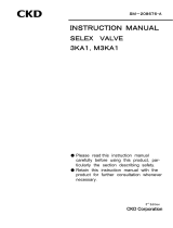
b) Restriction on current leak
・
When controlling solenoid valves using a programmable
controller or a similar control device, make sure that the
current leak in the programmable controller output is
equal to or less than the level shown in the table below.
A current leak larger than the allowable level may cause
an erroneous valve operation.2
!
WARNING :
!
CAUTION :
!
CAUTION :
Leakage
current
C
R
Programmable
controller
AC100V 1.0 mA or lower
DC3V 8.0 mA or lower
DC5V 4.8 mA or lower
DC12V 1.6 mA or lower
DC24V 1.0 mA or lower
CR Circuit
Contact
Solenoid valve

[SM-P00124-A]
―
7
―
a) The surge suppressor limits the surge voltage gener-
ating from the solenoid valve, which reaches several
hundred volts, to a low voltage level bearable for
output contacts. This function may be insufficient for
some output circuits and the voltage may cause
breakage or malfunction. Check the surge voltage
limitation level of the solenoid valve in your circuit,
the dielectric voltage and circuit configuration of the
output devices and the delay for recovery to check
for serviceability. If necessary, install another meas-
ure against surges. The 4GR Series solenoid valves
equipped with a surge suppressor suppress the ter-
minal-to-terminal reverse voltage surge generating
upon shutoff, to the level shown in the table below
.
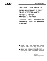
b) When the output unit is an NPN type, a surge voltage
of “voltage stated in above table” + “power voltage”
may be applied to the output transistor. To avoid this
trouble, it may be required to separately install a
contact protection circuit or to choose option "s".
.
In case of 3V DC About 6.2V
In case of 5V DC About 13V
In case of 12V DC About 27V
In case of 24V DC About 47V
In case of option "S ", "E "
About 1V
!
CAUTION:
< Example 1
Separate installation of
output transistor protection circuit >
Programmable
controller side
Solenoid
valve side
< Example 2 Separate installation of output transistor protection circuit >
Solenoid
valve side
Programmable
controller side

[SM-P00124-A]
-
8
-
c)If another devices or solenoid valves are connected to
the solenoid valve in parallel, the reverse surge voltage
occurred while the power of the solenoid valve is OFF is
applied to those devices. When the solenoid valve with
the surge killer for DC24V is used, the surge voltage
reaches minus several tens V due to the type, and an-
other device connected in parallel may be broken or be
malfunctioned by this voltage of reverse polarity. Do not
connect in parallel the solenoid valve and another device,
which are weak of the voltage of reverse polarity (for
example LED lamp).
When a few solenoid valves are functioned in parallel,
the surge of another solenoid valve is flowed to surge kill-
er of one solenoid valve with it, and therefore it may make
burning breakage the surge killer due to current value.
When a few solenoid valves with the surge killer are
functioned in parallel, the surge current converges on the
surge killer of the lowest limiting voltage, and it may make
burning breakage similarly. If the solenoid valves are same
model number, the surge killer may make burning breakage
at worst because their limiting voltages vary widely. Do
not function in parallel a few solenoid valves
d)
When the surge killer installed in the solenoid valve is
broken by the over voltage or the over current from be-
sides the solenoid valve, it short-circuits in many cases.
Therefore, after broken it, a large current is flowed while
the output is ON, and the output circuit or the solenoid
valve may be broken or get a fire at worst. Do not keep a
continuous energizing while the solenoid valve is broken.
In addition, install the protection circuit of the over cur-
rent at the power source or the functioning circuit, or
use the power source with the protection of over current
not to continue flowing a large current.

[SM-P00124-A]
―
9
―
■
About AC models
(1) The AC voltage models have a built-in full-wave rectifi-
er circuit. If an SSR is used to turn on and off the so-
lenoid valve, the solenoid valve may cause recovery
failure depending on the type of the SSR. Carefully se-
lect the SSR. (We recommend that you consult with the
relay or PLC manufacturer.)
(2) When the solenoid valve is used in the continuously en-
ergized state, the coil’s outer surface will become hot.
Do not touch the coil while the power is on. Doing so
may cause burn injury.
PERIODIC INSPECTION (Section 6.1)
Before providing a maintenance service, cut the power and
the supply of compressed air and confirm the absence of
residual pressure.
・
The above is required to ensure safety.
Regularly perform the daily and periodic inspections to
correctly maintain product performance.
・If the product is not correctly maintained, product perfor-
mance may deteriorate dramatically, resulting in a shorter
service life, fractures of components, and malfunctions.
REPLACING OF THE SOLENOID VALVE (Section 6.2)
Before replacing solenoid valves, read the instruction man-
ual carefully and understand the instructions.
・ A person who replaces a solenoid valve system needs to
have knowledge for safely performing such operation
based on the understanding about the mechanisms and
operating principles of solenoid valves.
・ Pneumatic technician certification test class 2 or higher.
!
WARNING:
!
CAUTION :
!
WARNING :
!
CAUTION :

Created 2022.05.17
-
10
-
INDEX
3QE1,
M3QE1, M3QZ1
Manual No.
SM-P00124-A
1.
PART NAME AND DESCRIPTION
······································· 11
2.
INTERNATIONAL SYSTEM OF UNITS (SI)
AND PORT INDICATION
········ 12
3.
UNPACKING
······································································ 13
4.
INSTALLATION
································································· 14
4.1
Environment
································································ 14
4.2
Installation
··································································· 16
4.3
Piping
·········································································· 17
4.4
Wiring
·········································································· 20
5.
OPERATING RECOMMENDATION
5.1
Operation Explanation
·················································· 23
5.2
Manual Override
·························································· 24
5.3
Air Quality
··································································· 25
5.4
Electric Circuits
··························································· 26
6.
MAINTENANCE
6.1
Periodic Inspection
······················································ 32
6.2
Replacing of The Solenoid Valve
··································· 30
6.3
Internal Structure and Parts List
··································· 33
7.
TROUBLE SHOOTING
······················································· 34
8.
PRODUCT SPECIFICATIONS AND HOW TO ORDER
8.1
Product Specifications
················································· 36
8.2
How to Order
······························································ 38

[SM-P00124-A]
―
11
―
PRODUCT
1
1.
PART NAME AND DESCRIPTION
3
QE
1
(
Without manual override
)
3
QE
1
(
Non-locking manual override
)
3
QE
1
(
Locking manual override
)
M
3
QE/Z
No. Part Name
Explanation
① Wire connection Its connections to the electric circuit
② Valve unit This is sub plate piping.
③ Mounting screw Two screws are provided for each individual valve so as to fix the valve unit to various
bases.
④ Sub plate
This sub plate is assembled to use it in the sub plate piping specifications.
⑤ Mounting hole
The sub plate and manifold base can be secured with screws M2.5 and M3, respectively.
⑥ Manual override
(1→2port) It is used for manual operation. The non-locking and locking types are available.
⑦ Masking plate
It masks the clear space of valve unit in the manifold.
⑧ Manifold base
It uses in case of performing common supply or common exhaust to several valve units.
⑨ Piping port
“1(P)”, “3(R2)/5(R1)”, and “2(B)/4(A)” show the supply, exhaust, and output ports, respectively.
⑩ Masking plate mounting screw
Each masking plate has two screws. They are used to secure the masking plate on the
manifold base.

[SM-P00124-A]
-
12
-
SI UNIT
2
2.INTERNATIONAL SYSTEM OF UNITS (SI) AND PORT INDICATION
Conversion between International System of Units (SI) and Conventional Units
In this manual, values are expressed using the International System of Units (SI).
Use the table below to convert them into values expressed in conventional units.
Table of conversion between SI units and conventional units
(The values printed in Bolds fonts are values given in the International System of Units (SI)):
Force
N dyn kgf
1 1×10
5
1.01972×10
-1
1×10
-5
1 1.01972×10
-6
9.80665 9.80665×10
5
1
Stress
Pa or N/m
2
MPa or N/mm
2
kgf/mm
2
kgf/cm
2
1 1×10
-6
1.01972×10
-7
1.01972×10
-5
1×10
6
1 1.01972×10
-1
1.01972×10
9.80665×10
6
9.80665 1 1×10
2
9.80665×10
4
9.80665×10
-2
1×10
-2
1
Note:1Pa=1N/m
2
, 1MPa=1N/mm
2
Pressure
Pa kPa MPa bar kgf/cm
2
atm mmH2O MmHg or Torr
1 1×10
-3
1×10
-6
1×10
-5
1.01972×10
-5
9.86923×10
-6
1.01972×10
-1
7.50062×10
-3
1×10
3
1 1×10
-3
1×10
-2
1.01972×10
-2
9.86923×10
-3
1.01972×10
2
7.50062
1×10
6
1×10
3
1 1×10 1.01972×10 9.86923 1.01972×10
5
7.50062×10
3
1×10
5
1×10
2
1×10
-1
1 1.01972 9.86923×10
-1
1.01972×10
4
7.50062×10
2
9.80665×10
4
9.80665×10 9.80665×10
-2
9.80665×10
-1
1 9.67841×10
-1
1×10
4
7.35559×10
2
1.01325×10
5
1.01325×10
2
1.01325×10
-1
1.01325 1.01323 1 1.03323×10
4
7.60000×10
2
9.80665 9.80665×10
-3
9.80665×10
-6
9.80665×10
-5
1×10
-4
9.67841×10
-5
1 7.35559×10
-2
1.33322×10
2
1.33322×10
-1
1.33322×10
-4
1.33322×10
-3
1.35951×10
-3
1.31579×10
-3
1.35951×10 1
Note:1Pa=1N/m
2
Example (converting a pressure value):
1kgf/cm
2
→
0.0980665Mpa 1MPa
→ 1.01972×10kgf/cm
2

[SM-P00124-A]
―
13
―
UNPACKING
3
3. UNPACKING
Bags containing solenoid valves should be opened only
when you are ready to connect the valves to the pipes
immediately afterward.
・ If bags are opened before the valves are ready to be
connected to the pipes, the entry of foreign matter
from the piping ports could cause the solenoid valves to
fail or malfunction.
1) Check the model number imprinted on the product to make sure that the product
you received is exactly the product you ordered.
2) Check the exterior of the product for any damage.
3) Before using the product, read the supplied documentation.
!
CAUTION :

[SM-P00124-A]
-
14
-
INSTALLATION
4
4. INSTALLATION
If you have to use the product under conditions that are
different from the specified conditions or if you intend to
use the product for a special application, be sure to consult
us about the product specifications before using the prod-
uct.
4.1
Environment
a) In a dusty environment, foreign matter may enter even
through the exhaust port.
・ The movement of the exhaust valve causes a res-
piratory action at the exhaust valve, which may cause
inhalation of foreign matter near the exhaust port. This
potential situation would be worse if the exhaust port is
facing upward. Attach a silencer to the exhaust port or
have the exhaust port face downward.
b) Keep the solenoid valve system dry. Take care to avoid
direct contact with dripping water or splashes of cutting
oil.
・ If the solenoid valve system is wet by a direct con-
tact with water or cutting oil, an electrical leak or burnt
solenoid coils may result. Protect the solenoid valve
system by using a cover or by installing it inside a pan-
eled casing. If the cylinder rod is splashed with cutting
oil, the oil may penetrate through the cylinder into the
secondary side piping of the solenoid valve. This must
be prevented to avoid malfunctions. Consult us for
preventive measures.
c) The coils will produce heat.
・ Particularly if the solenoid valve system is installed in a
control board or if the solenoid coils need to be ener-
gized for a long time, consider providing sufficient ven-
tilation to release the heat. The coils can get very hot.
d) Do not use the solenoid valve system in an atmosphere
that includes a corrosive gas or solvent vapors.
・ Do not use the solenoid valve system in an at-
mosphere that includes a corrosive gas such as the
sulfur dioxide gas or in an atmosphere that includes
solvent vapors.
e) Vibrations and shocks.
・ Do not subject the solenoid valve system to
vibrations 50m/s
2
or stronger or shocks 300m/s
2
or
stronger.
f)
Avoid using the solenoid valve system in a humid envi-
ronment because the humidity is likely to cause con-
densation with a change in the temperature.
!
CAUTION :
!
CAUTION :

[SM-P00124-A]
―
15
―
INSTALLATION
4
g)
Do not use the normal type solenoid valves for an ap-
plication that requires conformity with explosion-proof
specifications. Choose explosion-proof solenoid valves
instead.
h) The packing and gaskets may deteriorate sooner than
usual if used in an atmosphere with a higher than normal
density of ozone (for example, the atmosphere near a
beach or in an area with frequent thunderstorms).
・ Consult us for the packing and gaskets to be used in an
atmosphere with a higher ozone density
i)
There is no resistance to surges caused by over-
voltage from switching and lightning transients(CE
Marking :IEC61000-4-5). Please take measures
against surges on the equipment side.

[SM-P00124-A]
-
16
-
INSTALLATION
4
4.2 Installation
Then installing a solenoid valve unit, never attempt to hold
it in position by means of the pipes connected to it.
・ Mount the solenoid valve by applying the mounting
screws and/or mounting plate to the solenoid valve.
4.2.1 A work space for installation, removal, wiring, and piping operations
should be provided around the installed solenoid valve system.
4.2.2 Direct mounting
1) Unit Sub plate Type
Use two mounting holes
2) Manifold Type
Use two mounting holes
!
WARNING :
2-
φ
2.7
(Mounting hole)
2-
φ
3.5
(Mou
n
ting hole)

[SM-P00124-A]
―
17
―
INSTALLATION
4
4.3 Piping
a) Observe the recommended tightening torque when
connecting pipes.
・
Observing the recommended tightening torque
prevents air leakage and damage to the screw threads.
To prevent damage to the screw threads, first use
your hand to lightly tighten the screw and then use a
tool to tighten the screw to the recommended torque.
b) Make sure that the pipes will not be disconnected at
the joints by mechanical movements, vibrations or
tension.
・
If the exhaust piping of the pneumatic circuit is
disconnected, the actuator speed control is disabled.
・
If the above happens to a chuck holding mechanism,
the chuck will open. The inadvertent opening of the
chuck may cause a serious accident.
c) When supplying the compressed air for the first time
after completing the piping, be sure to check every
joint in the piping for air leakage.
d) When supplying the compressed air for the first time
after completing the piping, increase the air pressure
gradually but never introduce a highly-pressurized air
suddenly.
・
A sudden introduction of a highly-pressurized air may
disconnect pipes at joints and/or cause the tubes to
jump around, any of which may cause an injury.
e) Do not decrease the inside diameter of the piping
from any of the solenoid valve exhaust ports to a
diameter less than the exhaust pipe connecting port
size.
・
Normal operation of the actuator depends on the
smoothness of the exhaust flow. With a manifold sys-
tem, a restriction to the exhaust flow may prevent
normal operation of other solenoid valves.
f)
Removal of foreign matter
・
The 1(P) port includes a mesh filter as standard to
prevent suction of foreign matter into the valve, but
the filter is not capable of removing fine dust.
g)
Do not use the product as emergency cutout sole-
noid valve.
・
Starting response time can be late, when leaving under
elevated pressure for a long time.
A
ppropriate tightening torque
Connecting
screw Tightening torque N・m
M5 1.0~1.5
Rc1/8 3~5
!
CAUTION :

[SM-P00124-A]
-
18
-
INSTALLATION
4
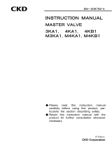
4.3.1 Seal material
When using seal material, take care to avoid getting it in the pipes or overflowing on the exterior sur-
face of the pipes.
When applying fluororesin sealing tape to the screw threads, wind the tape two or three times around
the threads but leave the one or two threads at the pipe end uncovered. Firmly press the tape
against the threads using the tip of your fingernail. When applying liquid type seal material, apply the
material to all the threads except one or two threads at the pipe end and take care not to apply too
much of it.
Never apply the seal material to the female threads in the device side piping port.
4.3.2 Flushing
Before connecting pipes, flush the interiors of the tubes, solenoid valves, and connected
devices to remove foreign matter.
4.3.3 About M5 joint
M5 seal it with gasket (model : FGS). Don’t tight while increasing Pressure. Consider a
trouble of emergency, Design and enforce to be possible to remove and mount of a
valve.
4.3.4 Exhaust port
Minimize the restriction to the flow of the exhaust air because such restriction may
cause a delay in the cylinder response. If such a delay happens, the speed needs to be
adjusted between the cylinder and solenoid valve.
●
Seal Tape
●
Seal Material(Paste or liquid)
(
Correct
)
(
Correct
)
(Inc
orrect
)
(Inc
orrect
)

[SM-P00124-A]
―
19
―
INSTALLATION
4
4.3.5 Pipe connections
(1) Tubes to be used
For use with solenoid valves with one-touch joints, select tubes of the type specified
by us.
Soft nylon tubes (F-1500 Series)
Urethane tubes (U-9500 Series)
*
For the φ 1.8 push-in joint (C18), use UP-9402 (urethane).
(2) For installation at a site that has spatters in the air, select incombustible tubes or
metal pipes.
(3)
When selecting from tubes commercially available, carefully study the accuracy of the
outside diameter as well as the wall thickness and the hardness. The hardness of an
urethane tube should be 93°C or more (as measured by a rubber hardness meter).
With a tube that does not have a sufficient accuracy of the outside diameter or the
specified hardness, a decrease in the chucking force may cause disconnection or dif-
ficulty in inserting.
Tube dimensions
Outside diameter
mm
Inside diameter mm
Nylon Urethane
φ1.8 - φ1.2
φ3 - φ2
φ4 φ2.5 φ2
φ6 φ4 φ4
(4) Minimum bending radius of tubes
Observe the minimum bending radius of tubes. Neglecting the minimum bending radius
may cause disconnection or leaks.
Tube bore
Minimum bending radius
mm
Nylon
Urethane
φ
1.8
-
4
φ
3
-
8
φ
4 10 10
φ
6 20 20
(5) Cutting a tube
To cut a tube, use a tube cutter to cut the tube perpendicularly to the length of the
tube. Inserting an obliquely cut end of a tube may cause air leakage.
(6) Tube connections
Do not bend a tube immediately at where it is connected to the joint but lead it out
straight from the end of the joint for a length equal to or greater than the outside
diameter of the tube. The tension applied sideways through the tube should not ex-
ceed 40N.
(About 5N for C18)
Outside diameter allowance
Soft or hard nylon ±0.1mm
Urethane φ1.8,φ3 ±0.1mm
Urethane φ4,φ6 +0.1mm
-0.15mm
/