Page is loading ...

SAFETY WARNING
Only qualified personnel should install and service the equipment. The installation, starting up, and
servicing of heating, ventilating, and air-conditioning equipment can be hazardous and requires specific
knowledge and training. Improperly installed, adjusted or altered equipment by an unqualified person could
result in death or serious injury. When working on the equipment, observe all precautions in the literature
and on the tags, stickers, and labels that are attached to the equipment.
February 2013 VRF-SVX31A-EN
Installation, Operation,
and Maintenance
Variable Refrigerant Flow System
Big Duct Indoor Unit Series
Models: 4TVA0096B100NB, 4TVA0076B100NB

© 2013 Trane All rights reserved VRF-SVX31A-EN
Introduction
Read this manual thoroughly before operating or servicing
this unit.
Warnings, Cautions, and Notices
Safety advisories appear throughout this manual as
required. Your personal safety and the proper operation of
this machine depend upon the strict observance of these
precautions.
Important Environmental Concerns
Scientific research has shown that certain man-made
chemicals can affect the earth’s naturally occurring
stratospheric ozone layer when released to the
atmosphere. In particular, several of the identified
chemicals that may affect the ozone layer are refrigerants
that contain Chlorine, Fluorine and Carbon (CFCs) and
those containing Hydrogen, Chlorine, Fluorine and Carbon
(HCFCs). Not all refrigerants containing these compounds
have the same potential impact to the environment. Trane
advocates the responsible handling of all refrigerants-
including industry replacements for CFCs such as HCFCs
and HFCs.
Important Responsible Refrigerant
Practices
Trane believes that responsible refrigerant practices are
important to the environment, our customers, and the air
conditioning industry. All technicians who handle
refrigerants must be certified. The Federal Clean Air Act
(Section 608) sets forth the requirements for handling,
reclaiming, recovering and recycling of certain refrigerants
and the equipment that is used in these service procedures.
In addition, some states or municipalities may have
additional requirements that must also be adhered to for
responsible management of refrigerants. Know the
applicable laws and follow them.
Copyright
This document and the information in it are the property of
Trane and may not be used or reproduced in whole or in
part, without the written permission of Trane. Trane
reserves the right to revise this publication at any time and
to make changes to its content without obligation to notify
any person of such revision or change.
Trademarks
All trademarks referenced in this document are the
trademarks of their respective owners.
The three types of advisories are defined as follows:
WARNING
Indicates a potentially hazardous
situation which, if not avoided, could
result in death or serious injury.
CAUTIONs
Indicates a potentially hazardous
situation which, if not avoided, could
result in minor or moderate injury. It
could also be used to alert against
unsafe practices.
NOTICE
Indicates a situation that could result in
equipment or property-damage only.
WARNING
Proper Field Wiring and Grounding
Required!
Failure to follow code could result in death or serious
injury. All field wiring MUST be performed by qualified
personnel. Improperly installed and grounded field
wiring poses FIRE and ELECTROCUTION hazards. To
avoid these hazards, you MUST follow requirements for
field wiring installation and grounding as described in
NEC and your local/state electrical codes.
WARNING
Personal Protective Equipment (PPE)
Required!
Failure to wear proper PPE for the job being undertaken
could result in death or serious injury. Technicians, in
order to protect themselves from potential electrical,
mechanical, and chemical hazards, MUST follow
precautions in this manual and on the tags, stickers,
and labels, as well as the instructions below:
• Before installing/servicing this unit, technicians
MUST put on all PPE recommended for the work
being undertaken. ALWAYS refer to appropriate
MSDS sheets and OSHA guidelines for proper PPE.
• When working with or around hazardous chemicals,
ALWAYS refer to the appropriate MSDS sheets and
OSHA guidelines for information on allowable
personal exposure levels, proper respiratory
protection, and handling recommendations.
• If there is a risk of arc or flash, technicians MUST put
on all PPE in accordance with NFPA 70E or other
country-specific requirements for arc flash
protection, PRIOR to servicing the unit.

Table of Contents
VRF-SVX31A-EN 3
Introduction . . . . . . . . . . . . . . . . . . . . . . . . . . . . . . . . . . . . . . . . . . . . . . . . . . . . . . . . . . . . 2
Warnings, Cautions, and Notices . . . . . . . . . . . . . . . . . . . . . . . . . . . . . . . . . . . . . 2
Important Environmental Concerns . . . . . . . . . . . . . . . . . . . . . . . . . . . . . . . 2
Important Responsible Refrigerant Practices . . . . . . . . . . . . . . . . . . . . . . . 2
Model Number Description . . . . . . . . . . . . . . . . . . . . . . . . . . . . . . . . . . . . . . . . . . . . . . 5
Preparing for Installation . . . . . . . . . . . . . . . . . . . . . . . . . . . . . . . . . . . . . . . . . . . . . . . . 6
Accessories . . . . . . . . . . . . . . . . . . . . . . . . . . . . . . . . . . . . . . . . . . . . . . . . . . . . . . . 6
Location Considerations . . . . . . . . . . . . . . . . . . . . . . . . . . . . . . . . . . . . . . . . . . . . 6
Unit Dimensions . . . . . . . . . . . . . . . . . . . . . . . . . . . . . . . . . . . . . . . . . . . . . . . . . . 7
Service Clearances . . . . . . . . . . . . . . . . . . . . . . . . . . . . . . . . . . . . . . . . . . . . . . . . . 8
Unit Insulation for High-Humidity Applications . . . . . . . . . . . . . . . . . . . . . . . . 8
Installation . . . . . . . . . . . . . . . . . . . . . . . . . . . . . . . . . . . . . . . . . . . . . . . . . . . . . . . . . . . . . 9
Mounting the Unit . . . . . . . . . . . . . . . . . . . . . . . . . . . . . . . . . . . . . . . . . . . . . . . . . 9
Purging the Unit . . . . . . . . . . . . . . . . . . . . . . . . . . . . . . . . . . . . . . . . . . . . . . . . . . 10
Installing Refrigerant Piping . . . . . . . . . . . . . . . . . . . . . . . . . . . . . . . . . . . . . . . . 11
Leak Testing Pipe Connections . . . . . . . . . . . . . . . . . . . . . . . . . . . . . . . . . . . . . 13
Installing the Drain System . . . . . . . . . . . . . . . . . . . . . . . . . . . . . . . . . . . . . . . . . 14
Centralized Drainage . . . . . . . . . . . . . . . . . . . . . . . . . . . . . . . . . . . . . . . . . . 16
Testing the Drainage . . . . . . . . . . . . . . . . . . . . . . . . . . . . . . . . . . . . . . . . . . 17
Insulation . . . . . . . . . . . . . . . . . . . . . . . . . . . . . . . . . . . . . . . . . . . . . . . . . . . . . . . . . . . . . 18
Refrigerant Pipes . . . . . . . . . . . . . . . . . . . . . . . . . . . . . . . . . . . . . . . . . . . . . . . . . 18
Drainage Hose . . . . . . . . . . . . . . . . . . . . . . . . . . . . . . . . . . . . . . . . . . . . . . . 18
Wiring the Unit . . . . . . . . . . . . . . . . . . . . . . . . . . . . . . . . . . . . . . . . . . . . . . . . . . . . . . . . 19
Power . . . . . . . . . . . . . . . . . . . . . . . . . . . . . . . . . . . . . . . . . . . . . . . . . . . . . . 19
Communication . . . . . . . . . . . . . . . . . . . . . . . . . . . . . . . . . . . . . . . . . . . . . . 19
Electronic Expansion Valve (EEV) Kit . . . . . . . . . . . . . . . . . . . . . . . . . . . . . 19
Configuration . . . . . . . . . . . . . . . . . . . . . . . . . . . . . . . . . . . . . . . . . . . . . . . . . . . . . . . . . 21
Using the VRF Wireless Remote Control . . . . . . . . . . . . . . . . . . . . . . . . . . . . . 21
The 2-Digit Segments . . . . . . . . . . . . . . . . . . . . . . . . . . . . . . . . . . . . . . . . . 23
Configuration Modes . . . . . . . . . . . . . . . . . . . . . . . . . . . . . . . . . . . . . . . . . 23
Mode 2: Option Setting . . . . . . . . . . . . . . . . . . . . . . . . . . . . . . . . . . . . . . . . 24
Mode 5: Option Setting . . . . . . . . . . . . . . . . . . . . . . . . . . . . . . . . . . . . . . . . 26
Mode A: Addressing . . . . . . . . . . . . . . . . . . . . . . . . . . . . . . . . . . . . . . . . . . 28
Mode d: Specific Digit Changing . . . . . . . . . . . . . . . . . . . . . . . . . . . . . . . . 29
Operation . . . . . . . . . . . . . . . . . . . . . . . . . . . . . . . . . . . . . . . . . . . . . . . . . . . . . . . . . . . . . 32
Components . . . . . . . . . . . . . . . . . . . . . . . . . . . . . . . . . . . . . . . . . . . . . . . . . . . . . 32
Operating Tips . . . . . . . . . . . . . . . . . . . . . . . . . . . . . . . . . . . . . . . . . . . . . . . . . . . . 32
Internal Protections . . . . . . . . . . . . . . . . . . . . . . . . . . . . . . . . . . . . . . . . . . . . . . . 33
Operating Ranges . . . . . . . . . . . . . . . . . . . . . . . . . . . . . . . . . . . . . . . . . . . . . . . . . 33

4 VRF-SVX31A-EN
Operating Mode for Heat Pump Systems . . . . . . . . . . . . . . . . . . . . . . . . . . . . . 33
External Static Pressure Setting . . . . . . . . . . . . . . . . . . . . . . . . . . . . . . . . . . . . . 33
Cleaning the Exterior . . . . . . . . . . . . . . . . . . . . . . . . . . . . . . . . . . . . . . . . . . . . . . 34
Periodic Maintenance Checks . . . . . . . . . . . . . . . . . . . . . . . . . . . . . . . . . . . . . . . 34
Troubleshooting . . . . . . . . . . . . . . . . . . . . . . . . . . . . . . . . . . . . . . . . . . . . . . . . . . . . . . . 35
Warranty For Trane Advantage™ VRF Systems and Related Accessories . . . 38
Basic Warranty . . . . . . . . . . . . . . . . . . . . . . . . . . . . . . . . . . . . . . . . . . . . . . . . . . . 38
Exclusions and Limitations . . . . . . . . . . . . . . . . . . . . . . . . . . . . . . . . . . . . . . . . . 38

VRF-SVX31A-EN 5
Model Number Description
Digit 1: Refrigerant
Digit 2: Brand name
Digit 3: System type
Digit 4: Configuration Type (also see separate tab)
Digit 5: Reserved for future use
Digit 6, 7, 8: Nominal capacity (Btu/h x 1,000)
Digit 9: Major development sequence
Digit 10: Electric power supply characteristics
Digit 11: Reserved for future use
Digit 12: Controller
Digit 13: Region of sale
Digit 14: Minor design sequence
4TVD0018A100NA
1234567891011121314
4 = R410A
T = Trane
V = Variable Refrigerant Flow
B = mini 4-way cassette L = Slim duct type (low pressure)
C = 4-way cassette A = HSP duct type high pressure)
D = MSP duct type (mid-pressure) X = Ceiling
E = 1-way cassette W = High-wall
0 = Not currently used
006 = 6,000 Btu/h
020 = 20,000 Btu/h
060 = 60,000 Btu/h
007 = 7,000 Btu/h 024 = 24,000 Btu/h 068 = 68,000 Btu/h
009 = 9,000 Btu/h 030 = 30,000 Btu/h
076 = 76,000 Btu/h
012 = 12,000 Btu/h 036 = 36,000 Btu/h 096 = 96,000 Btu/h
018 = 18,000 Btu/h
048 = 48,000 Btu/h
B = Second development sequence
1 = 220/60/1
B = 220–240/50/1
0 = Not currently used
0 = None
R = Remote control standard
W = Wired control standard
N = North America (UL or ETL)
A = First design sequence
B = Second design sequence

6 VRF-SVX31A-EN
Preparing for Installation
Preparing for Installation
Accessories
In addition to product literature, the following accessories are supplied with this unit. The type and
quantity may differ, depending on the model.
Location Considerations
When deciding on a location for the indoor unit, the following factors must be considered:
• The air inlet and outlet must be unobstructed.
• The wall or ceiling must support the weight of the unit.
• The wall or ceiling must not be subject to vibration.
• Pre-plan for easy and short routing
of the refrigerant tubing and wiring to the outdoor unit.
• The air must circulate freely in the area
to be cooled/heated.
• Sufficient clearance must be mai
ntained around the unit.
• Condensate must be managed correctly and safety away from the unit.
• T
he unit should be installed in a way that prevents unauthorized access.
• The unit must not be installed in an area that is damp or could come into contact with water
(suc
h as a laun
dry room).
• The unit must not be exposed to direct sunshi
ne or to other direct heat sources.
• The filter must be able to be removed and cleaned easily.
• The unit should be placed as far as possible from
fluo
rescent lights so the remote control is not
subject to interference.
• Care should be taken to prevent harmonics generated
by lo
ose or unsupported material in close
proximity to a running unit.
• The unit must not be installed in an area that is exposed to salt, machine oil, sulfide gas, or
corrosi
ve environmental conditions.
Template
Insulation
for
refrigerant
pipe, in
Insulation
for
refrigerant
pipe, out
Drain
insulation Cable tie
Drain hose
insulation
Flexible
hose
Flexible
hose clamp
Rubber
gasket Washer Sleeve

VRF-SVX31A-EN 7
Preparing for Installation
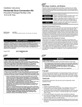
Unit Dimensions
Unit: inch (mm)
51.4 (1306) suspension position
41.0 (1040)
26.0 (660)
OD 1.26 (32)
46.8 (1188) air inlet duct flange
5.5 (140) x 8 = 44.1 (1120)
36.0 (914) suspension pos.
5.5 (140) x 8 = 44.1 (1120)
46.8 (1188) air outlet duct flange
48.9 (1240)
Discharge side
Suction side
25.5 (647)
23.6 (598)
1.4 (35)
1.8.5 (470)
15.2 (385)
E
F
D
A
C
B
A 3.9 (100) x 2 = 7.9 (200)
B 3.7 (93)
C 0.9 (22)
D 1.1 (29)
E
8.2 (209)
F 9.3 (236)
7
6
No. Item Description
1 Liquid pipe connection 3/8 (9.52)
2 Gas pipe connection
4TVA0076B100NB: 3/4 (19.05)
4TVA0096B100NB: 7/8 (22.22)
3 Drain pipe connection OD 1-1/4 (32), ID 1 (25)
4 Drain pipe connection (option drain pump) OD 1-1/4 (32), ID 1 (25)
5 Power supply/communication connection —
6 Air discharge flange —
7 Air suction flange —
8 Hook 3/8 in. or M10

8 VRF-SVX31A-EN
Preparing for Installation
Service Clearances
Note: If the unit is installed in a ceiling that does not have removable tiles, make allowances for
servicing the unit by creating an access hole. If the unit is installed more than 39.4 in. (1 m)
above the floor, the access hole must be the size of “B.” If the unit is installed less than
39.4 in. (1 m) above the floor, the access hole must be the size of “A” +“B” both.
Unit Insulation for High-Humidity Applications
For high-humidity applications, insulate the unit prior to mounting it. Use the following guidelines.
CAUTION
Avoid Contact with Fan Motor Blower!
Install the unit at least 7.54 ft (2.2 m) from the floor to avoid the possibility of contact with the
fan motor blower while cleaning the duct. Failure to follow this installation requirement could
result in minor to moderate injury.
Unit width (W)
A = W + 3.94 (100)
B = 19.7 (500)
0.78 (20)
0.78 (20)
Unit depth (D) + 1.97 (50)
Ceiling
Unit
A and B C and D Top and Bottom
48.8 x 18.5 (1240 x 470) 18.5 x 41.0 (470 x 1040) 48.8 x 41.0 (1240 x 1040)
Notes: Use an insulation thickness of at least 3/8 in. (10 mm).
Insulate the suction duct and discharge duct at the same time as the sides of the unit.
D
B
CA
Unit: inch (mm)

VRF-SVX31A-EN 9
Installation
Installation
Review “Installation Considerations” before proceeding with installation.
Follow the procedures in these sections in the order given.
Note: Install the Y-joint before installing the indoor unit.
Mounting the Unit
If the ceiling is already constructed, piping must be laid into position before placing the unit inside
the ceiling.
To mount the unit:
1. Place the template on the spot where the unit is to be installed and mark the holes.
Note: The template may shrink or stretch slightly due to heat or humidity. Before drilling holes,
verify proper dimensions between the marks.
2. Determine the appropriate type of suspension bolts and anchors according to the ceiling type.
Insert bolt anchors into existing ceiling supports (A) or construct a suitable support (B).
3. Install suspension bolts at all four locations.
4. Screw two nuts to each suspension b
olt, leaving space between the nuts for hanging the unit.
Note: If the suspension bolts are longer than 59 in.
[1.5 m]) or vibrations are a concern, place
isolators on the brackets to absorb vibrations.
5. Hang the unit by its support brac
ke
ts between the two nuts.
6. If pad stoppers or isolators are used to absorb vibrations, place them on the brackets.
7. Tighten the nuts to suspend
the unit following th
e guidelines in the figure below.
CAUTION
Avoid equipment damage and personal injury!
Ensure that the ceiling is strong enough to support the weight of the indoor unit. Before
hanging the unit, test the strength of each of the attached suspension bolts.
A
B
Ceiling support
Concrete
Pre-poured
anchor
Drill hole for
anchor
Field-supplied suspension
bolts (M10 or 3/8 in.)
Isolator
Bracket
Washers, isolators, or spacers
Threaded rod should not protrude more than
1.2 in (30 mm) below the top of the bracket

10 VRF-SVX31A-EN
Installation
8. Maintain proper spacing between the unit and the ceiling; refer to the following figure.
9. Adjust the level of the unit so that it tilts1° to the side of the unit that will be connected to the
drain hose. A tilt of 1°is also recommended when a drain pump is installed.
Purging the Unit
The unit is shipped from the factory with a holding charge of nitrogen. All of this gas must be
purged from the unit.
To purge the unit, remove the caps from the ends of both gas and liquid refrigerant pipes. Make
sure all gas has escaped before connecting the piping.
Note: To prevent dirt or foreign objects from getting into the pipes during installation, do not
remove the caps completely until you are ready to connect the piping.
Ceiling
0.78 (20)
0.78 (20)
Unit
Drain hose port
1°
Liquid refrigerant port
Gas refrigerant port
Wet cloth
Welding flame

VRF-SVX31A-EN 11
Installation
Installing Refrigerant Piping
Connect field-supplied piping using flared connections (not supplied) or by brazing. The large unit
port is for gas refrigerant; the small one is for liquid refrigerant.
Cut or extend field-supplied piping as needed. Use the following procedures.
• Before connecting the pipes, make sure they are free of dirt and debris.
• Use insulated, unwelded, degreased, and deo
xidized copper pipe (Cu-DHP type according to
ISO 1337 or UNI EN 12735-1) suitable for an operating pressure of at least 609.15 psi (4200 kPa)
and a burst pressure of at least 3002.28 psi (20,700 kPa). Copper pipe for hydro-sanitary
applications
is unsuitable.
• For sizing and limits (height difference, line length, m
aximum bends, refrigerant charge, and
so on) see the outdoor unit installation manual.
• All refrigerant connections must be accessible for servicing an
d maintenance.
Pipe Cutting
Required tools:
•Pipe cutter
•Reamer
• Pipe holder
1. Using a pipe cutter, cut the pipe so that the cut edge is at 90° to the side of the pipe.
2. Use a reamer to remove all burrs at the cut edge.
See examples of correctly and incorrectly cut pipes.
Flared Pipe Connections
Clutch type and wing nut type flare tools are available for flared pipe connections.
1. Slide the flare nut over the pipe to be flared.
2. Slide the end of the pipe into the h
ol
e on the flaring bar that fits the pipe, leaving a length of
pipe, determined by tool type (see table), extending above the flaring bar. Clamp it down.
NOTICE
System Failure!
If brazing is used for pipe connections, a nitrogen purge is required to prevent the formation of
copper oxides inside the piping. Failure to follow this procedure could damage the system.
Correct: 90º
Oblique
Rough
Burr
Length of pipe extending above flare bar
Pipe
Flaring
bar

12 VRF-SVX31A-EN
Installation
3. Attach the yoke to the flaring bar, centering the conical part over the end of the pipe that is
extending above the flaring bar.
4. Tighten the yoke securely to flare the end of the pipe.
5. Remove the pipe. The end of the pipe that you flared sh
ould lo
ok like the end of a trumpet. See
examples of correctly and incorrectly flared pipes.
6. Align the pipes and tighten the flare nuts manually and then with a spanner torque wrench,
applying the torque according to pipe dimensions:
R-410A clutch type
Conventional flare tool
Clutch type Wing nut type
0–0.020 in. 0.04–0.06 in. 0.06–0.08 in.
Outer diameter
(in. [mm])
Connection
torque (ft·lb)
Flare
dimension
(in.)
Flare shape (in.)
1/4 (6.35) 10.3–13.3 ft·lb 0.34–0.36
3/8 (9.52) 25.1–31.0 ft·lb 0.50–0.52
1/2 (12.70) 36.1–45.0 ft·lb 0.64–0.65
5/8 (15.88) 50.2–60.5 ft·lb 0.76–0.78
Yoke
Flaring bar
Copper pipe
Flare nut
Inclined
Damaged
surface
Uneven
thickness
Correct
Cracked
R.016–.031
45°±2°
90°±2°

VRF-SVX31A-EN 13
Installation
Leak Testing Pipe Connections
Notes:
• All required piping pressure tests must be completed in accordance with national and/or
local codes.
• When leak-testing refrigerant systems, observe all safety precautions.
• Leak test only one circuit at a time to minimize system exposure to potentially harmful
moisture in the air.
• Use R-410A refrigerant gas as a tracer for leak detection and use oil-pumped dry nitrogen
to develop required test pressures.
1. Close liquid line angle valve.
2. Connect R-410A refrigerant cylinder to
high side charging port (at condenser or field supplied
discharge line access port). Add refrigerant to reach pressure of 12 to 15 psig.
3. Disconnect refrigerant cylinder. Connect dry n
itrogen cylinder to high side charging port and
increase pressure to 150 psig. Do not exceed high side (discharge) unit nameplate design
pressure. Do not subject low side (suction) components to high side pressure.
4. Check all piping joints,
valves, et
c. for leaks. Recommend using electronic detector capable of
measuring 0.1 oz/year leak rate.
5. If a leak is located, use proper procedures to remove the refrigerant/nitr
ogen mixture, break
connections and make repairs. Retest for leaks.
6. Make sure all service valves are open.
WARNING
Confined Space Hazards!
Do not work in confined spaces where refrigerant or other hazardous, toxic or flammable gas
may be leaking. Refrigerant or other gases could displace available oxygen to breathe, causing
possible asphyxiation or other serious health risks. Some gases may be flammable and or
explosive. If a leak in such spaces is detected, evacuate the area immediately and contact the
proper rescue or response authority. Failure to take appropriate precautions or to react properly
to such potential hazards could result in death or serious injury.
WARNING
Explosion Hazard!
Never use an open flame to detect gas leaks. It could result in an explosion. Use a leak test
solution for leak testing. Failure to follow recommended safe leak test procedures could result
in death or serious injury or equipment or property-only-damage.
Use only dry nitrogen with a pressure regulator for pressurizing unit. Do not use acetylene,
oxygen or compressed air or mixtures containing them for pressure testing. Do not use
mixtures of a hydrogen containing refrigerant and air above atmospheric pressure for pressure
testing as they may become flammable and could result in an explosion. Refrigerant, when
used as a trace gas should only be mixed with dry nitrogen for pressurizing units. Failure to
follow these recommendations could result in death or serious injury or equipment or
property-only damage.
Do not exceed unit nameplate design pressures when leak testing system. Failure to follow
these instructions could result in an explosion causing death or serious injury.

14 VRF-SVX31A-EN
Installation
Installing the Drain System
1. Push the supplied drain hose as far as possible over the drain hose port.
• Do not apply excessiv
e force to the piping on the unit side when connecting the drain hose.
• Drain hose port locations differ depending on the unit type.
2. Wrap the insulation (supplied) around the drain hose and clamp the connection as tightly as
possible until you can see at least 8 holes.
3. Install the drain pipe into the drai
n hose. Secure it with PVC adhesive and clamps as necessary
to ensure a tight fit with no leakage.
Drain hose port
Drain hose
Drain hose port
Insulation
Clamp
Drain hose
PVC pipe

VRF-SVX31A-EN 15
Installation
4. Refer to appropriate figure for installing the drain pipe with out without a drain pump.
Hanger
Unit: in. (mm)
Ceiling
Air vent
Flexible hose
39.4–59
(1000–1500)
7.87 (200)
0.79 (20)
11.8
(300)
Note: Install a U-trap at the end of the
drain pipe to prevent odors.
Drain pipe installation with drain pump
Drain pipe installation without drain pump
Hanger
39.4–59
(1000–1500)
Unit: in. (mm)
H2 (50)
1/2H
Horizontal drain pipe minimum slope: 1/100 slope
Ceiling
Flexible hose

16 VRF-SVX31A-EN
Installation
Centralized Drainage
If the installation requires more than three indoor units, install the main air vent at the front of the
indoor unit that is farthest from the main drain. It may be necessary to install individual air vents
to prevent water flowing back to each indoor unit.
For installations without a drain pump, install U-traps at the end of the drain pipe for each unit.See
figures below.
Hanger
Main drain pipe
Individual
air vent
Main air vent
Centralized horizontal drainpipe (more
than 1/100 slope)
13 in. (330 mm)
maximum
39–59 in. (1–1.5 m)
Ceiling
Drain pipe installation with drain pump
3.94 in. (100 mm) minimum
Ceiling
Drain pipe installation without drain pump

VRF-SVX31A-EN 17
Installation
Testing the Drainage
After completing the installation, test the drainage to make sure there are no leaks:
1. Operate the unit in cool mode.
2. Remove drain pump cover.
3. Squirt water into the d
rai
n pan (see figure).
4. Confirm that the water flows out through the drain hose and that no leakage occurs at any of
the connections.
5. Reassemble the drain pump cover.

18 VRF-SVX31A-EN
Insulation
Insulation
After determining that there are no leaks in the refrigerant pipes or drainage hose, insulate them
as described in these sections.
Refrigerant Pipes
1. Use the table below to select the insulation type for each pipe size.
2. Wrap insulation around the entire surface of each pipe, from the indoor unit to the outdoor unit,
overlapping insulation to avoid gaps. Clamp insulation tightly to pipe.
• Do not wrap the gas and liquid refrigerant pipes together.
• Avoid compressing the insulation as much as possible.
• Be sure there are no cracks or deformities in the insulation at bends in pipes.
• If necessary double the insulation to prevent condensation from forming in warm or humid
areas.
• Cut off excess insulation.
Drainage Hose
Insulate (field supplied) the entire surface of the drain pipe that is inside the building, including the
connection between the drain hose and drain stub. Clamp tightly.
Pipe
Pipe size
(in. [mm])
Insulation Type
Standard conditions
(86°F [30°C], 85%)
High humidity conditions
(a)
(86°F [30°C], over 85%)
EPDM or NBR
Liquid pipe
1/4 (6.35) – 3/8 (9.52) 3/8 (9) 3/8 (9)
1/2 (12.70) – 2 (50.80) 1/2 (13) 1/2 (13)
Gas pipe
(b)
1/4 (6.35) 1/2 (13) 3/4 (19)
3/8 (9.52) – 1 (25.40)
3/4 (19)
1.0 (25)
1-1/8 (28.58) – 1-3/4 (44.45) 1-1/4 (32)
2 (50.80) 1.0 (25) 1-1/2 (38)
(a)When installing insulation in any of the following environments, use insulation required for high humidity conditions: Buildings with close proximity to
bodies of water or hot springs or on the side of a hill in which the building is partly covered by earth; ceilings frequently exposed to moisture such as
in restaurants, saunas, swimming pools, and corridors of dormitories or studios near a frequently-used outdoor exit; buildings with no ventilation system.
(b) Internal temperature of gas pipe is higher than 248°F (120°C).

VRF-SVX31A-EN 19
Wiring the Unit
Wiring the Unit
Observe the following precautions when making electrical connections.
• Make all electrical connections in accordance with electrical codes and ordinances.
• Select the power cable in accordance with relevant local and national regulations.
• Wire size must comply with local and national code.
• Use grade H07RN-F or H05RN-F power cable.
• Connect the power cable into the power cable terminal and fasten it with a clamp.
• Unbalanced power must be maintained within 10% of supply rating among whole indoor units.
• Significantly unbalanced power may shorten the life of the system. If the unbalanced power is
greater than 10% of supply rating, the unit will stop and an error code will be generated.
• Connect the power cable to the auxiliary circuit breaker. An all-pole disconnection from the
power supply must be incorporated in the fixed wiring (1/8 in. [3 mm]).
• All wiring must be protected from weather and damage.
• Maintain a distance of 2 in. (50 mm) or more between power and communication cables to
prevent interference.
• Maintain a voltage drop of less than 10% between the power source and the unit(s).
• Use an appropriate screwdriver for tightening the terminal screws. A screwdriver with a small
head will strip the head and make proper tightening impossible.
• Over-tightening the terminal screws may break them.
Tightening torque for M4 screws: 0.86–1.06 lbf·ft (12.0–14.7 kgf·cm).
• After making a knockout hole, apply rust-preventive paint to the bare metal around the hole.
• Secure the cable conduit to the outdoor knockout using the proper connector and bushing.
Power
Connect the power cable to terminals 1(L) and 2(N) on each indoor unit. Refer to wiring diagram.
Communication
If installing a wired remote control, connect the communication cable to terminals F3 and F4. Refer
to Figure 1.
Electronic Expansion Valve (EEV) Kit
EEV kits are required for high-wall and convertible units. Refer to the Figure 1.
WARNING
Hazardous Voltage!
Disconnect all electric power, including remote disconnects before servicing. Follow proper
lockout/tagout procedures to ensure the power can not be inadvertently energized. Failure to
disconnect power before servicing could result in death or serious injury.
NOTICE
Use Copper Conductors Only!
Unit terminals are not designed to accept other types of conductors. Failure to use copper
conductors could result in equipment damage.

20 VRF-SVX31A-EN
Wiring the Unit
Figure 1. Wiring diagram
1(L)
2(N) F2
F1 1(L)
1(L)
2(N)
2(N)
F1F1
F2
F2
F4F3
F3 F4
208–230 V
F1
F2
NLNLNL
NL
F1
F2
F1
F1
F1
F2
F2 F2
1(L)
2(N) F2
F1
1(L)
2(N) F2
F1 1(L)
2(N)
F2
F1
Wired remote
control
Outdoor unit
Indoor unit 1
Indoor unit 2 Indoor unit 3
EEV kit
Indoor unit 4
Indoor unit 5 Indoor unit 6
/