Page is loading ...

06-199 MAY 2020
VORTEX
ASSEMBLY AND INSTALLATION
INSTRUCTIONS
SRS AUSTRALIA, PTY LTD
12 Enterprise St
Richlands QLD 4077
Australia
Phone 07 3812 2283 • Fax 07 3812 1187
www.srsmith.com/au
S.R. SMITH, LLC
CORPORATE HEADQUARTERS
P.O. Box 400 • 1017 S.W. Berg Parkway
Canby, Oregon 97013
USA
Phone (503) 266 2231 • Fax (503) 266 4334
www.srsmith.com
S.R. SMITH VORTEX SLIDES ARE MANUFACTURED FOR INSTALLATION
AND USE ON INGROUND SWIMMING POOLS ONLY. THE VORTEX IS
NEVER TO BE INSTALLED AND USED ON ABOVEGROUND POOLS,
ONGROUND POOLS, HOUSEBOATS, BOAT DOCKS, FLOATING DOCKS
OR PLATFORMS OR OTHER BODIES OF WATER SUCH AS LAKES,
PONDS, RIVERS, ETC.

2
TABLE OF CONTENTS
INTRODUCTION ........................................................................................................................................... 3
INSTALLED VORTEX STRUCTURAL & INSTALLATION CHECKLIST ..................................................... 4
MAINTENANCE INSTRUCTIONS ................................................................................................................ 4
ASSEMBLED VORTEX WITH STAIRS LAYOUT......................................................................................... 5
ASSEMBLED VORTEX WITH LADDER LAYOUT ....................................................................................... 5
MAIN SECTION AND SLIDE RUNWAY PARTS LIST ................................................................................. 7
Tools Required .......................................................................................................................................... 8
Gasket Installation ..................................................................................................................................... 8
VORTEX MAIN SECTION AND SLIDE RUNWAY ASSEMBLY INSTRUCTIONS ...................................... 9
VORTEX CLOSED FLUME PARTS LIST ................................................................................................... 14
VORTEX CLOSED FLUME ASSEMBLY INSTRUCTIONS ........................................................................ 15
VORTEX OPEN FLUME PARTS LIST ....................................................................................................... 18
VORTEX OPEN FLUME ASSEMBLY INSTRUCTIONS ............................................................................ 19
VORTEX STAIRWAY PARTS LIST ............................................................................................................ 22
VORTEX STAIRWAY ASSEMBLY INSTRUCTIONS ................................................................................. 23
VORTEX LADDER PARTS LIST ................................................................................................................ 32
VORTEX LADDER ASSEMBLY INSTRUCTIONS ..................................................................................... 33
VORTEX WARNING SIGN PARTS LIST ................................................................................................... 35
VORTEX WARNING SIGN ASSEMBLY INSTRUCTIONS ........................................................................ 36
VORTEX WATER SYSTEM PARTS LIST .................................................................................................. 37
WATER SYSTEM ASSEMBLY INSTRUCTIONS ....................................................................................... 37
CONCRETE WEDGE ANCHOR MOUNTING INSTRUCTIONS ................................................................ 41
MANUFACTURER’S PLACEMENT INSTRUCTIONS ............................................................................... 42
Visit srsmith.com for information on the complete line of
S.R. Smith pool products.
SLIDE ASSEMBLY AND INSTALLATION VIDEOS AVAILABLE AT
www.youtube.com/srsmithllc
REGISTER YOUR S.R. SMITH PRODUCT AT
http://www.srsmith.com/en-us/customer-service/product-registration

3
INTRODUCTION
DANGER – FAILURE TO FOLLOW THESE WARNINGS, INSTRUCTIONS, AND THE
OWNER’S MANUAL MAY RESULT IN SERIOUS INJURY OR DEATH.
THE VORTEX IS DESIGNED AND MANUFACTURED FOR INSTALLATION AND USE ON INGROUND
SWIMMING POOLS ONLY. DO NOT INSTALL THIS SLIDE ON ABOVEGROUND POOLS,
HOUSEBOATS, BOAT DOCKS, FLOATING DOCKS OR PLATFORMS, OR OTHER BODIES OF
WATER SUCH AS LAKES, PONDS, RIVERS, ETC. PROPER ASSEMBLY, INSTALLATION, USE,
AND SUPERVISION ARE ESSENTIAL FOR PROPER OPERATION AND TO REDUCE THE RISK OF
SERIOUS INJURY OR DEATH.
ALL NATIONAL AND LOCAL BUILDING CODES MUST BE FOLLOWED. THIS INCLUDES ANY
APPLICABLE REQUIREMENTS FOR SIZE OF CONCRETE FOOTING, OVERALL HEIGHT OF SLIDE,
AND BONDING OR ELECTRICAL CODES.
CHECK INSIDE ALL BOXES AND PACKAGING MATERIALS FOR PARTS. BEFORE BEGINNING
ASSEMBLY, READ ALL INSTRUCTIONS AND IDENTIFY PARTS USING THE FIGURES AND PARTS
LISTED IN THIS DOCUMENT. IT IS CRITICAL THAT ALL PARTS BE CAREFULLY INSPECTED BY
THE INSTALLER PRIOR TO INSTALLATION TO ENSURE THAT NO DAMAGE OCCURRED IN
TRANSIT AND THAT A DAMAGED PART IS NOT USED. PROPER INSTALLATION CANNOT BE
OVERSTRESSED. IMPROPER INSTALLATION VOIDS THE S.R. SMITH WARRANTY AND MAY
AFFECT THE SAFETY OF THE USER.
PRECAUTION: POWDER COATING IS SCRATCH RESISTANT, NOT SCRATCH PROOF. IT IS STILL
SUSCEPTIBLE TO SCRATCHING AND CHIPPING. THIS SHOULD BE PREVENTED BECAUSE
EXPOSED METAL SURFACES WILL RUST.
PRECAUTION: CONTACT YOUR POOL PROFESSIONAL TO MAKE SURE THAT YOU HAVE
ADEQUATE ACCESS TO YOUR POOL PUMP HOUSE FOR THE WATER SUPPLY. IT IS STRONGLY
RECOMMENDED THAT THE WATER LINE BE PULLED FROM THE SWIMMING POOL RETURN
LINE SO THAT THE CIRCULATED WATER IS SANITARY AND DOES NOT AFFECT THE
CHEMISTRY OF THE POOL.
INSTALLER MUST GIVE TO SLIDE OWNER: VORTEX SLIDE INSTALLATION AND OWNER’S
MANUAL, THE WARRANTY CARD, AND ANSWER ALL QUESTIONS REGARDING SAFE AND
PROPER USE AND SLIDE MAINTENANCE.
WARNING SIGN MUST BE MOUNTED NEAR SLIDE ENTRANCE. SIGN SHOULD BE LOCATED
WITHIN 2 FEET OF THE ENTRANCE OF THE SLIDE AND MUST POINT AWAY FROM ENTRANCE
SO THAT IT IS VISIBLE AT LEAST 10 FEET FROM SLIDE.
FOR COMPLETE SLIDE SAFETY INFORMATION REFER TO THE OWNER’S MANUAL.

4
INSTALLED VORTEX STRUCTURAL & INSTALLATION CHECKLIST
Installer to review this checklist with slide’s owner upon completion of slide installation.
1. Inspect the runway for visible cracks or tears.
2. Inspect the ladder for sharp edges, protrusions, cracks, or tears.
3. Inspect all fasteners to make sure they are fully tightened.
4. Inspect the ladder for structural stability.
5. Measure the following dimensions and compare with the manufacturer’s placement instructions listed
on pages 41 and 41.
• Measure the depth of water in front of the slide exit. (4’-6” min. Depth at a distance of 4’-6” from
exit end of slide.)
• Measure the height of the slide runway exit above the water. (20” max.)
• Measure the distance between the centerline of the slide and the edge of other pool equipment.
6. Observe the position of the exit of the slide as shown on pages 41 and 41.
MAINTENANCE INSTRUCTIONS
1. Periodically inspect the vortex to assure there are no worn parts and that all hardware is properly
tightened. Replace any hardware which exhibits rust or corrosion.
2. All slide components require periodic maintenance. Clean components with a cotton cloth and a non-
abrasive soap and water. Avoid harsh chemicals and disinfectants.
3. Always read the label instructions on any cleaner carefully before applying it to a surface.
4. Inspect the plumbing system for leaks. Freeze/thaw cycles may cause leaks at plumbing joints which
should be repaired prior to use.
5. Check all safety labels to insure they have not peeled or been removed. Contact S.R. Smith customer
service (800-824-4397) for replacement labels.
6. The support structure is made from steel, is primed and powder coated with a high quality acrylic
urethane finish. However, corrosion may occur depending on water chemistry and environmental
conditions. Inspect the slide on a semi-annual basis, sand and repair any surface rust. For touch-up
paint (PN # 09-819-1), contact S.R. Smith customer service (800-824-4397).
CAUTION:
BECAUSE THIS PRODUCT IS MANUFACTURED FROM STEEL, PLACEMENT ON A POOL WITH A
SALT CHLORINE GENERATOR WILL REQUIRE FREQUENT INSPECTION AND MAINTENANCE
DUE TO THE CORROSIVE NATURE OF THESE SYSTEMS WITH ALL STEEL ALLOYS. IT IS
RECOMMENDED THAT ALL SLIDE COMPONENTS BE RINSED DAILY WITH FRESH WATER.

5
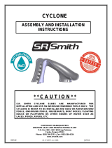
ASSEMBLED VORTEX WITH STAIRS LAYOUT
FIGURE A

6
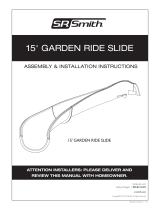
ASSEMBLED VORTEX WITH LADDER LAYOUT
FIGURE B

7
MAIN SECTION AND SLIDE RUNWAY PARTS LIST
Visit srsmith.com for hardware kit and replacement part information.
ITEM NO.
PART NO.
DESCRIPTION
QTY.
KIT A
KIT B
KIT C
KIT A
66-209-177
FLUME HARDWARE KIT
1 ea.
KIT B
66-209-178
HALF FLUME HARDWARE KIT
1 ea.
KIT C
66-209-311
UNIVERSAL SPARE HARDWARE KIT
1 ea.
1
6-690-1
ENTRANCE SECTION
1 ea.
2
6-690-2
RUNWAY SECTION
4 ea.
3
6-690-3
EXIT SECTION
1 ea.
4
14-301
BRANCH ARM
5 ea.
5
14-300
MAIN SUPPORT
1 ea.
6
14-205
EXIT SUPPORT
1 ea.
7
5-113
3/8” x 2” HHCS S/S
2 ea.
●
●
8
05-32-131
3/8” x 5-1/2” HHCS
8 ea.
●
●
9
5-523
1/2” x 3-3/4” CONC. ANCHOR W/ HARDWARE
12 ea.
●
●
10
5-250
3/8” x 3-1/2” BHCS S/S
2 ea.
●
●
11
5-512
3/8” x 4” BHCS S/S
8 ea.
●
●
12
5-237
3/8” x 5” BHCS S/S
4 ea.
●
●
13
5-524-SS
1/2” x 5” HHCS S/S
5 ea.
●
●
14
VULKEM-116
VULKEM GRAY SEALANT
1 ea.
15
05-14-132
1/2” x 1-3/8” FLAT WASHER S/S
10 ea.
●
●
●
16
05-14-115
1/2” LOCK WASHER S/S
17 ea.
●
●
●
17
05-14-116
1/2” HEX NUT S/S
5 ea.
●
●
●
18
05-14-107
3/8” x 1” FLAT WASHER S/S
16 ea.
●
●
●
19
05-616
1/2” NYLON WASHER
22 ea.
●
●
●
20
05-32-111
3/8” NYLON WASHER
18 ea.
●
●
●
21
5-145
3/8” x 7/8” FLAT WASHER S/S
34 ea.
●
●
●
22
5-151
3/8” LOCK WASHER S/S
30 ea.
●
●
●
23
5-139
3/8” HEX NUT S/S
26 ea.
●
●
●
24
5-521
3/8-16 x 3” CONC. ANCHOR W/ HARDWARE
2 ea.
●
●
25
8-536
1/2” WIDE x 1/3” TALL RUBBER GASKET
21 ft.
26
14-203
RIGHT GUARD RAIL
1 ea.
27
14-204
LEFT GUARD RAIL
1 ea.
68
05-237
HDPE GASKET FOR EXIT SUPPORT
1 ea.
69
05-234
HDPE GASKET FOR MAIN SUPPORT
1 ea.
75
05-618
1/2” NUT CAP - GRAY PLASTIC
12 ea.
76
05-608
3/8” x 1” NUT CAP - BLACK RUBBER
2 ea.

8
Tools Required
1. Ratchet Handle
2. 9/16” Socket (Deep)
3. 9/16” Wrench
4. 3/4" Socket or Wrench (Deep)
5. 7/32” Allen Wrench (Deep)
6. Phillips Head Screwdriver
7. Roto-Hammer Drill
8. 1/4" Drill Bit for Step Assy.
9. 1/2" Concrete Drill Bit
10. 3/8” Concrete Drill Bit
11. 4” Ratchet Extension
12. 4 Irwin Quick Grip™ 18” XP Bar Clamps
13. Power Drill
14. PVC Pipe Primer & Glue
15. Anti-Seize
16. Saw to Cut PVC Pipe
17. Knife
18. Level
19. Hammer
20. 8’ Step Ladder
21. Rubber Mallet
22. Torque Wrench
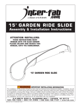
Gasket Installation
• The gasket material has been installed at the factory, however additional gasket has been
provided in case any gasket has fallen off during shipping. If gasket installation is required, follow
the instructions below.
• Apply gasket in the required locations as shown in the figures below.
• Place gasket along the section to determine the length needed.
• Cut gasket to appropriate length.
• Remove backing and adhere gasket to slide.
FIGURE C

9
VORTEX MAIN SECTION AND SLIDE RUNWAY ASSEMBLY INSTRUCTIONS
1. Insert all five of the Branch Arms (4) into the Main Support (5). Carefully slide the arms into the
support sockets to ensure the powder coating is not damaged. Align the holes in the branch arms
with the slots in the main tube support and fasten them as shown in Figure D.
The required hardware is as follows: 1/2”–13 x 5” Hex Head Cap Screw (13), 1/2” Flat Washer (15),
1/2” Nylon Washer (19), and 1/2” Nylon Washer (19), 1/2” Flat Washer (15), 1/2” Lock Washer (16),
1/2” Hex Nut (17) on the other side of the support.
ANTI-SEIZE NEEDS TO BE USED ON ALL BOLTS, and should be applied to the threads before
attempting to place the nut on the bolt.
Note: It is important to NOT TIGHTEN the hardware at this point.
Place the column near the installation location.
FIGURE D

10
FIGURE E
Note: Before working with the flume pieces, cover the concrete with cardboard or carpet to
prevent scratching the plastic slide components.
The order of assembly is important!
All of the Runway Sections (2) are labeled at both ends indicating the order in which they need
to be assembled.
2. Assemble the Exit Flume (3) and the Runway Section (2) as shown in Figure E. Make sure that the
Runway Section (2) that you are installing is labeled B1 on one end and B2 on the other. Install the
hardware through both side rails. The required hardware is as follows: 3/8”-16 x 4” Button Head Cap
Screw S/S (11), 3/8” Flat Washer (21), 3/8” Flat Washer (21), 3/8” Lock Washer (22), 3/8” Hex Nut
S/S (23). Tighten the hardware until snug.
3. Turn the two previously connected flume parts upside down. Attach the Exit Support (6) to the Exit
Flume (3), as shown in Figure F. The required hardware is as follows: 3/8”-16 x 2” Hex Head Bolt
(7), 3/8” Flat Washer (21) on the outside and 3/8” Nylon Washer (20), 3/8” Flat Washer (21), 3/8”
Lock Washer (22), 3/8” Hex Nut (23) on the inside. Tighten the hardware until snug.
Note: Apply anti-seize to all fasteners to prevent galling.
FIGURE F

11
4. Place the assembled Exit Flume (3) and Runway Section (2) over the first Branch Arm (4). Attach the
slide sections to the first branch arm as shown in Figure G. The required hardware is as follows: 3/8”-
16 x 5-1/2” Hex Head Cap Screw (8), 3/8” Flat Washer (18), 3/8” Nylon Washer (20), 3/8” Flat
Washer (18), 3/8” Lock Washer (22), and a 3/8” Hex Nut (23).
Note: Do not completely tighten the hardware at this point. Be sure to apply anti-seize to all
fasteners to prevent galling.
5. With the Exit Flume (3) and Runway Section (2) connected to the branch arm (4), position the slide
exit in accordance with the Manufacturer’s Placement Instructions listed on page 41 and 41.
Temporarily place bolts through the other end of Runway Section (2) into the second branch arm to
ensure proper alignment. Once the assembly is in the correct position, mark the locations for the
main support and the exit support anchors. Move the assembly aside then drill 1/2”Ø x 4” deep holes
for the Main Support (5) concrete wedge anchors and 3/8”Ø x 4” deep holes for the Exit Support (6)
concrete wedge anchors. Move the assembly back into place, with the HDPE Gaskets (68) and (69)
between the base plates and deck. Then install the wedge anchors in accordance with the
instructions on page 41.
The required hardware for the Main Support (5) anchors is as follows: 1/2” Wedge Anchor with
hardware (9), 1/2” Nylon Washer (19), 1/2” Lock Washer (16), Nut Cap (75). See Figure H for order
of assembly.
The required hardware for the Exit Support (6) anchors is as follows: 3/8” Wedge Anchor with
hardware (24), 3/8” Nylon Washer (20), 3/8” Lock Washer (22), Nut Cap (69). See Figure H for order
of assembly.
FIGURE G
FIGURE H

12
6. Fasten the sides of Runway Section (2) labeled B2 to the previously assembled runway section using
the fasteners shown in Figure E. Then attach the bottom of Runway Section (2) to the branch arm
using the fasteners shown in Figure G.
7. Repeat this process for the three remaining Runway Sections. Remember that order of assembly
is important. The end of each runway section is labeled and must be assembled to the runway
section with the same label.
Assembly Tip: It is recommended that Irwin Quick Grip bar clamps be used to help align the
fastener holes in the runway sections.
8. Attach the Entrance Section (1) to the last Runway Section (2). Fasten the sides of the Entrance
Section (1) as shown in Figure I. The hardware required is as follows: 3/8”-16 x 5” Button Head Cap
Screw S/S (12), 3/8” Flat Washer S/S (21), 3/8” Flat Washer S/S (21), 3/8” Lock Washer S/S (22),
3/8” Hex Nut S/S (23).
FIGURE I

13
9. Fasten the bottom of the Entrance Section (1) to the branch arm, as shown in Figure I. The screws
will be screwed into the threaded inserts in the Entrance Section (1). The hardware required is as
follows: 3/8”-16 x 3-1/2” Button Head Cap Screw S/S (10), 3/8” Lock Washer S/S (21), 3/8” Flat
Washer S/S (22), and a 3/8” Nylon Washer (20).
Note: Be sure to apply anti-seize to all fasteners to prevent galling.
After you have started all of these bolts, go back through and tighten all of the fasteners
installed up to this point.
Apply the 1/2” wide X 0.3” tall gasket to the top runway parts along the outside curve edge only. The
gasket should be applied on the mating surface, between the bolt holes and the inside edge of the
part.
10. Insert the Left Guard Rail (26) and the Right Guard Rail (27) into the two sockets on the top of the
Entrance Section (1), as shown in Figure J, so that the threaded stud ends come through the slide
side rails.
The hardware required to secure the studded Guard Rail legs are as follows: 3/8” Flat Washer (21),
3/8” Lock Washer (22), and a 3/8” Hex Nut (23). After all hardware has been attached tighten
each bolt securely.
Fasten the following hardware to attach the guardrail feet to the entrance section: 3/8” x 5” Button
Head Cap Screw,(12), 3/8” Flat Washer (21), 3/8” Nylon Washer (20), 3/8” Nylon Washer (20), 3/8”
Flat Washer (21), 3/8” Lock Washer (22), and a 3/8” Hex Nut (23). Do not fully tighten the nuts yet
because the fasteners will need to be removed later when installing the ladder or stairway.
Note: Be sure to apply anti-seize to all fasteners to prevent galling.
FIGURE J

14
VORTEX CLOSED FLUME PARTS LIST
Visit srsmith.com for hardware kit and replacement part information.
ITEM NO.
PART NO.
DESCRIPTION
QTY.
KIT A
KIT A
66-209-177
FLUME HARDWARE KIT
1 ea.
2
6-690-2
RUNWAY SECTION
4 ea.
●
11
5-512
3/8” x 4” BHCS S/S
14 ea.
●
12
5-237
3/8” x 5” BHCS S/S
22 ea.
●
18
05-14-107
3/8” x 1” FLAT WASHER S/S
66 ea.
●
22
5-151
3/8” LOCK WASHER S/S
54 ea.
●
23
5-139B
3/8”-16 HEX NUT S/S
52 ea.
●
35
5-518
3/8” x 6” BHCS S/S
2 ea.
●
36
5-516
3/8” x 8-1/2” HHCS S/S
4 ea.
●
37
05-626
3/8” RUBBER WASHER
4 ea.
●
38
05-14-151
VORTEX SPACER, 5/8 X 2.75 304 SS TUBING
12 ea.
●
82
05-14-150
3/8” CUSTOM FLAT WASHER S/S
24 ea.
●

15
VORTEX CLOSED FLUME ASSEMBLY INSTRUCTIONS
1. Assemble the four remaining Runway Section (2) pieces. Order of assembly is important. The
end of each runway section is labeled and must be assembled to the runway section with the same
label.
Assemble the lower two sections. They are labeled T1 on their mating ends. Fasten the sections
together using the screw hole locations located at the sides and the top of the Runway Section (2) as
shown in Figure K.
The hardware required for the two side locations is as follows: 3/8”-16 x 4” Button Head Cap Screw
S/S (11), 3/8” Flat Washer S/S (18), 3/8” Flat Washer S/S (18), 3/8” Lock Washer S/S (22), 3/8” Hex
Nut S/S (23).
The hardware required for the top location is as follows: 3/8”-16 x 5” Button Head Cap Screw (12),
and a 3/8” Flat Washer S/S (18), 3/8” Flat Washer (18), 3/8” Lock Washer (22), 3/8” Hex Nut (23).
Follow the same procedure to finish assembling the remaining two sections. First, assemble the
Runway Sections (2) labeled T2, followed by the Runway Section (2) labeled T3.
Note: Be sure to apply anti-seize to all fasteners to prevent galling.
FIGURE K

16
2. Make sure the gasket is in place. Slide all four assembled parts of the cover flume up the slide
from the bottom. You will need 3-4 people to assist in getting it positioned correctly.
Attach the hardware at the top of the runway as shown in Figure L. The hardware required for this
step is as follows: 3/8”-16 x 6” Button Head Cap Screw S/S (35), 3/8” Flat Washer S/S (18), 3/8” Flat
Washer S/S (18), 3/8” Lock Washer S/S (22), 3/8” Hex Nut S/S (23).
Next, working from the top to bottom, fasten the flumes together along the outside edge as shown in
Figure 12. The required hardware is as follows: a 3/8”-16 x 5” Button Head Cap Screw S/S (12), 3/8”
Custom Flat Washer S/S (82), 3/8” Custom Flat Washer S/S (82), 5/8” 304 SS Spacer 2 3/4” (38),
3/8” Flat Washer S/S (18), 3/8” Lock Washer S/S (22), 3/8” Hex Nut S/S (23).
Tighten the hardware until the gap in the joint is closed.
Do not over tighten.
Note: Be sure to apply anti-seize to all fasteners to prevent galling.
FIGURE L

17
3. Fasten the top and bottom runway parts together along the inside curve as shown in Figure 13.
The hardware required for this step is as follows: a 3/8”-16 x 8-1/2” Hex Head Cap Screw S/S
(14), 3/8” Flat Washer S/S (21), 3/8” Rubber Washer (27), 3/8” Flat Washer S/S (21), 3/8” Lock
Washer S/S (25), 3/8” Hex Nut S/S (26). There are four locations where this step is repeated.
After you have started all of these bolts, you should go back through and tighten all of the
fasteners installed up to this point .
Note: Be sure to apply anti-seize to all fasteners to prevent galling.
FIGURE M

18
VORTEX OPEN FLUME PARTS LIST
Visit srsmith.com for hardware kit and replacement part information.
ITEM NO.
PART NO.
DESCRIPTION
QTY.
KIT B
KIT B
66-209-178
HALF FLUME HARDWARE KIT
1 ea.
12
5-237
3/8” x 5” BHCS S/S
13 ea.
●
18
05-14-107
3/8” x 1” OD FLAT WASHER S/S
42 ea.
●
20
05-32-111
3/8” NYLON WASHER
6 ea.
●
22
5-151
3/8” LOCK WASHER S/S
19 ea.
●
23
5-139
3/8” HEX NUT S/S
19 ea.
●
38
05-14-151
VORTEX SPACER, 5/8 X 2.75 304 SS TUBING
12 ea.
●
39
6-690-4
CURVE SECTION RISER
4 ea.
40
5-513
3/8” x 4-1/2” BHCS S/S
6 ea.
●
41
4-235
CURVE SECTION RISER BRACKET S/S
2 ea.
●
42
5-514
3/8” x 3/4” BHCS S/S
4 ea.
●
74
8-537
CCF-1-1/4”–14-20, BLACK PE PLUG
12 ea.
●
82
05-14-150
3/8” CUSTOM FLAT WASHER S/S
12 ea.
●

19
VORTEX OPEN FLUME ASSEMBLY INSTRUCTIONS
1. Assemble the four Curve Section Riser (39) pieces. Fasten the two sections together using the two
bolt locations through the side of the parts as shown in Figure N. The hardware required for the two
side locations is as follows: 3/8”-16 x 4-1/2” Button Head Cap Screw S/S (40), 3/8” Flat Washer S/S
(18), 3/8” Flat Washer S/S (18), 3/8” Lock Washer S/S (22), 3/8” Hex Nut S/S (23).
Follow the same procedure to finish assembling the remaining two sections together.
Do not fully tighten any of the hardware until all of the hardware has been assembled.
Do not over tighten. Be sure to apply anti-seize to all fasteners to prevent galling.
FIGURE N

20
2. Make sure the gasket is in place.
3. Slide all four pieces of the open flume up the slide from the bottom. Attach the hardware at the top of
the runway as shown in Figure O. Use the Riser Bracket (41) to secure the Open Flume Risers to the
Runway.
4. Connect the Bracket to the Runway Flume with a 3/8”-16 x 5” Button Head Cap Screw S/S (12), 3/8”
Flat Washer S/S (18), 3/8” Nylon Washer (20), 3/8” Flat Washer S/S (18), 3/8” Lock Washer S/S (22),
3/8” Hex Nut S/S (23).
Note: When installing the upper Riser Bracket, remove and reuse the existing hardware previously
installed during the main section installation. See Figure O. Add a Nylon Washer (20) to protect the
Riser Bracket’s powder coat finish.
5. Install a 3/8”-16 x 3/4” Button Head Cap Screw S/S (42), 3/8” Flat Washer S/S (18), and 3/8” Nylon
Washer (20) through the Riser Bracket (41) and the Open Flume Riser.
Do not fully tighten any of the hardware until all of the hardware has been assembled.
Do not over tighten. Be sure to apply anti-seize to all fasteners to prevent galling.
FIGURE O
/