Page is loading ...

-1-
-2-
-3-
-4-
1 Packing List
Please check the following items after unpacking, if any missing, please
contact your local dealer.
No. Items Quantity
1 Switch 1pc
2 Plug Connector 1pc
3 Quick Installation Guide 1 pc
2 Safety Information
Before performing an operation, read the following operation instructions
and precautions to be taken, and follow them to prevent accidents.
2.1 General Requirements
Only qualified and skilled personnel must install, configure, and
unmount the device. The device must not be disassembled.
When operating the device, obey the local safety regulations. The
safety precautions provided in the document are supplementary and
shall be in compliance with the local safety regulations.
When operating the device, in addition to the precautions (please see
the notes below), follow the specific safety instructions.
The installation and maintenance personnel need to understand the
basic safety precautions to be taken.
Do not block the ventilation while the device is running. Keep a
minimum distance of 5 cm from the ventilation to the walls or the other
objects that block the ventilation.
Do not operate the device in an area that exceeds the maximum
recommended ambient temperature of 75°C.
Do not place the device in the environment that has inflammable and
explosive air or fog. Do not perform any operation in this environment.
2.2 Electric Safety
Connect the unit only to DC power source that complies with the safety
extra-low voltage (SELV) requirements in IEC62368-1 based safety
standards.
Before touching the device or hand-operating parts, wear a grounded
electrostatic discharge (ESD) wrist strap. It can prevent the sensitive
components from damage by the static electricity in the human body.
2.3 Optical Safety
When handling optical fibers, do not stand close to, or look at the
optical fiber outletdirectly with unaided eyes.
Cutting and splicing fibers must be performed by the trained personnel
only.
Before cutting or splicing a fiber, ensure the fiber is disconnected from
the opticalsource. After disconnecting the fiber, use protecting caps to
protect all the optical connectors.
3 Product Introduction
3.1 Overview
The switch is Industrial 8-Port Gigabit PoE+ 4-Port SFP L2 Managed
Ethernet Switch.
This switch provides 8 Gigabit Ethernet RJ-45 ports and 4 Gigabit SFP
uplink ports. It meets IEEE 802.3af/at standard. All RJ-45 ports support
Power-over-Ethernet (PoE+) and deliver up to 30W power per port.
The switch has extensive L2 management functions, such as 802.1Q
VLAN, 802.1P QoS, STP/RSTP, Link aggregation, DHCP and PoE control.
It can be easily managed via a WEB GUI (http/https), CLI
(telnet/ssh/console) or SNMP.
3.2 Hardware Introduction
Front Panel
Side Panel
LED Indicators
Indicators Status Descriptions
P1 Indicator of
Power 1 On Power 1 is on.
Off Power 1 is off.
P2 Indicator of
Power 2 On Power 2 is on.
Off Power 2 is off.
RUN System
indicator Blink The system is working normally.
On/Off The system failure
Console Port
The device contains a serial RS-232 interface as the console port for local
management interface. For the console port, a standard RJ-45 connector
is used. Use a RS-232 calbe (Sub-D9 to RJ-45) to connect the console
port with the COM port of a PC.
See the default configuration in chapter “6 Factory Settings”.
Init Button
The init button has two operating modes.
By short pressing the button, the switch will be reset and the
configuration is as previous setting saved.
By pressing the button over 5s, the switch will be restored to the
original factory default setting.
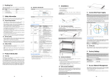
4 Installations
The switch suppoorts DIN-rail installation.
Dimensions (mm)
The DIN-rail hanger is fixed on the switch at the facory. Please Install the
switch to the DIN rail directly.
Install the switch to the DIN rail.
5 Connect the Power Supply
Note:
The equipment is intended to be grounded to comply with emission and
immunity requirements. Ensure that the switch functional ground screw is
connected to earth ground during normal use.
Use one end of GND cable to connect the M3 grounding connector of the
switch, the other end to a ground point. The GND of the switch is shorted
to the copper protection ground bar provided by the user. The GND cable
used is recommended to be plastic insulating one with copper core, with
cross-sectional area greater than 1.5mm².
Ground the switch housing
The switchis powered by a DC power connection. It supports redundant
power supply.
It is possible to connect a second power source using the same voltage
with the redundant power supply port. If one source fails, the alternative
source takes over the power supply without interruption.
5.1 DC Supply
The power supply connectors are equipped with 6-pin plug connectors (2
NC pins in the middle of the connector). Please observe the polarity.
Use DC power cable to connect positive/negative wires of DC power
separately to the “+” and “-” power terminals, using a screw driver to
screwing stably.Connect the mains supply to the building’s power supply
network.
Connect DC power to the DC Power Connector
Please observe the following specifications:
Items Specifications
wire range 24~12AWG
Solid wire (AWG) 12~24
Stranded wire (AWG) 12~24
Torque 0.4Nm (3.5Lb.in)
5.2 Starting Up
After connection to the power supply, the switch starts automatically and is
ready for operation after approx. 90 s.
LED indicators “P1” or “P2” turns green.
Note:
To switch off the device, always disconnect both the main and redundant power
supply.
6 Factory Settings
Note:
Please note that the factory settings may change with future firmware versions.
For this reason we recommend that you check the release notes for information
about any changes to the factory settings before carrying out a firmware
update.
The switch starts with its factory settings:
Items Specifications
Management Interfaces
Console Port
(Sub-D9 to RJ-45)
Enabled,
Baud rate: 115200 bit/s
Flow control: No flow control
Parity: No parity check
Stop bits: 1
Data bits: 8
SSH Enabled
Telnet Enabled
SNMP Enabled
Web Manager Enabled
User level
User: admin
Password: admin
Access privilege: 15 (Full access rights, This
user can adjust all settings of the switch.)
IP Configuration
default static IP address 192.168.1.200
default subnet mask 255.255.255.0
Physical Ports
Ethernet RJ-45 ports Ports 1~8
1000M bit/s operation enabled in VLAN 1
SFP ports Ports G9~G12
SFP inserted: 100/1000Base-X operation
7 Access Network Management
After starting up successfully, connect the switch to your local network
segment using a suitable cable to access the swtich network management
system.For details, please refer to one of the following documents:
Web Configuration Guide
Describes Web network management system configuration instructions.
CLI Configuration Guide
Describes CLI-based configuration instructions.

-5-
-6-
-7-
8 Specifications
Items Specifications
Hardware Specifications
Downlink Ports 8*10/100/1000Base-T PoE+ RJ-45
Uplink Ports 4*100/1000Base-X SFP
Console Port 1*RJ-45 console port
Init Button Short press to restart the switch
long press
>
5s to initialize the system
Led Indicators 2*power indicators
1*system indicator
Cable Cat5 or better
Dimensions (W*D*H) 176mm*136mm*46.5mm
Net Weight 0.9kg
Input Voltage Power 1 (Main): 48~57V DC
Power 2 (Backup): 48~57V DC
Power Consumption
≤
10W (Full load, not including PoE)
Installation DIN-rail
Material Metal shell
Switch Property
Forwarding Modes Store and Forward
Switching Capacity 24Gbps / non-blocking
Packet Forwarding Rate 17.9Mpps
MAC Table 8k, supported auto learning
Packet Buffer 4Mbit
Jumbo Frame 9kB
PoE
PoE device Endpoint PSE (Power Sourcing Equipment)
PoE Standard IEEE 802.3af/at
PoE Pin Assignment 1/2(+), 3/6(-)
PoE Power Output 46~55V DC
PoE Budget 30W max for each port
240W max for whole switch
Standard Conformance
Standards Compliance
IEEE 802.1p Priority Queuing
IEEE 802.1Q VLAN tagging
IEEE 802.1D Spanning Tree Algorithm
IEEE 802.1w Rapid Spanning Tree
IEEE 802.1x Authentication
IEEE 802.3ad Link Aggregation
IEEE 802.3x Flow Control
IEEE 802.3 Ethernet
IEEE 802.3u Fast Ethernet
IEEE 802.3z Gigabit Ethernet
IEEE 802.3af Power Over Ethernet
IEEE 802.3at Power Over Ethernet
EMC
EMC
FCC 47 CFR Part 15 Class A
EN55032 Class A
IEC61000-4-2,Level 3: Contact Discharge: ±8kV,
Air Discharge: ±12kV
IEC61000-4-3,Level 3: 10V/m
IEC61000-4-4,Level 2: Power Port: ±4kV; Data
Port: ±2kV
IEC61000-4-5,Power Port: Line to Line ±2kV, Line
to Earth ±4kV; Data Port: ±2kV
IEC61000-4-6,3V (10kHz-150kHz); 10V
(150kHz-80MHz)
LVD
LVD EN 62368-1:2014
EN 62328-A11:2017
Environments
Operating Temperature: -40
℃
~75
℃
Relative Humidity: 5%~95% (Non-condensation)
Storage Temperature: -40
℃
~85
℃
Relative Humidity: 5%~95% (Non-condensation)
Certifications
Certifications CE, FCC
Industrial 8-Port Gigabit PoE+ 4-Port SFP L2
Managed Ethernet Switch
Quick Installation Guide
Announcement
The information in this document is subject to change without notice.
The document is only used as operation guide, except for other promises. No
warranties of any kind, either express or implied are made in relation to the
description, information or suggestion or any other contents of the manual.
The images shown here are indicative only. If there is inconsistency between the
image and the actual product, the actual product shall govern.
Version
V1.2. Released on 2022.11.30.
Change History
Updates between document issues are cumulative. Therefore, the latest document
issue contains all updates made in previous issues.
Version State Release Date Description
V1.0 Released 2021-08-11 Initial commercial release.
V1.1 Released 2021-08-28 Modified “PoE Budget”.
V1.2 Released 2022-11-30 Modified ”Power supply connectors”
/