Page is loading ...

8-Port BTPoE Gigabit + 2-Port SFP L2 Managed Ethernet Switch
Quick Installation Guide

About Documents
This product includes three documents as below.
Documents
Descriptions
How to get it
Quick Installation
Guide
Including product introductions
and installation steps
introductions.
In the packing box or
contact your dealer.
Web-based
Configuration Guide
Including Web network
management system configuration
instructions.
Please contact your
dealer.
CLI-based
Configuration Guide
Including CLI-based configuration
instructions
Please contact your
dealer.
This document is Quick Installation Guide. It is intended for engineers or anyone who
needs to install the product.
Announcement
The information in this document is subject to change without notice.
The document is only used as operation guide, except for other promises. No
warranties of any kind, either express or implied are made in relation to the description,
information or suggestion or any other contents of the manual.
The images shown here are indicative only. If there is inconsistency between the image
and the actual product, the actual product shall govern.
Symbol Conventions
The symbols that may be found in this document are defined as follows.
Symbol
Description
DANGER
Indicates a hazard with a high level of risk, which if not
avoided, will result in death or serious injury.
WARNING
Indicates a hazard with a medium or low level of risk,
which if not avoided, could result in minor or moderate
injury.
CAUTION
Indicates a potentially hazardous situation, which if not
avoided, could result in equipment damage, data loss,
performance degradation, or unexpected results.

Change History
Updates between document issues are cumulative. Therefore, the latest document
issue contains all updates made in previous issues.
Version
State
Release Date
Description
V1.0
Released
2020-09-16
Initial commercial release.
V2.0
Released
2021-01-30
“Update paragraph “3.2.3 Desktop
Installation”. Update the parameter of
“working temperature”, “ MTBF” and
“MTBF standard” in paragraph “4
Specifications”.
Add description of another switch.

Content
Packing List .............................................................................................. 1
Product Introduction ................................................................................ 2
2.1 Overview ......................................................................................... 2
2.1 Hardware Introduction ..................................................................... 2
3.1 Safety Precaution ............................................................................ 6
3.2 Installation Steps ............................................................................. 8
3.2.1 DIN-rail Installation .......................................................................... 9
3.2.2 Wall mounted Installation ................................................................ 10
3.2.3 Desktop Installation ......................................................................... 10
3.2.4 DC Power Cable Connection .......................................................... 11

1
Packing List
Open the box of the product and carefully unpack it. The box should contain the
following items. Please check before installation, if any missing, please contact your
dealer immediately.
No.
Items
Quantity
1
Switch
1 pc
2
Mounting Accessory
1 set
3
Quick Installation Guide
1 pc

2
Product Introduction
2.1 Overview
This series product is 8-Port BTPoE Gigabit + 2-Port SFP L2 Managed Ethernet Switch.
This series contains 2 types:
8-Port BTPoE Gigabit + 2-Port SFP L2 Managed Ethernet Switch(480W), short for
8-Port Switch (480W)
8-Port BTPoE Gigabit + 2-Port SFP L2 Managed Ethernet Switch(720W), short for
8-Port Switch (720W)
This series switch provides 8 Gigabit Ethernet RJ-45 ports and 2 Gigabit SFP uplink
ports. The switch meets IEEE 802.3af/at/bt standard. Each RJ-45 ports support Power-
over-Ethernet (PoE++) and deliver up to 90W power per port. The total PoE power
budget is up to 480W/720W.
The switch has extensive L2 management functions, such as 802.1Q VLAN, 802.1P
QoS, SNMP, IPv6, Fast Ring and PoE control. It can be easily managed via a WEB GUI
(http/https), CLI (telnet/ssh/console) or SNMP.
The switch is equipped with an alarm relay that can be configured via software. It can
be widely used in lighting industry, security monitoring, enterprise parks and so on.
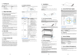
2.1 Hardware Introduction
The interfaces and indicators of this series switch are the same. Here takes 8-Port
Switch (720W) as example.
Front Panel

3
Side Panel
The interfaces and indicaotors of this series switch are of the same parameter as
following.
Led Indicators Instructions
Indicators
Status
Descriptions
PWR
Power Indicator
On
The power is on.
Off
The power is off.
SYS
System Working
Indicator
Blink
System is working normally.
On/Off
System failure
ALM
Relay Alarm Indicator
On
The device alarms.
Off
The device is working normally.
X1~2
X1/X2 SFP Port
indicator
On
X1/X2 SFP port is linking normally.
Blink
X1/X2 SFP port is transmitting or
receiving data.
Off
X1/X2 SFP port is linking down.
Port Link Indicator
On
The port is linking normally.
Blink
The port is transmitting or receiving
data.
Off
The port links down.
Port PoE Indicator
On
The port is supplying PoE normally.
Off
The port stops supplying PoE.

4
Power Supply Port
The input power supply port of the device adopts removable 6-position terminal block.
The electrical performance are as follows.
Specifications
Descriptions
Wire range
28~12 AWG (2.5mm²)
Torque
4.08kgf.cm (3.5Lb-In.)
Wire strip length
7~8mm
Dielectric Strength
AC 2500V/1 minute
Rating
300V/15A
Relay Interface
The switch supports relay alarm function.
The input port of the relay interface adopts removable 2-position terminal block. The
electrical performance are as follows.
Specifications
Descriptions
Wire range
28~12 AWG (2.5mm²)
Torque
4.08kgf.cm (3.5Lb-In.)
Wire strip length
7~8mm
Dielectric Strength
AC 2500V/1 minute
Rating
300V/15A
The “Relay Interface” could be connected with warner device, such as a buzzer.
In the following cases, the switch will alarm and the ALM Indicator will turn on.
Alarm cases
Descriptions
Indicators
Port Network
Disconnected
The linking port is disconnected.
In this case, the port link indicator is off, please
check the network cable.
Port PoE Off
The port stops supplying PoE.
In this case, the port PoE indicator is off, please
check the PoE function.
Console Port
The device contains a serial RS-232 interface as the console port for local management
interface. For the console port, a standard RJ-45 connector is used. Use a RS-232
calbe (Sub-D9 to RJ-45) to connect the console port with the COM port of a PC.

5
Default configuration:
Data
Default value
Transfer rate
115200 bit/s
Flow control mode
Not support
Test mode
Not support
Stop bits
1
Data bits
8
Init Button
The init button has two operating modes.
By short pressing the button, the switch will be reset and the configuration is as
previous setting saved.
By pressing the button over 5s, the switch will be restored to the original factory
default setting.

6
Installations
3.1 Safety Precaution
To minimize the technically residual risk, it is imperative to obey the following rules.
Read all the instructions before operation.
The Caution, Warning and Danger items in this document do not cover all the safety
precautions that must be followed. They are only supplementary information.
When operating the device, obey the local safety regulations. The safety precautions
provided in the documents are supplementary and shall be in compliance with the local
safety regulations.
Operator
Only qualified and skilled personnel can install, configure, and disassemble the
device.
Only the personnel authorized can operate the device.
Any replacement or change to the device or parts of the device (including the
software) must be done by qualified or authorized personnel.
Any fault or error that might cause safety problems must be reported immediately
to the person in charge.
Ground
For better protection performance, it is recommended as follows.
Do not damage the ground conductor or operate the device in the absence of well
installed ground conductor. Conduct the appropriate electrical inspection.
When operating the unit, always make the ground connection first and disconnect
it at the end.
Human Safety
Do not operate the device or cables at lightning strikes.
If the device is designed with optical port, do not look directly into the optical port to
prevent the laser radiation from injuring your eyes.
Do not wear jewelry or watches when you operate the device.
Equipment Safety
Before operation, the device must be fixed securely on the floor or to other reliable
objects, such as the desktop, the walls or the mounting racks.
Do not block the ventilation while the device is running. Keep a minimum distance
of 5 cm from the ventilation to the walls or the other objects that block the ventilation.
Tighten the thumbscrews by using a tool after both initial installation and
subsequent access to the panel.

7
Inflammable Environment
DANGER
Do not place the device in the environment that has inflammable and explosive air
or fog. Do not perform any operation in this environment.
Operating the electrical device in inflammable environment can be fatal.
Moisture Proof
WARNING
Water or moisture in the equipment will damage the circuit of the equipment.
The installation environment of the equipment must be strictly prohibited from water
seepage, dripping, and condensation, otherwise it is necessary to install
dehumidification equipment (such as air conditioners with dehumidification function,
special dehumidifiers), etc.
It is forbidden to operate the equipment under or near the water source, such as
the sink, laundry room or other high humidity areas.
It is forbidden to touch the device with wet hands.
Dust Proof
Install the equipment far away from sand and dust sources, such as coal mines,
rural roads, and farmland, etc.
It is forbidden to operate the device in a dense dust environment.
Ventilation
WARNING
Operating equipment will release heat. Please ensure that the environment where
the equipment is installed is well ventilated to ensure the equipment operating
normally.
It is strictly forbidden to install the equipment near heat sources, such as stoves,
heaters, etc.
Ensure that the equipment installation environment has good air flow.
If the equipment is designed with heat dissipation holes, it is strictly prohibited to
block the heat dissipation hole of the device.

8
3.2 Installation Steps
This series switch supports 3 installation ways:
DIN rail installation
Wall mounted installation
Desktop installation
The dimensions and installation of this series switch are the same.
Following with the dimensions of the switch and its insatallation accessories.
Dimensions (mm)

9
3.2.1 DIN-rail Installation
Please follow the steps below.
Step 1 Fix the DIN-rail hanger to the switch.
Accessories
1*
2*
Step 2 Install the switch to the DIN rail.
Accessories
N/A

10
3.2.2 Wall mounted Installation
Please follow the steps as below.
Step 1 Fix the two hangers to the switch.
Accessories
2*
4*
Step 2: Install the switch on desktop or drill 4 holes on the
wall where the switch is going to be installed. Please refer
to the dimensions as below.
Accessories
4*
3.2.3 Desktop Installation
The switch supports desktop installation. Users can put this product on clean, stable,
grounded workbench. The installation steps are as below:
Carefully put the device upside down, clean the grooves on the chassis backplane
with soft cloth to make sure there is no oil or dust in it.
Remove the stickers on the foot pad, paste the foot pad in backplane groove.
Carefully put the device upright on the workbench.

11
3.2.4 DC Power Cable Connection
There are two ways for the switch to connect the DC power.
Through terminal block.
Connect with power adapter of DIN rail power supply.
The installation processes are as follows.
Before installation, ensure that the device is disconnected from the power supply.
Connect one end of the protective grounding cable to the grounding screw on the
side panel of the device, and the other end is well grounded nearby.
Connect the positive and negative wires of DC power separately to the “+” and “-”
power terminal on the switch as following figure, tightening with screw driver.
Turn on the DC power, and check if the PWR led turns on, which means the power
supply is connected correctly.
Installation steps are finished.
CAUTION
For better transmission performance, it is recommended to use Cat6A or better
cables to connect the switch and powered device.
For better protection performance, it is recommended always to make the ground
connection first and disconnect it at the end when operating the unit.
Power on the system only after confirming that the wiring is correct, to avoid
damage to the equipment.
Read the user manual carefully before operating or maintaining the repeater to
avoid misoperation.

12
Specifications
Items
8-Port Switch (480W)
8-Port Switch (720W)
Physical Port
Downlink Ports
8*10/100/1000Base-T PoE++ RJ-45(Auto-MDI/MDI-X)
Uplink Ports
2*1000 Base-X SFP(Mini-GBIC)
Console Port
1*RS-232 console port (115200,8,N,1)
Alarm Output
1 channel relay alarm output, 1A@DC 12V
2 cores, 5.08mm terminal
PoE
PoE Standard
802.3af/at/bt (PSE)
PoE Power Supply Type
End-span
PoE Line Pair
3/6/4/5(+), 1/2/7/8(-)
3/6/4/5(+), 1/2/7/8(-)
PoE Power Output
52~57V DC
PoE Budget
90W max for each port
(full load with 52V DC
input voltage), 480W max
for whole switch
90W max for each port
(full load with 52V DC
input voltage), 720W max
for whole switch
Switching Property
Standard and Protocols
IEEE 802.3, IEEE 802.3u, IEEE 802.3ab, IEEE
802.3z, IEEE 802.3x, IEEE 802.1D
Forwarding Modes
Store and Forward
Packet Buffer
4Mbits
MAC Table
8k
Switching Capacity
20Gbps / non-blocking
Packet Forwarding Rate
14.9Mpps
Jumbo Frame
16kB
Power Supply
Input Voltage
DC 48V~57V
Power Consumption
20W (Not included PoE)
Reliability
Surge Immunity
6kV, Standard: IEC6000-4-5
ESD Immunity
8kV Contact Discharge,8kV Air Discharge
Standard: IEC61000-4-2
MTBF
285130h
MTBF Standards
Telcordia SR-332, 25

13
Operating Temperature
-10 ~50
-40 ~55 (720W)
-40 ~75 (420W)
Storage Temperature
-40~85
Operating Humidity
5%~95% (Non-condensation)
Physical Parameters
LED Indicator
1* Power indicator
1* System status indicator
1* Alarm indicator
2* SFP port indicators
8* Port Link/ACT indicators
8* PoE indicators
Init Button
Short press to restart
Long press 5s to initialize the system
Dimension(W*D*H)
163.2mm*110mm*65.8mm
Net Weight
1210g 20g
1560g20g
Material
Metal shell
Installation
DIN-rail/wall mounted/desktop
Certifications
Certifications
CE, FCC


/