1 Packing List
Please check the following items after unpacking, if any missing, please
contact your local dealer.
2 Safety Information
Before performing an operation, read the following operation instructions
and precautions to be taken, and follow them to prevent accidents.
2.1 General Requirements
Only qualified and skilled personnel must install, configure, and
unmount the device. The device must not be disassembled.
When operating the device, obey the local safety regulations. The
safety precautions provided in the document are supplementary and
shall be in compliance with the local safety regulations.
When operating the device, in addition to the precautions (please see
the notes below), follow the specific safety instructions.
The installation and maintenance personnel need to understand the
basic safety precautions to be taken.
Do not block the ventilation while the device is running. Keep a
minimum distance of 5 cm from the ventilation to the walls or the other
objects that block the ventilation.
Do not operate the device in an area that exceeds the maximum
recommended ambient temperature of 75°C.
Do not place the device in the environment that has inflammable and
explosive air or fog. Do not perform any operation in this environment.
2.2 Electric Safety
Connect the unit only to DC power source that complies with the safety
extra-low voltage (SELV) requirements in IEC62368-1 based safety
standards.
Before touching the device or hand-operating parts, wear a grounded
electrostatic discharge (ESD) wrist strap. It can prevent the sensitive
components from damage by the static electricity in the human body.
2.3 Optical Safety
When handling optical fibers, do not stand close to, or look at the
optical fiber outlet directly with unaided eyes.
Cutting and splicing fibers must be performed by the trained personnel
only.
Before cutting or splicing a fiber, ensure the fiber is disconnected from
the optical source. After disconnecting the fiber, use protecting caps to
protect all the optical connectors.
3 Product Introduction
3.1 Overview
The switch is Industrial 4-Port Gigabit PoE+ 2-Port SFP L2 Managed
Ethernet Switch.
This switch provides 4 Gigabit Ethernet RJ-45 ports and 2 Gigabit SFP
uplink ports. It meets IEEE 802.3af/at standard. All RJ-45 ports support
Power-over-Ethernet (PoE+) and deliver up to 30W power per port.
The switch has extensive L2 management functions, such as 802.1Q
VLAN, 802.1P QoS, STP/RSTP, Link aggregation, DHCP and PoE control.
It can be easily managed via a WEB GUI (http/https), CLI
(telnet/ssh/console) or SNMP.
3.2 Hardware Introduction
The system is working normally.
Console Port
The device contains a RJ-45 interface as the console port for local
management interface. For the console port, a standard RJ-45 connector
is used. Use a RS-232 cable (Sub-D9 to RJ-45) to connect the console
port with the COM port of a PC.
See the default configuration in chapter “6 Factory Settings”.
Init Button
The init button has two operating modes.
By short pressing the button, the switch will be reset and the
configuration is as previous setting saved.
By pressing the button over 5s, the switch will be restored to the
original factory default setting.
4 Installations
The switch supports DIN-rail installation.
The DIN-rail hanger is fixed on the switch at the factory. Please Install the
switch to the DIN rail directly.
Install the switch to the DIN rail.
5 Connect the Power Supply
Note:
The equipment is intended to be grounded to comply with emission and
immunity requirements. Ensure that the switch functional ground screw is
connected to earth ground during normal use.
Use one end of GND cable to connect the M3 grounding connector of the
switch, the other end to a ground point. The GND of the switch is shorted
to the copper protection ground bar provided by the user. The GND cable
used is recommended to be plastic insulating one with copper core, with
cross-sectional area greater than 1.5mm².
Ground the switch housing
The switch is powered by a 48~57V DC power connection. It supports
redundant power supply.
It is possible to connect a second power source using the same voltage
with the redundant power supply port. If one source fails, the alternative
source takes over the power supply without interruption.
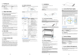
5.1 48~57V DC Supply
The power supply connectors are equipped with 6-pin plug connectors (2
NC pins in the middle of the connector). Please observe the polarity.
Use DC power cable to connect positive/negative wires of DC power
separately to the “+” and “-” power terminals, using a screw driver to
screwing stably. Connect the main supply to the building’s power supply
network.
Connect DC power to the DC Power Connector
Please observe the following specifications:
5.2 Starting Up
After connection to the power supply, the switch starts automatically and is
ready for operation after approx. 90 s.
LED indicators “P1” or “P2” turns green.
Note:
To switch off the device, always disconnect both the main and redundant power
supply.
Note:
Please note that the factory settings may change with future firmware versions.
For this reason we recommend that you check the release notes for information
about any changes to the factory settings before carrying out a firmware
update.
The switch starts with its factory settings:
Console Port
(Sub-D9 to RJ-45)
Enabled
Baud rate: 115200 bit/s
Flow control: No flow control
Parity: No parity check
Stop bits: 1
Data bits: 8
User: admin
Password: admin
Access privilege: 15 (Full access rights, This
user can adjust all settings of the switch.)
Default static IP address
Ports 1~4
1000M bit/s operation enabled in VLAN 1
Ports 5~6
SFP inserted: 1000Base-X operation
7 Access Network Management
After starting up successfully, connect the switch to your local network
segment using a suitable cable to access the switch network management
system. For details, please refer to one of the following documents:
Web Configuration Guide
Describes Web network management system configuration instructions.
CLI Configuration Guide
Describes CLI-based configuration instructions.
8 Specifications
4*10/100/1000Base-T PoE+ RJ-45
Short press to restart the switch
Long press >5s to initialize the system
2*power indicators
1*system indicator