Page is loading ...

IMPORTANT NOTE:
Please read this manual carefully before installing or operating your air conditioning unit.
That’s better. That’s Actron.
Model Numbers
LM7-2W (White)
LM7-2G (Grey)
LM24-2W (White)
LM24-2G (Grey)
WALL CONTROLLER
Operation Manual

Operation Manual LM7/24-2 Wall Controller
Operation Manual LM7-2 / LM24-2 Wall Controller
Document No. 0525-079 Ver. 1 190821
Page 2
Table of Contents
01. General Informations .......................................................................................3
02. Waste Electrical and Electronic Equipment Disposal Guidelines ...................... 4
03. Maintenance ................................................................................................... 4
04. Safety Precautions ........................................................................................... 4
05. Operational Precautions ...................................................................................5
06. System Information .......................................................................................... 5
07. Features ...........................................................................................................6
08. Basic operation ................................................................................................7
09. Program Menu (LM7-2) ................................................................................... 15
10. Zone Controller Functions .............................................................................. 18
11. Dual Wall Controller Operation ...................................................................... 19
12. Setting The Upper And Lower Temperature Limits .........................................20
13. Operating Tips ...............................................................................................21
14. Cleaning Maintenance .................................................................................... 22
15. Troubleshooting ............................................................................................ 23
16. Re-Setting The Wall Control ...........................................................................24
17. Near Field Communication (NFC) Tag .............................................................24

Page 3
Operation Manual LM7/24-2 Wall Controller
Operation Manual LM7-2 / LM24-2 Wall Controller
Document No. 0525-079 Ver. 1 190821
01. General Informations
CONGRATULATIONS! The LM7-2(W/G) / LM24-2(W/G) Control Interface is manufactured from the highest quality
materials and designed to ensure years of satisfactory operation.
IN THIS MANUAL, You will find instructions on how to program and utilise the many advanced features this control
interface has to offer. Please take time to familiarise yourself with all these features, apply their functions to suit your
optimum comfort requirement and achieve energy cost savings at the same time. Thoroughly read this manual in order
to ensure correct utilisation of your ActronAir air conditioner.
IMPORTANT NOTICE, ActronAir base the development of its air conditioning products on more than 30 years of
experience in HVAC, sound and continuous investments in technological innovations and product improvements,
advancement in manufacturing processes and quality control through 100% functional product testing. However,
ActronAir cannot guarantee that all the aspects of the product and the software included with the product respond to
the requirements of final application, despite the product being developed according to state of the art technology. The
customer, both end user/specifier and installer, assume all liability and risks relating to the configuration of the product in
order to reach the expected results in relation to the specific design and system installation. ActronAir, based on specific
agreements, may be consulted for the positive commissioning, installation and application of the unit, however in no
case does ActronAir accept liability for the correct operation of the final equipment / system.
Your ActronAir air conditioning unit is one of the most advanced and innovative products in the market. Its operation
is specified in the technical documentation supplied with the product or which can be downloaded from our website:
www.actronair.com.au. Your air conditioner requires set-up/configuration/programming in order to be able to operate
in the best possible way to suit your requirement. Failure to complete such operations, may result in malfunction and/or
damage to the unit, for which ActronAir accepts no liability.
Installation, commissioning and other technical services must only be carried out by a qualified technician. Ensure that
the unit installation complies with all relevant council regulations and building code standards. All electrical wiring must
be in accordance with current electrical authority regulations and all wiring connections to be as per electrical diagram
provided. Always use appropriate PPE for your safety and protection. Make sure that any safety guards and covers
are always firmly secured and not damaged. WH&S rules and regulations must be observed at all times and will take
precedence during installation process and operation of the unit.
In addition, the following instructions must be observed:
•Prevent the electrical components and electronic circuits from getting wet.
•Do not install the controlling devices in hot environments as extreme temperatures may damage the electronic
equipment.
•Do not attempt to open the controller and other electronic devices in any way other than described in this manual.
•Do not drop, shake or hit the devices, which can cause irreparable damage to its internal circuits and mechanisms.
•Do not use corrosive chemicals, solvents or other aggressive detergents to clean the unit and the control interface.
•Do not use the unit for applications other than those specified in the technical manual.
•Do not install the unit in environment with highly flammable, combustible and/or explosive articles and materials.
•This control interface must be installed in a location that complies with the temperature and humidity limits specified
in this manual.
ActronAir is constantly seeking ways to improve the design of its products, therefore specifications are subject to change
without prior notice. Please check with ActronAir Service Department on toll free number: 1800 119 229.
SPECIFICATIONS:
•Voltage: 12VDC
•Data: RS485 4 Core (2 Pair) Twisted Pair 7/0.20 (AWG24) Shielded Data Cable
•Storage conditions: -20 to 70oC, < 90% RH non-condensing
•Operating conditions: -10 to 60oC, < 90% RH non-condensing

Operation Manual LM7/24-2 Wall Controller
Operation Manual LM7-2 / LM24-2 Wall Controller
Document No. 0525-079 Ver. 1 190821
Page 4
02. Waste Electrical and Electronic Equipment Disposal Guidelines
1. Do not dispose off the waste electrical and electronic equipment with local council waste. These must be
disposed off through the council designated hazardous waste collection centre.
2. The equipment may contain hazardous substances, improper or incorrect disposal may have a negative effect
on human health and on the environment.
03. Maintenance
1. Keep the control interface clean with the use of a soft dry cloth only. If a cleaning solution is needed, use a very mild
soap solution to dampen the cloth. Do not spray or squirt any liquid onto your control interface.
2. Do not use solvent base cleaner, which can cause damage to the control interface.
3. When cleaning, be careful not to accidentally press any Buttons, TURN-OFF the unit to ensure that no adverse unit
operation is initiated by accidentally pressing any Buttons.
4. Be careful not to press hard into the display screen, as it may get damaged.
5. Ensure that the temperature sensor is always clean and free of dust or dirt build-up to maintain sensor accuracy.
6. Do not pull apart or attempt to service the control interface, should you need service to the device, contact
ActronAir Service Department on 1800 119 229.
04. Safety Precautions
1. Read all instructions in this manual before operating the air conditioning unit. Failure to do so may result in damage
to the unit and void your warranty.
2. Turn-Off the power supply to the unit and follow sound Lock Out and Tag Out procedures to ensure that power
supply is not re-energised accidentally.
3. Beware of EC Motors with high power capacitors and which can have dangerous voltages at terminals for up to 5
min. after main power has been isolated. Wait at least 5 minutes after power isolation and test for high voltage before
performing service work.
4. This control interface has power supplied from the indoor board controller via screwed terminals and 4 Core Twisted
Pair Data cable. Ensure that this unit is not installed on voltages other than specified.
5. Installation and servicing must be carried out by a qualified technician.
6. Ensure that the unit installation complies with relevant council regulations and building code standards. All electrical
wiring must be in accordance with current electrical authority regulations and all wiring should follow the electrical
diagrams provided.
7. WH&S rules and regulations must be observed and will take precedence during installation process.
8. Only use this control interface with an ActronAir air conditioner as described in this operating manual.

Page 5
Operation Manual LM7/24-2 Wall Controller
Operation Manual LM7-2 / LM24-2 Wall Controller
Document No. 0525-079 Ver. 1 190821
05. Operational Precautions
ACCESS PANELS AND GUARDS: NEVER remove any access panels or guards as this could cause injury from electric shock
and burns from extremely hot components. Never allow any bodily parts such as fingers or objects to protrude through
the fan guards or any other opening as they could cause personal injury and damage the air conditioner.
SUPERVISION OF CHILDREN AND INFIRM PERSONS: This appliance is not intended for use by young children or infirm
persons unless they have been adequately supervised by a responsible person to ensure that they can use the appliance
safely. Young children should be supervised to ensure that they do not play with the appliance.
RETURN AIR FILTER: The air conditioner must never be operated without a return air filter as this will cause a build
up of dust and other contaminants on the indoor coil. This is very difficult to clean and causes the system to operate
inefficiently or even fail.
CRANKCASE HEATER PRECAUTION: The main power ( Outside switch board ) to the system must be kept ON at all times
to prevent damage to the outdoor compressor unit. Should the main power be disconnected or interrupted for 6 hours
or longer, then no attempt should be made to start the system for 2 hours after the power has been restored to outdoor
unit. This allows the compressor to warm up, and remove any liquid refrigerant that may cause damage.
06. System Information
Air Conditioner
Model No.
Serial No.
The air conditioner model and serial number is situated on the access panel of
the outdoor unit bottom left corner.
Wall Controller
Model No.
The wall controller model number is situated in front of the wall controller
Installer
Company Name
Phone Number
Technicians Name

Operation Manual LM7/24-2 Wall Controller
Operation Manual LM7-2 / LM24-2 Wall Controller
Document No. 0525-079 Ver. 1 190821
Page 6
07. Features
1
Auto-Restart After Power Failure
Should a power failure occur whilst the air conditioner is running, the wall
controller will restart the air conditioner in the same mode when the power is
restored, if this option is selected.
2
Dual Wall Control Operation (Optional)
Up to two wall controllers can be installed on one system. This is particularly
useful on two storey houses , where you can have one control upstairs and one
control downstairs or having the second wall controller in the master bedroom
for improved temperature control. See Dual Wall control Operation for more
info on Page 20.
3
Room Temperature Display with One Touch
Press the or Buttons and the set temperature display will change to
show the room temperature for 3 seconds.
Note: When zones are fitted, the temperature displayed will depend on which sensor has
been selected by the wall controller ( See Zone Controller Functions, Page 19 ).
4
Integrated Zoning
The integrated zoning system has a unique feature where it can select which
remote temperature sensor to use depending on which zones are selected. One
example is on a two-storey house and you only have the downstairs zone on,
the zone control will select the downstairs sensor to control the temperature,
thus ensuring perfect comfort in the area occupied.
5
Auto Defrost Function (Heating Mode)
At certain outdoor conditions (low temperature) there may be a build up of
frost on the outdoor heat exchanger. This gradual build up of frost reduces the
performance of the air conditioner. The microprocessor detects this frost build
up and will automatically activate the defrost mode.
The defrost mode is displayed on the wall controller by flashing the HEAT
indicator every 10 seconds.
6
Hot Start Function (Heating Mode)
When the air conditioner starts in heating mode, the indoor fan is delayed for a
short period of time, this allows the heat exchanger to warm up before the air
flow starts, thus minimising cold drafts. The hot start feature also activates itself
when the system finishes defrosting.
7
Filter Clean Light
The system monitors the accumulated run time of the air conditioner and after
a preset number of hours have expired, the FILTER indicator will flash, indicating
it’s time to check if filter requires cleaning.
8
Self Diagnosis
In the unlikely event that a fault develops with the air conditioner the
microprocessor will detect a fault and display the relevant fault code on the wall
controller. See Troubleshooting on Page 23.
NOTE
Some applications may require cleaning of the filter at more regular intervals.

Page 7
Operation Manual LM7/24-2 Wall Controller
Operation Manual LM7-2 / LM24-2 Wall Controller
Document No. 0525-079 Ver. 1 190821
08. Basic operation
08.01. Wall Controller Functions
LM7-2 and LM24-2 have the same Buttons and functions, except for items 2, 6 and 20 which are not available
to LM24-2.
LM7-2
1
3
15
2
4
5
6
16
17
18
19
20
LM24-2
21
11
7 8 12 13
9 14
10 22
1LCD Display
Displays the setting and operation conditions
(See next page for details).
2Program Button (Not used on LM24-2)
For setting the clock and for entering the
7-Day time clock menu.
3Fan Control Button
Changes fan speed (high, medium and low).
Selects continuous and non continuous fan
operation. Also selects FAN only mode.
4Temperature-Up Setting Button
Increases room temperature setting.
5Temperature-Down Setting Button
Decreases room temperature setting.
6Exit Button (Not used on LM24-2)
Quick exit from time clock programming
menu.
7Zone 1 Button with On/Off Indicator
8Zone 2 Button with On/Off Indicator
9Zone 3 Button with On/Off Indicator
10 Zone 4 Button with On/Off Indicator
11 Zone 5 Button with On/Off Indicator
12 Zone 6 Button with On/Off Indicator
13 Zone 7 Button with On/Off Indicator
14 Zone 8 Button with On/Off Indicator
15 On/Off Button
16 Timer Operation Button
Activates timer function.
17 Operation Mode Button
Selects cooling, heating and Auto mode.
18 Select/Clock-Up Setting and Room Temp
Display Button
19 Select/Clock-Down Setting and Room
Temp Display Button
20 Repeat / Backlight Button (LM7-2 only)
• Repeats the previous day settings to the
current day.
• Adjust and Turn On/Off Backlight.
21 Display / Backlight Button (LM24-2 only)
Adjust and Turn On/Off Backlight.
22 NFC Tag

Operation Manual LM7/24-2 Wall Controller
Operation Manual LM7-2 / LM24-2 Wall Controller
Document No. 0525-079 Ver. 1 190821
Page 8
41
39
40
32
44
24 26 27
22 25
36 38
37
23
33 34
42
35
43
LM7-2 Display
30
31
29
28
41
39
40
32
26 27
36 38
37
23
33 34
42
35
43
LM24-2 Display
31
28
NOTE
Wall Controllers LM7-2 and LM24-2 are available in 2 colours.
• LM7-2W (White) and LM7-2G (Grey)
• LM24-2G (White) and LM24-2G (Grey)

Page 9
Operation Manual LM7/24-2 Wall Controller
Operation Manual LM7-2 / LM24-2 Wall Controller
Document No. 0525-079 Ver. 1 190821
22 Day Indicator (LM7-2 only)
Display the day of the week when the time
is shown and which day is selected for
programming.
23 Time Indicator
Indicates timer is in operation.
24 Time Clock Indicator (LM7-2 only)
25 Event Indicator
Indicates which event of the day Time
clock is being set.
26 On Indicator
27 Off Indicator
28 Timer CLock and Room/Setpoint
Temperature Indicator (LM7-2 only)
Displays the setpoint and current room
temperatures, current time, count down
timer times and event times.
28 Timer and Room/Setpoint
Temperature Indicator (LM24-2 only)
Displays the setpoint and current room
temperatures and Filter countdown time.
29 AM Indicator (LM7-2 only)
30 PM Indicator (LM7-2 only)
31 Inside Room Temperature Indicator
Flashes to indicate current room
temperature reading.
32 Low Speed Fan Indicator
33 Medium Speed Fan Indicator
34 High Speed Fan Indicator
35 Set Indicator
Illuminates during time and time clock
setting adjustments.
36 Degree Centigrade Indicator
Flashes to indicate current room
temperature reading.
37 Run Indicator
Indicates the outdoor unit is in operation,
flashes if on delay.
38 Auto Indicator
Indicates the system will automatically
select heating or cooling operation.
39 Heating Operation Indicator
40 Cooling Operation Indicator
41 Filter Indicator
42 Continuous Indicator
Illuminates when fan is set to continuous
mode of operation.
43 Lock Symbol
Shows during backlight adjustments and
when Turning On/Off backlight.
44 1 and 2 Indicator (LM7-2 only)
Illuminates together with Event to show the
programming event.

Operation Manual LM7/24-2 Wall Controller
Operation Manual LM7-2 / LM24-2 Wall Controller
Document No. 0525-079 Ver. 1 190821
Page 10
08.02. LCD Backlight Functions
LM7-2 / LM24-2
08.02.01. LCD Backlight Level Adjustments
1. Press and hold the REPEAT (LM7-2) or the DISPLAY (LM24-2) Button.
2. Press the or Buttons to adjust the backlight level as follow:
• To brighten the backlight, press the Button.
• To dim the backlight, press the Button.
3. Release the buttons at the desired level of LCD brightness. The symbol will appear for 1 second showing
that the backlight level is set.
08.02.02. Turn ON/OFF LCD Backlight
To turn ON LCD backlight
1. Press and hold the REPEAT (LM7-2) or the DISPLAY (LM24-2) Button for 4 seconds.
2. When the symbol appears, release the REPEAT (LM7-2) or the DISPLAY (LM24-2) and the backlight will
remain Illuminated.
To turn OFF LCD Backlight
1. Press and hold REPEAT (LM7-2) or DISPLAY (LM24-2) Button for 4 seconds.
2. When the symbol appears, release the REPEAT (LM7-2) or DISPLAY (LM24-2) and the backlight will turn
Off after 6 seconds.
08.02.03. Turn On the ON/OFF Button Light
NOTE
The Wall Controller must be turned ON before operating this procedure. By default, the Button backlight is
ON.
1. Press and hold the REPEAT (LM7-2) or the DISPLAY (LM24-2) Button.
2. Press and release the Button , along with the REPEAT (LM7-2) or the DISPLAY (LM24-2) Button.
3. The symbol will appear and the Button light will remain lit.
08.02.04. Turn Off the ON/OFF Button Light
1. Press and hold the REPEAT (LM7-2) or DISPLAY (LM24-2) Button.
2. Press and release the Button , along with the REPEAT (LM7-2) or the DISPLAY (LM24-2) Button.
3. The symbol will appear and the Button light will turn Off after 6 seconds.

Page 11
Operation Manual LM7/24-2 Wall Controller
Operation Manual LM7-2 / LM24-2 Wall Controller
Document No. 0525-079 Ver. 1 190821
08.03. Cooling Operation (LM7-2)
1. Press the Button.
2. Press the Button until COOL appears on the display.
3. Set the desired temperature by pressing either the or Buttons.
• Maximum temperature setting 30.
• Minimum temperature setting 16.
• For a WARMER room temperature, press the Button.
• For a COOLER room temperature, press the Button.
4. Adjust the desired fan speed by pressing the Button. When your air conditioner is turned On the indoor
fan can run continuously and is indicated by the CONT indicator. This is generally preferred during the cooling
mode to ensure maximum air circulation. However, during the heating mode this can create the effect of cool
drafts. It then would be preferable to have the indoor fan, cycle On and Off automatically with the Outdoor Unit.
This is selected by pressing the Button until the CONT indicator is Off.
5. Press the Button again. The system will retain your last setting until next operation.
08.04. Heating Operation (LM7-2)
1. Press the Button.
2. Press the Button until HEAT appears on the display.
3. Set the desired temperature by pressing either the or Buttons.
• Maximum temperature setting 30.
• Minimum temperature setting 16.
• For a WARMER room temperature, press the Button.
• For a COOLER room temperature, press the Button.
4. Adjust the desired fan speed by pressing the Button. When your air conditioner is turned On the indoor
fan can run continuously and is indicated by the CONT indicator. This is generally preferred during the cooling
mode to ensure maximum air circulation. However, during the heating mode this can create the effect of cool
drafts. It then would be preferable to have the indoor fan, cycle On and Off automatically with the Outdoor Unit.
This is selected by pressing the Button until the CONT indicator is Off.
5. Press the Button again. The system will retain your last setting until next operation.

Operation Manual LM7/24-2 Wall Controller
Operation Manual LM7-2 / LM24-2 Wall Controller
Document No. 0525-079 Ver. 1 190821
Page 12
08.05. Auto Operation (LM7-2)
NOTE
Automatically changes between heating and cooling mode.
1. Press the Button.
2. Press the Button until AUTO appears on the display.
3. Set the desired temperature by pressing either the or Buttons.
• Maximum temperature setting 30.
• Minimum temperature setting 16.
• For a WARMER room temperature, press the Button.
• For a COOLER room temperature, press the Button.
4. Adjust the desired fan speed by pressing the Button. When your air conditioner is turned On the indoor
fan can run continuously and is indicated by the CONT indicator. This is generally preferred during the cooling
mode to ensure maximum air circulation. However, during the heating mode this can create the effect of cool
drafts. It then would be preferable to have the indoor fan, cycle On and Off automatically with the Outdoor Unit.
This is selected by pressing the Button until the CONT indicator is Off.
5. Press the Button again. The system will retain your last setting until next operation.
08.06. Fan only operation (LM7-2)
NOTE
The system’s status must be of to set Fan mode.
1. Press the Button.
2. Adjust the FAN speed by pressing the Button .
3. To turn Off the fan operation, press the Button again.

Page 13
Operation Manual LM7/24-2 Wall Controller
Operation Manual LM7-2 / LM24-2 Wall Controller
Document No. 0525-079 Ver. 1 190821
08.07. ESP Fan Feature
Available for ESP Plus and ESP Ultima Models
CIRCULATION OPERATION
Fan Speed Cycle:
HIGH = High air circulation.
MED = Normal air circulation.
LOW = Low air circulation.
ESP = Variable air circulation, varying fan speed will be determined by the controller automatically. This will
depend on number of outlets or zones open in an installation.
Wall Controller Display
SPEED SEGMENT INDICATOR LCD DISPLAY
HIGH MED LOW
HIGH ON SET TEMP
MED ON SET TEMP
LOW ON SET TEMP
ESP ON ON ON ESP THEN SET TEMP
CIRCULATION OPERATION
Fan Speed Cycle:
HIGH = High air circulation.
MED = Normal air circulation.
LOW = Low air circulation.
CONT HIGH = High air circulation, continuous run.
CONT MED = Normal air circulation, continuous run.
CONT LOW = Low air circulation, continuous run.
ESP = Variable air circulation, varying fan speed will be determined by the controller automatically. This will
depend on number of outlets or zones open in an installation.
CONT ESP = Continuous variable air circulation, varying fan speed will be determined by the controller
automatically. This will depend on number of outlets or zones open in an installation.
LOW
CONT ESP
ESP
CONT
HIGH
CONT
MED
CONT
LOW
HIGH MED
FAN CYCLE
Wall Controller Display
SPEED SEGMENT INDICATOR LCD DISPLAY
HIGH MED LOW CONT
HIGH ON SET TEMP
MED ON SET TEMP
LOW ON SET TEMP
ESP ON ON ON ESP THEN SET TEMP
CONT HIGH ON ON SET TEMP
CONT MED ON ON SET TEMP
CONT LOW ON ON SET TEMP
CONT ESP ON ON ON ON ESP THEN SET TEMP

Operation Manual LM7/24-2 Wall Controller
Operation Manual LM7-2 / LM24-2 Wall Controller
Document No. 0525-079 Ver. 1 190821
Page 14
08.08. Timer Operation (LM7-2)
08.08.01. OFF Timer Function
NOTE
The system’s status must be On to set an OFF timer.
1. Press the TIMER Button to enter the timer menu.
2. Press the or Buttons to select the desired time for the system to remain operating before
turning Off. The maximum adjustable timer hours are 24 with 0.5 hour (30 minute) adjustable
increments.
3. If a timer is active, TIMER indicator will be displayed. To cancel the OFF Timer, press the Button and
the TIMER indicator will disappear.
4. To change the Hour Set, follow the steps 1 and 2.
08.08.02. On Timer Function (LM7-2)
1. Press the TIMER Button to enter the timer menu.
NOTE
The system’s status must be Off to set an On timer.

Page 15
Operation Manual LM7/24-2 Wall Controller
Operation Manual LM7-2 / LM24-2 Wall Controller
Document No. 0525-079 Ver. 1 190821
2. Press the or Buttons to select the desired time for the system to remain operating before
turning On. The maximum adjustable timer hours are 24 with 0.5 hour (30 minute) adjustable
increments.
3. To cancel the TIMER, press the Button.
4. To change the Hour Set, follow the steps 1 and 2.
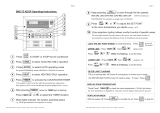
09. Program Menu (LM7-2)
09.01. 7-Day Programmable Function
09.02. Time Clock Operation
NOTE
• The 7-Day Time clock feature of the LM7-2 controller allows you to set the air conditioner to turn ON and OFF
at different times for each day of the week.
• Each day can have 2-Programmed Events.
• Each event has an On and Off time.

Operation Manual LM7/24-2 Wall Controller
Operation Manual LM7-2 / LM24-2 Wall Controller
Document No. 0525-079 Ver. 1 190821
Page 16
09.02.01. Example of Timeclock Operation
MON TUE WED THU FRI SAT SUN
EVENT 1
ON
TIME 6:00am 6:00am 6:00am 6:00am 6:00am 7:00am 8:00am
OFF TIME 10:00am 10:00am 10:00am 10:00am 10:00am 9:00am 11:00am
EVENT 2
ON
TIME 4:00pm 4:00pm 4:00pm 4:00pm 1:00pm -:-- -:--
OFF TIME 10:00pm 10:00pm 10:00pm 10:00pm 11:00pm -:-- -:--
09.02.02. Cancelling an Individual Event
Go to On time for the event you wish to cancel and press the Button. -:-- will be displayed indicating
the event is cancelled.
09.03. Setting the Time and Day
1. Press the PROG Button 3 times and SET will be illuminated with TIME flashing.
2. Adjust the Hours by using the or Buttons.
3. Press the PROG Button.
4. Adjust the Minutes by using the or Buttons.
5. Press the PROG Button.
6. Adjust the Day by using the or Buttons.
Battery Back up
During a power failure, the clock remains the same and day via the backup battery inside the system.
09.04. Activating and Deactivating the 7-Day Time clock
Activating
1. Press the PROG Button twice.
2. Press the Button until ON is flashing.
3. Press the EXIT Button.
4. The TIME CLOCK indicator will be illuminated in the screen, indicating that the Time clock has been
activated.

Page 17
Operation Manual LM7/24-2 Wall Controller
Operation Manual LM7-2 / LM24-2 Wall Controller
Document No. 0525-079 Ver. 1 190821
De-activating
1. Press the PROG Button twice.
2. Press the Button until OFF is flashing.
3. Press the EXIT Button.
4. The TIME CLOCK indicator will be turned Off, indicating that the Time clock has been deactivated.
09.05. Programming the Events
In the following example, MONDAY, EVENT 1 and ON time will be activated.
1. Press the PROG Button repeatedly until EVENT 1 and MON is illuminating in the screen.
2. Press the or Buttons to adjust the time.
3. Press the PROG Button to move to Event 1 Off time and follow step 2.
4. Press the PROG Button to move to the next event.
The event time is entered once you press the PROG Button. If you press the EXIT Button before moving
to the next event, the time you have programmed will not be entered.
5. Repeat the above steps until you have programmed all the events you require.
Programming Past Midnight
• Event On times can be set up to 11:45 PM of the current day.
• Event Off times can be set to 9;00 AM the following morning.
NOTE
If you program Event 1 past midnight, Event 2 will be automatically cancelled.
09.06. Cancelling an Individual Event
1. Press the PROG Button repeatedly until ON time for the event you wish to cancel is displayed.
2. Press the Button to delete event
3. -:-- will be displayed indicating the event is cancelled.
4. Repeat above steps to cancel other days event.
5. See 7-Day time clock operation for programming sequence. Page 15

Operation Manual LM7/24-2 Wall Controller
Operation Manual LM7-2 / LM24-2 Wall Controller
Document No. 0525-079 Ver. 1 190821
Page 18
Re-activating an Individual Event
1. Repeat steps 1 and 2 as above.
2. Press the Button until the time re-appears.
09.07. Repeating a Day’s Events and Times
This feature allows you to automatically repeat the previous days, events, and times, into the succeeding days.
1. Proceed to the day you wish to copy the programmed events and times. See Programming the Events
from previous page.
2. Press the PROG Button until you reach the succeeding day’s, Event 1, On time is displayed. SET, EVENT 1,
TIME CLOCK and ON will be illuminated in the screen.
3. Press the REPEAT Button. You have now copied the previous day’s events into the current day displayed.
4. Repeat Steps 2 and 3 above for the remaining days where you wish to repeat the programmed events and
times.
10. Zone Controller Functions
Turning Zones ON and OFF
1. Press the Zone Button to turn zones On and Off.
2. Lights are illuminated when zone is turned On.
NOTE
• By default, the minimum of one zone must be left On. This is controlled automatically by the wall control and will not
allow you to turn off the last zone operating. However, it is possible to turn Off all zones in some models. Contact
your installer for more details.
• Switching the last zone off will cause the controller to divert to Zone 1 automatically.
Room Temperature Display
1. Press the or Buttons and the room temperature will be displayed for 3 seconds.
NOTE
• The room temperature displayed can be the temperature at the wall controls or remote wall sensors or a
combination of both, depending on which zones are turned on.

Page 19
Operation Manual LM7/24-2 Wall Controller
Operation Manual LM7-2 / LM24-2 Wall Controller
Document No. 0525-079 Ver. 1 190821
11. Dual Wall Controller Operation
MIMIC Control
WALL
CONTROL ONE
WALL
CONTROL TWO
•The air conditioner can be operated from either wall controller.
•Information displayed on the two wall controllers is identical.
Example 1
Using wall controller one, the cooling operation is started, both wall controllers will now show the system is in cooling
mode. If another person uses wall controller two to select heating operation, the system will now change to the heating
operation and both wall controllers will display the system is in heating operation.
Example 2
Using wall controller two, the circulation operation is selected, both wall controllers will now show the system in
circulation mode. If another person uses wall controller two to select cooling operation, the system will now change to
the cooling operation and both wall controllers will display the system is in cooling operation.

Operation Manual LM7/24-2 Wall Controller
Operation Manual LM7-2 / LM24-2 Wall Controller
Document No. 0525-079 Ver. 1 190821
Page 20
12. Setting The Upper And Lower Temperature Limits
NOTES
The unit must be turned off before operating this procedure.
You cannot adjust the upper limit below or the lower limit above your current set-temperature.
This feature allows you to set the upper and lower temperature limits on your wall control. This can be used in a variety of
ways.
1. You may want the maximum set-temp limited to 25oC and the minimum set- temp to 20oC, thus stopping anyone
from setting the temperature too high or too low.
2. You may want to lock the set-temp to 22oC to stop anyone else adjusting the set-temp up and down. To do this,
simply adjust the upper and lower limit until they are the same.
Default Upper and Lower Limits = Upper (30oC), Lower (16oC)
It is recommended not to adjust the upper and lower limits outside the defaults above. Doing so, may cause damage to
your system and void warranty.
Adjustable limits: Upper = 10oC to 32oC Lower = 10oC to 32oC
Setting the Lower Limit
1. Press the Button. Then press the Button . You must press the two buttons in quick succession.
2. The display will now show the lower limit for 3 seconds and this is confirmed by LOW indicator also being turned On.
3. While the lower limit is displayed, use the or Buttons to adjust up or down.
4. After 5 seconds the lower limit will be automatically accepted.
Setting the Lower Limit
1. Press the Button. Then press the Button. You must press the two buttons in quick succession.
2. The display will now show the upper limit for 3 seconds and this is confirmed by HIGH indicator also being turned
On.
3. While the upper limit is displayed, use the or Buttons to adjust up or down.
4. After 5 seconds the Upper limit will be automatically accepted.
/