Assa Abloy Securitron M38L Installation guide

Type
Installation guide
Securitron Magnalock Corp. www.securitron.com ASSA ABLOY, the global leader
Tel 800.624.5625 [email protected]
in door opening solutions
© Copyright, 2012, all rights reserved PN# 500-21400
Page 1 Rev. C, 05/12
INSTALLATION AND OPERATING INSTRUCTIONS
For Model M38 and M68 Magnalocks
(Versions “L”, “S” and “LS” with “D” and “T” Options)
1. INTRODUCTION
Securitron’s Model M38 and M68 Magnalocks are fail safe electromagnetic locks designed for
*interior use in areas which require controlled access or egress. Each unit includes an
interlocking mounting bracket and a power and control wiring access compartment which
provides the added convenience of wiring “at-the-lock”. The sleek, low-profile design provides a
professional looking, unobtrusive integration into a wide range of architectural applications and
can be easily retrofitted to replace existing magnetic lock systems.
* M38 and M68 Magnalocks are not designed, recommended or approved for exterior (outdoor)
use. Interior use is described as any door installation to the interior of a building (i.e. offices,
work or storage rooms) or to the interior side of any perimeter exterior door.
2. SPECIFICATIONS
M38: M68:
Holding Force: 600 Lbs. [272 Kg] Holding Force: 1,200 Lbs. [544 Kg]
Dimensions:
Inches: 10-1/2”L X 2-9/16”H X 1-9/16”D
Millimeters: 267 L X 65 H X 40 D
Dimensions:
Inches: 10-1/2”L X 3-5/8”H X 1-13/16”D
Millimeters: 267 L X 92 H X 46 D
Electrical:
12 Volts DC:
Current Requirement: 300 – 325 mA
Power Consumption: 3.6 Watts
24 Volts DC:
Current Requirement: 150 – 175 mA
Power Consumption: 3.6 Watts
Electrical:
12 Volts DC:
Current Requirement: 250 – 275 mA
Power Consumption: 3.0 Watts
24 Volts DC:
Current Requirement: 125 -150 mA
Power Consumption: 3.0 Watts
3. PRODUCT OVERVIEW
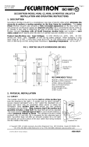
Upon unpacking this product, an inventory should be made to ensure that all the required
components and hardware have been included. Along with these instructions and the
installation template, the lock assembly (M38 Shown) should include the following items:
Mounting Bracket
Sex Bolt
Hardware Pack
Strike Plate
Magnetic Lock
Housing
PN# 500-21400
Page 2 Rev. C, 05/12
4. RECOMMENDED TOOLS
Hammer Wrench, 1/2” box-end
Center punch Pliers, vise grip
Drill motor Screwdrivers: #1 and #3 Phillips
Drill bits: 3/16”, 7/32” 3/8” and 1/2” Hex (Allen) wrenches: 1/16” (provided) & 3/16”
5. INSTALLATION INSTRUCTIONS
5.1. Pre-Installation Survey
Due to the variety of mounting configurations available with this product, it is strongly
recommended that an initial survey and assessment be made of the physical area to which
the Magnalock will be installed. A determination of the optimal method of mounting should be
made prior to installation with considerations made to the following:
A. Physical strength of mounting area. The structural integrity of mounting surfaces
must be strong enough to meet or exceed the holding force of the Magnalock.
B. Protection of the lock from external attack. The Magnalock and the wiring must be
protected to a reasonable degree from potential damage due to intruders or
vandals.
C. Convenience and accessibility of area to be protected. The Magnalock assembly
should be installed in a location that will not hinder or create a potential safety
hazard to authorized personnel routinely accessing the protected area.
The mounting configuration addressed in detail in this manual will be for an outswinging
door. All hardware required for the outswinging mount configuration has been included with
this unit. For the inswinging version of mounting, a bracket accessory Top Jam Kit (TJ-38 or
TJ-68 Series) is required. Both kits are available through Securitron. The following
illustrations show two basic mounting configurations:
Outswinging Door Mount
Inswinging Door Mount (with TJ-38 Kit)
The Magnalock should normally be mounted under the door frame header in the corner
furthest from the hinges. Most commonly the lock is positioned horizontally but vertical
orientation may also be considered. In some cases for example, the horizontal header on an
aluminum frame glass door is not as strong as the vertical extrusion, so vertical mounting
would obviously be preferred. This (outswinging) type of installation places the Magnalock on
the opposite side of the door as the door swings away from the lock. This configuration
should be used for all facility exit doors (otherwise the lock would be located on the outside
of the building). For interior doors, it is also recommended that the lock be mounted in this
manner unless security planning anticipates a physical assault on the lock from that side of
the door in which case the inswinging mounting kit (TJ-38 or TJ-68) should be obtained from
Securitron.
PN# 500-21400
Page 3 Rev. C, 05/12
5.2. Door Lock Installation
Figure 1 below is a typical cross section view of an M38 installed to a metal door frame in
the outswinging door mount configuration:
Note: Reference dimensions are in parenthesis – see the product mounting template for
clarification.
(1.50 [38.1mm] - M38)
(2.04 [51.8mm] - M68)
1.74
([44.2mm])
LOCK HOUSING
(M38 SHOWN)
LOCK MOUNT
BRACKET
5/16" STRIKE
MOUNTING SCREW
(DOOR FRAME)
(METAL)
(DOOR)
SEX BOLT
(DOOR STOP)
(2X) BLIND NUT &
1/4-20 X 1" LONG
MACHINE SCREW
(3X) #12 X 1-1/2"
LONG TYPE "A"
SCREW
STRIKE PLATE
(M38 SHOWN)
STRIKE BUSHING
(2-3X) RUBBER
WASHERS
Figure 1
5.2.1. Door Preparation
Figure 2 below is an exploded illustration of the assembly of the strike to the door:
1(X2)
2(X2)
4
5
3
6(X3)
7
Figure 2
PN# 500-21400
Page 4 Rev. C, 05/12
ITEM QTY PART
NUMBER NOMENCLATURE/DESCRIPTION
1 2 560-12050 Strike Roll Pin Bushing, Clear, Nylon
2 2 330-10800 Roll Pin, 1/4” X 1-1/4” Long, Steel (Z/P)
3 1
380-30300
775-60400 Strike Plate, M32/M38 (shown)
Strike Plate, M62/M68
4 1 330-12000 Strike Mounting Bushing, White, Delrin
5 1 300-13600
Socket Flat Head Screw, 5/16-18 UNC X 1-3/4” Long, Steel
(Z/P)
6 3 310-11100 Washer, 1” O.D. X 11/32” I.D. X 1/8” Thick, Neoprene
7 1 330-12600 Sex Bolt, 5/16-18 UNC X 1-1/2” Deep, Steel (Z/P)
5.2.1.1. Strike Installation
Using Figure 2, the template provided and the following step-by-step installation
instructions, complete the installation of the strike into the door.
1. Fold the template and place into position on door/frame at desired mounting
location. Mark the strike center hole on the door and the center position of the
two (2) slotted mounting bracket holes on the door frame.
2. Drill one (1) 3/8” [9.5mm] diameter hole through door (at mark for strike center
hole), then drill 1/2” [12.7mm] diameter through door from opposite side for
sex bolt (Item #7).
3. From the side of the door that the strike will be mounted, drill two (2) 1/2”
[12.7mm] diameter X 1-3/8” [34.9mm] deep holes for the roll pin bushings
(Item #1).
4. Insert the two (2) strike roll pin bushings into the holes in the door (either side
of strike center hole).
5. Obtain the strike (Item #3) and place on a clean, flat surface. Using a
hammer, insert and lightly tap to install the two (2) roll pins (Item #2) into
the two (2) 1/4” [6.4mm] diameter recesses of the strike. Note: Care should
be taken when installing roll pins into the strike. Excessive impact to the strike
or over-driving the pins into the recesses may distort the contact surface of the
strike which will affect the holding force of the lock.
6. Insert the strike mounting bushing (Item #4) and the 5/16-18 UNC X 1-3/4”
long socket flat head screw (Item #5) through the center hole of the strike.
7. Install two (2) of the neoprene washers (Item #6) over the screw on the
opposite side (roll pin side) of the strike. Note: A third washer is provided but
is normally not used. It may be used however, if required to take up any
additional spacing that cannot be taken up by adjusting the lock mount bracket.
8. Insert the strike mounting screw (with washers) into the 1/2” [12.7mm]
diameter strike center hole in the door while aligning the roll pins of the strike
assembly into the roll pin bushings.
9. Start the sex bolt (Item #7) into the 1/2” [12.7mm] diameter hole from the
opposite side of the door. Do not fully seat the sex bolt against the surface of
the door at this time, but thread the sex bolt onto the end of the strike
mounting screw. Using a 3/16” hex wrench, continue to thread the strike
mounting screw into the sex bolt while ensuring that the assembly maintains a
straight (perpendicular) alignment to the door.
10.Using a hammer and a 3/16” hex wrench, gradually tighten the screw into the
sex bolt until it is snug, and then tap the head of the sex bolt toward the face of
the door. Keep repeating this procedure to slowly “walk” the sex bolt into place
(head against door face) – this ensures a straight (perpendicular) alignment of
the strike assembly to the door. Note: Do not over tighten. When the strike
is fully installed there should be some play or flexing of the strike around the
washers. This allows the lock to pull the strike into the correct alignment for
maximum holding force.
PN# 500-21400
Page 5 Rev. C, 05/12
5.2.2. Door Frame Preparation
Figure 3 below is an exploded illustration of the assembly of the lock to a metal door
frame:
11 (X2)
13 (X2)
14 (X3)
8
9
12
10 (X2)
LOCK HOUSING
Figure 3
Figure 4 below is an exploded illustration of the assembly of the lock to a wood door frame:
14 (X2)
15 (X3)
8
9
12
10 (X2)
LOCK HOUSING
Figure 4
PN# 500-21400
Page 6 Rev. C, 05/12
ITEM QTY PART
NUMBER NOMENCLATURE/DESCRIPTION
8 1 (Included) Phillips Flat Head Screw, 8-32 UNC
9 1 (Included) Lock Housing Front Cover
10 2 (Included) Socket Set Screw, 6-32 UNC
11 2 320-10800 Blind Nut, 1/4-20 UNC, 1-Piece
12 1 (Included) Standard Mounting Bracket
13 2 300-12403 Phillips Pan Head Screw, 1/4-20 UNC X 1” Long, Steel (Z/P)
14 3 300-13010
Phillips Pan Head Screw, #12 X 1-1/2” Long, Type “A”, Steel
(Z/P)
15 3 300-13110 Phillips Pan Head Screw, #14 X 3” Long, Type “A”, Steel (Z/P)
5.2.2.1. Lock Installation
Using Figure 3 (for metal door frames) or Figure 4 (for wood door frames) above, the
template provided and the following step-by-step installation instructions, complete the
installation of the lock onto the door frame.
1. Locate the two (2) marks applied to the door frame for the mounting bracket
using the template in the previous strike installation section (Section 5.2.1.1,
Step 1), then:
a. For Metal Door Frame: Drill two (2) 3/8” [9.5mm] diameter holes
through the door frame at these locations.
i. Install blind nuts (Item #11) into the 3/8” [9.5mm] diameter
holes in the door frame as follows:
1. Using blind nut collapsing tool provided (with blind nut in
place), insert the end of the blind nut into the hole.
2. Using a hammer (if necessary) tap the nut in until the upper
lip seats against the door frame surface.
3. While holding the hex portion of the collapsing tool with a
1/2” box-end wrench or vise grip pliers, turn the socket head
cap screw of the tool using a 3/16” hex wrench. Note:
Maintain firm pressure toward the door frame mounting
surface while collapsing the nut.
4. Once the blind nut is adequately collapsed, remove the tool
from the nut by backing the cap screw out of the blind nut
thread.
5. Install the second blind nut onto the collapsing tool (cap
screw) and repeat sub-steps i1 through i4.
b. For Wood Door Frame: Drill two (2) 3/16” [4.8mm] diameter holes X 1-
1/4” [31.8mm] deep (minimum) into the door frame at these locations.
2. Remove the mounting bracket (Item #12) from the top (dovetail) area of the
lock housing as follows:
a. Using a #1 Phillips screwdriver, remove the 8-32 UNC flat head screw
(Item #8) holding the lock housing front cover (Item #9) in place.
Remove cover and set screw and cover aside for later assembly.
b. Using a 1/16” hex wrench, back the two (2) 6-32 UNC socket set screws
(Item #10) out far enough to allow free (sliding) movement of the
mounting bracket. Note: It is not necessary to completely remove the
set screws to allow removal of the bracket – five (5) 360-degree
counterclockwise turns is normally far enough.
c. Slide the bracket far enough to disengage the bracket from the top of the
lock housing. Note: The bracket/lock interface can be disengaged by
moving the lock (or bracket) 1” to 2” [25-50mm] laterally to one side or
the other, then withdrawing away vertically – you do not have to slide the
lock or bracket the full length of the housing to remove or install.
3. Place the mounting bracket onto the frame aligning the two (2) slotted holes in
the bracket with the previously installed blind nuts (for metal frame) or drilled
holes (for wood frame). Using a #3 Phillips screwdriver, lightly secure the
mounting bracket to the frame with:
PN# 500-21400
Page 7 Rev. C, 05/12
a. For Metal Door Frame: Two (2) 1/4”-20 UNC X 1” long Phillips pan head
screws (Item #13) provided.
b. For Wood Door Frame: Two (2) #12 X 1-1/2” long Phillips pan head
type “A” screws (Item #14) provided.
Note: Do not fully secure (tighten) the screws at this point. Tighten
screws to “snug” and back out as necessary to provide slight movement
of bracket for adjustment.
4. Assemble the lock housing to the bracket by inserting and engaging the top
(dovetail) feature of the lock with the mounting bracket. Slide the lock into
proper position (centered on the mounting bracket).
5. Adjust the lock/bracket assembly in the slots of the bracket as necessary to
establish proper relationship with (against) the strike.
6. Carefully remove the lock housing from the mounting bracket while attempting
not to alter the position of the bracket on the door frame.
7. Using a #3 Phillips screwdriver, fully secure the two (2) screws (Item #13 or
#14) installed in Step 3 above.
8. Using the installed mounting bracket as a guide, locate and drill three (3) holes
into the door frame corresponding to the remaining three (3) open holes in the
bracket:
a. For Metal Door Frame: Drill three (3) 3/16” [4.8mm] diameter holes
(through).
b. For Wood Door Frame: Drill three (3) 7/32” [5.6mm] diameter holes X
2-3/4” [69.9mm] deep (minimum).
9. Using a #3 Phillips screwdriver, install the three (3) #12 screws (Item #14 for
metal frame) or #14 screws (Item #15 for wood frame) through the bracket
and into the holes in the door frame. Tighten the screws to secure the mounting
bracket to the door frame.
10.Determine optimal location then drill a 3/8” [9.5mm] diameter hole through the
door frame for the lock power cable. Note: This hole must align within the
large slotted “window” in the top of the lock housing when the lock is installed
on the mounting bracket.
11.After all electrical wiring has been completed, install the housing front cover
(Item #9) and secure in place using the 8-32 UNC flat head screw (Item #8).
5.3. Lock with “D” (Door Position) Option - Installation
For locks provided with the “D” (Door Position) option, the magnetic (reed) switch is factory
installed inside the control wiring access compartment cover.
When a lock has been previously installed and it has been later determined to upgrade to the
“D” option in the field, the template provided in the upgrade kit illustrates proper location and
installation of the switch to the inside of the compartment access cover.
Using Figure 5 below, the template provided and the following step-by-step installation
instructions complete the installation of the actuator block to the door adjacent to the strike
plate.
1. After marking the mounting holes for the actuator block on the door using the
mounting template provided with the lock (or upgrade kit), center punch these
locations. The actuator block has hardware included for mounting in two types
of configurations. Decide which of the following choices will work best for the
application and then:
a. If Mounting Using #8 Flat Head Screws (Recommended for Solid
Core (Wood), Aluminum Frame or Hollow Metal Doors): Drill two
(2) 9/64” [3.6mm] diameter holes X 3/4” [19.1mm] deep (maximum)
into the door at the center punched locations or;
b. If Mounting Using #6 Pan Head Screws (Recommended for
Aluminum Frame, Hollow Metal or the Top Jam Z-Bracket): Drill
two (2) 1/8” [3.2mm] diameter holes X 3/8” [9.5mm] deep (maximum)
into the door at these locations.
PN# 500-21400
Page 8 Rev. C, 05/12
2. Using a #1 Phillips screwdriver and the screws provided secure the actuator
block to the door making sure that the arrow of the label on the backside of
the block is facing toward the mounting edge of the lock.
(Reference)
Strike mounted to door
See Section 5.2.1
(Figure 2)
Mark & drill holes in door for
Actuator Block mounting in
accordance with installation
template (P/N 500-61050)
Ensure arrow indicator of label
(on backside) of Actuator Block
is facing toward the mounting
edge of the lock when installing!
Actuator Block
Phillips Flat Head Screw #8 X 1-1/2" Long,
Type "A", Steel, Zinc Plated (2X) OR
Phillips Pan Head Screw #6 X 3/4" Long,
Type "A", Steel, Zinc Plated (2X) (Not Shown)
Figure 5
5.4. Inswinging Door Lock Installation
As previously mentioned, additional hardware and brackets are required for mounting the
lock system in the inswinging door configuration. The brackets, hardware and instructions
required for the installation of the lock in this arrangement are available in a Top Jam Kit (TJ-
38 or TJ-68 Series) which may be obtained through Securitron Magnalock Corporation or one
of our authorized representatives.
6. OPERATIONAL INSTRUCTIONS
The M38/68 series Magnalocks are direct holding fail safe electromagnetic locks. Both
incorporate Securitron’s unique dual voltage system. Simply apply 12 or 24 volts DC observing
polarity (See Figure 6) and the locks will energize to their respective holding forces of 600 lbs.
[272 Kg] for the M38 and 1200 lbs. [544 Kg] for the M68.
The “L” option adds the ability to visually inspect the lock and determine via a red LED that the
lock is in fact energized.
The addition of the “S” option provides a lock status sensing signal which indicates that the lock
is secure and gives you the added ability of a SPDT dry contact that you can interface to either
the access control system or intrusion detection system (See Figure 7). The “S” option will
only report the door is secure if two criteria are met. One - the lock must be powered and two -
the strike armature must be in full unobstructed contact with the lock face.
Add the two options together “LS” and get both the dry contact output and a visual reference
via a bi-color LED (red = door powered and locked, green = door powered but not locked and off
= door not powered or locked).
PN# 500-21400
Page 9 Rev. C, 05/12
Figure 6
Figure 7
The addition of the “D” option incorporates a door position sensing switch which indicates when
the door is outside of the sensing range of the lock (3/8”-3/4”) and provides the added ability of
a SPDT dry contact that can be interfaced with either an access control system or intrusion
detection system (See Figure 8). The “D” option will report the door position whether the lock
is powered (secured) or not.
NC
C
NO
IN
REF
SERIES M38 OR M68 WITH "D" OPTION
(DOOR POSITION SWITCH)
(RED)
(WHITE)
(BLUE)
ACCESS CONTROL SYSTEM
DOOR POSITION STATUS INPUT
"D" OPTION OUTPUT
SPDT DRY CONTACT
CONTACT RATING: 200 mA @ 24 Volts
Figure 8
The “T suffix option implements a small micro switch to create a tamper resistant enclosure of
the control wiring access compartment. At approximately .03” movement of the access cover
away from the lock housing (usually less than a full turn of the mounting screw) a signal is
transmitted to indicate that access is being attempted to the lock control wiring compartment.
(See Figure 9 for wiring diagram).
PN# 500-21400
Page 10 Rev. C, 05/12
NC
C
NO
IN
REF
SERIES M38 OR M68 WITH "T" OPTION
(TAMPER INDICATION SWITCH)
ACCESS CONTROL SYSTEM
LOCK TAMPER STATUS INPUT
(RED)
(WHITE)
(BLUE)
"T" OPTION OUTPUT
SPDT DRY CONTACT
CONTACT RATING: 2 Amps @ 24 Volts
Figure 9
The “OS” suffix option available for M68 series locks provides a modified “Offset” strike to shift
the strike contact face 1/4” [6.4mm] further away from the door frame stop than the standard
strike. This can be helpful in the installation to aluminum frame glass doors where the height of
the aluminum rail at the top of the door is not sufficiently wide enough to accommodate the
standard sex bolt/strike installation. It should be noted that an approximate 10% loss in holding
force results from the use of this strike because of its offset position however, this should not be
significant in that aluminum frame glass doors are not high security barriers. The offset strike is
included with locks ordered with the “OS” suffix or may be ordered separately.
A “Split Strike” configuration option is available for M68 series locks ordered with the “SS”
suffix. This allows one lock to be used to secure two doors in a double door configuration. In
this method, a single Magnalock is mounted near the center of the header and a half size strike
is provided for mounting to each door/leaf. This arrangement will also reduce the holding force
to about 550 Lbs. (250Kg) per door/leaf. Locks ordered with the “SS” suffix include the two
(split) strikes or they may be supplied separately.
7. MAINTENANCE
To keep the Magnalock in top working order, especially a Magnalock equipped with the “S
(Senstat) option, we recommend taking a clean cloth and rubbing alcohol or a non-abrasive
cleaner and wiping down the face of the Magnalock and the strike once every six months.
PN# 500-21400
Page 11 Rev. C, 05/12
8. APPENDICES
A. WIRE GAUGE SIZING
If the power supply is distant from the lock, voltage will be lost (dropped) in the connecting
wires so that the Magnalock will not receive full voltage. The following chart shows the
minimum wire gauge that will hold voltage drop to an acceptable 5% for different lock to
power supply distances. Proper use of the chart assumes a dedicated pair of wires to power
each Magnalock (no common negative). Note that a Magnalock operating on 24 volts is a
much better choice for long wire runs as it has 4 times the resistance of a 12 volt installation.
Also note that the correct calculation of wire sizing is a very important issue as the installer is
responsible to insure that adequate voltage is supplied to any load. In multiple device
installations, the calculation can become quite complex so refer to the following section
“Calculating Wire Gauge Sizing” for a more complete discussion.
Distance Gauge 12V Gauge 24V
100 FT 24 GA 24 GA 800 FT 18 GA 22 GA
200 FT 22 GA 24 GA 1500 FT 14 GA 18 GA
400 FT 20 GA 22 GA 2000 FT 14 GA 18 GA
CALCULATING WIRE GAUGE SIZING
The general practice of wire sizing in a DC circuit is to avoid causing voltage drops in
connecting wires that reduce the voltage available to operate the device. As Magnalocks are
very low power devices, they can be operated long distances from their power source. For any
job that includes long wire runs, the installer must be able to calculate the correct gauge of
wire to avoid excessive voltage drops.
This is done by taking the current draw of the lock and multiplying by the resistance of the
wire I x R = Voltage drop (i.e. 0.100A x 10.1 Ohms = 1.01 Volts dropped across the wire). For
all intents and purposes it can be said that a 5% drop in voltage is acceptable so if this were a
24 Volt system (24 Volts x .05 = 1.2 Volts) a 1.01 Volt drop would be within tolerance.
To calculate the wire resistance, you need to know the distance from the power supply to the
Magnalock and the gauge (thickness) of the wire. The following chart shows wire resistance
per 1000 ft (305 meters):
Wire Gauge Resistance/1,000 ft
8 Gauge .6 Ohms 16 Gauge 4.1 Ohms
10 Gauge 1.0 Ohms 18 Gauge 6.4 Ohms
12 Gauge 1.6 Ohms 20 Gauge 10.1 Ohms
14 Gauge 2.5 Ohms 22 Gauge 16.0 Ohms
B. CONSIDERATIONS FOR MAXIMUM PHYSICAL SECURITY
M38 and M68 Magnalocks carry rated holding forces of 600 lbs. [272 Kg] and 1,200 lbs. [544
Kg] respectively. There are several installation and application variables to be considered
which affect the security level that may be obtained while using a Magnalock.
In the case of wooden doors (other than solid hardwoods), aluminum frame glass doors, and
hollow metal doors, the M38 should be employed in a “traffic control” mode. This is because a
determined assault on these types of door/lock configurations has the potential of “popping
this model open. The M68 is generally stronger that the door itself. Users have logged
periodic cases of an assault where the door has been destroyed leaving the Magnalock intact
and still retaining the piece of the door where the strike was mounted.
A pry bar may be used to try to pry the door open. However, what generally occurs is that the
door will experience material failure. The pry bar tears (in the case of wood) or bends (metal)
the door material without defeating the lock. The general fact that a Magnalock mounts on the
other side of the door from the attacker is an important contributor to its strong resistance to
assault.
The concept of preferring a door that gives also affects the issue of physical security on
different door types. Oddly enough, the characteristics that make an inswinging door strong
PN# 500-21400
Page 12 Rev. C, 05/12
can make it more difficult to secure if it is stiff or rigid. Steel doors and most particularly solid
steel doors such as may be found in prisons, transmit impact much more effectively to the lock
and as such may be defeated by repeated leg blows or by charging the door. If the end user
has such doors and/or a security environment where such determined attacks can be foreseen
on the doors, it is his responsibility to ensure that the Magnalock’s strength is adequate for the
application. Selection of the model 68 is strongly recommended with another technique being
the use of multiple locks.
These Magnalocks have been carefully designed to be installed with the included fasteners
which substantially exceed the strength of the lock. If the installer substitutes for any of the
factory included fasteners or hardware for any reason, the strength capability of the
installation may be compromised. It should be noted that a key component to the successful
installation of this product is the sex bolt. The head of the sex bolt is the only part of the lock
assembly that is accessible to an attacker.
It is also vital when mounting the magnet (lock housing) into a metal frame to use the
included machine screws and steel blind nuts. An alternative technique has been to use sheet
metal screws which some installers feel is easier. This is extremely ill advised as the magnet
receives a torquing force each time that the door is closed, which over time will work the sheet
metal screws loose. It has been determined that sheet metal screws may be considered
acceptable, although not preferred, if the frame header is made of steel. Indeed this is
mandated when Securitron’s concrete header bracket is utilized. On an aluminum header
however, mounting with sheet metal screws is dangerous as the steel screw threads will
eventually tear through the relatively soft aluminum.
To fully complete an installation that maximizes the effectiveness of the included fasteners, the
thread locker compound (provided) should be used to prevent the threads from loosening over
time.
PN# 500-21400
Page 13 Rev. C, 05/12
C. TROUBLESHOOTING
PROBLEM: No magnetic attraction between magnet and strike plate.
First be sure the Magnalock is being correctly powered with DC voltage. This includes
connecting the power wires with correct polarity. Positive must go to red and negative to
black. If the magnet body is wired in reverse polarity, it will not be damaged, but it will not
operate. If the unit continues to appear dead, it must be electrically checked with an
Ammeter. It must be powered with the correct input voltage and checked to see if it draws the
specified current. If the unit meters correctly, it is putting out the correct magnetic field and
the problem must lie in the mounting of the strike.
PROBLEM: Reduced holding force.
This problem usually expresses itself in terms of being able to kick the door open or to open it
with a shoulder. Check the strike and magnet face to see if some small obstruction is
interfering with a flat fit. Even a small air gap can greatly reduce the holding force. Another
possibility is if the strike plate has a dent on it from being dropped for example. Remove the
strike from the door and try to rock it on the magnet face to insure that it is flat. If the strike
and magnet are flat and clean, the cause is nearly always improper mounting of the strike in
that the strike is mounted too rigidly. The strike must be allowed to float around the rubber
washer stack which must be on the strike center mounting screw. The magnet then pulls it
into flat alignment. To correct the problem, try loosening the strike mounting screw to see if
the lock then holds properly. Another possibility is if you are operating the lock on AC instead
of DC or on half wave rectified DC (transformer + single diode). Half wave rectified DC is
unacceptable; you must at a minimum employ full wave rectified DC (transformer + bridge).
PROBLEM: The Senstat output does not report secure.
Because of the simplicity of Securitron’s patented Senstat design, this is almost always a case
of the lock status sensor doing its job. It is not reporting secure because a small obstruction
or a too stiffly mounted strike is causing the Magnalock to hold at a reduced force. The
problem is corrected by cleaning the surfaces of the magnet and strike (see Maintenance
Section 7) or establishing proper play in the strike mounting. If this does not work, you can
verify function of the Senstat feature as follows: Note that there are two (2) thin vertical lines
on the magnet face that can be said to separate the core into three (3) sections from left to
right. The Senstat output is created by the strike establishing electrical contact between the
leftmost and rightmost core segments. With the lock powered, use a pair of scissors and press
the points respectively into the leftmost and rightmost core segments. The Senstat output
should then report secure. This shows that the problem lies in the strike not making correct
flat contact with the magnet face. If the scissors technique does not cause the lock to report
secure, check to see if there is a broken Senstat wire. If this is not the case, the lock must be
returned to the factory for replacement.
PROBLEM: The lock does not release.
When power is removed from it, the Magnalock must release. Therefore the complaint of "lock
will not release" is either mechanical bonding via vandalism or a failure to completely release
power. By mechanical bonding, we simply mean that glue has been applied between the strike
plate and magnet as a prank. Failure to completely release power is generally a wiring
integrity problem. What happens is that an upstream switch removes power from the wires
going to the Magnalock, but through an installation error, the wires have their insulation
abraded between the switch and lock so that partial or full power can leak in from another
Magnalock or other DC device with similarly abraded wiring. This is most likely to occur at the
point where the wire cable leaves the Magnalock case and enters the door frame. Another
area is via an improper splice on wiring in conduit. Either a metal door frame or the metal
conduit is capable of leaking power between multiple devices with abraded wires, thereby
bypassing switches. A good way to check this electrically (as opposed to visually removing and
inspecting the wires) is to use a meter and check for leakage between the power supply
positive or negative and the door frame and conduit. Magnalocks should be powered by
isolated DC voltage without any earth ground reference to positive or negative.
PROBLEM: The lock rusts.
Both the magnet core and strike plate are plated and sealed following a military specification.
If rusting appears, the most common cause is that improper cleaning (with steel wool for
instance) has occurred and this has stripped off the relatively soft plating. Once the plating
PN# 500-21400
Page 14 Rev. C, 05/12
has been removed, it cannot be restored in the field, so the lock will have to be periodically
cleaned and coated with oil or other rust inhibitor. A rusty Magnalock will still function but at
reduced holding force. If the product is installed in a heavily corrosive atmosphere, such as
near the ocean, it will eventually rust even with non-abrasive cleaning. The only answer then
becomes continued periodic removal of the rust.
PROBLEM: Apparent electronic noise interference with the access control system.
Electric locks, being inductive devices, return voltage spikes on their power wires and also emit
microwave radiation when switched. This can interfere with access control electronics causing
malfunctions. Access control contractors often employ installation techniques designed to
isolate the access control electronics from the electric lock. These include separate circuits for
the lock, shielded wiring and other techniques. These techniques will vary with the sensitivity
of the access control system electronics and should, of course be followed. Note that
Magnalocks include internal electronics which suppress both inductive kickback and radiation.
They have been extensively tested and accepted by numerous access control manufacturers
and have been used in thousands of installations without incident. An apparent noise problem
is therefore usually not caused by the Magnalock. The access control equipment may be itself
faulty or have been installed improperly. One problem can arise with the Magnalock. If the
Senstat version is being used, the strike plate (which passes current) must be isolated from a
metal door and frame. Securitron supplies insulating hardware to accomplish this but the
hardware may not have been used or the strike may be scraping against the header for
instance. Check for full isolation between the strike and the door frame (when the door is
secured) with an Ohmmeter. The presence of lock voltage potential in the door frame can
interfere with the ground reference of access control system data communication and therefore
cause a problem.
IF YOUR PROBLEM PERSISTS
CALL SECURITRON TOLL FREE
1-800-MAG-LOCK
9. MAGNACARE LIFETIME REPLACEMENT WARRANTY
For warranty information visit www.securitron.com/en/site/securitron/About/MagnaCare-Warranty/
  • Page 1 1
  • Page 2 2
  • Page 3 3
  • Page 4 4
  • Page 5 5
  • Page 6 6
  • Page 7 7
  • Page 8 8
  • Page 9 9
  • Page 10 10
  • Page 11 11
  • Page 12 12
  • Page 13 13
  • Page 14 14

Assa Abloy Securitron M38L Installation guide

Type
Installation guide

Ask a question and I''ll find the answer in the document

Finding information in a document is now easier with AI