Page is loading ...

Installation Instructions CF830CA-QRG
Issue Date March 14, 2023
Single Stage HSI, IFC, 3 Speed Fan Replacement Kit
© 2023 BASO Gas Products 1
Part No: QRG Instruction. BASO-INS-CF830C-QRG, Rev. C www.baso.com
CF830CA - Single Stage HSI Integrated Furnace Control,
3 Speed Fan Replacement Kit
Quick Reference Guide
The CF830CA Integrated Furnace Control Board is an embedded microprocessor-based system designed for the
automated control for a Carrier Force Air Furnace and is a direct replacement for the HK42FZ014 control board.
CARRIER: HK42FZ014, other circuit board numbers included: CEPL130437-01, CEBD430437-09A,
HK42FZ0142411, HK42FZ0143215, 00662442334763, CEPL1300437-01-I
FEATURES
• 24 VAC dual microprocessor-based design with a focus on safety
• Controls Gas Valve, Hot Surface Igniter, Circulator Fan, Inducer Motor, Humidifier, Dehumidify and Electronic
Air Cleaner (EAC)
• Designed for 100% gas valve shutoff in case of ignition failure
• Full time flame sensing
• Reverse polarity protection and detection
• Secondary brown-out voltage protection
• Compatible with standard 24VAC thermostat, as well as smart thermostats
• Provides tri-color diagnostic STATUS LED and Flame Status LED to aid in troubleshooting
• Twinning compatible with other CF830CA control boards
• 3 Speed FAN Control
• 2-year warranty

Single Stage HSI, IFC, 3 Speed Fan Replacement Kit
2023 BASO Gas Products 2
Part No: BASO-INS-CF830CA-QRG, Rev. C www.baso.com
Specifications
Input Voltages:
120 VAC (98 - 132 VAC) 50 / 60 Hz
24 VAC (18 – 30 VAC) 50 / 60 Hz
Input Current:
0.3 A max. with all outputs de-energized
On Board Fuse:
3 Amp (Automotive Style Fuse)
Ignitor Relay:
6 A @ 120 VAC (resistive)
Circulator Fan Relay (Heat/Cool):
12 FLA - 30 LRA @120 VAC
Inducer Relay:
4 FLA – 8.0 LRA @ 120 VAC
Gas Valve:
2 A @ 30 VAC
Electronic Air Cleaner (EAC):
1 A @ 120 VAC
Humidifier (HUM):
0.5 A @ 30 VAC
Dehumidifier Input (DHUM)
Flame Current Minimum Flame Detection:
0.1 uA DC
Flame Failure Response Time:
1.0 second maximum
Operating Temperature:
-40 to 176°F (-40 to 80°C)
Humidity:
0% to 95% RH (non-condensing)
Lockout Recovery:
Cycle Power
Flame Status LED:
Amber LED, on Flame Sense, Off No Flame
Status Code LED:
Green, Red, LED for troubleshooting
Timings
Pre-Purge:
15 sec.
Initial Ignitor Warm Up:
17 sec.
Trial for Ignition Period:
5 sec.
Trial for Ignition Activation Period:
2 sec.
Retries:
4 trials
Flame Loss Period:
90 sec
Post-Purge Period:
Heat Delay-To-Fan-Off selected time
Inducer Purge Period:
5 sec.
Heat Delay – To – Fan – On:
25 sec.
Heat Delay – To – Fan – Off:
90/120/150/180 sec. J1 selectable
Cool Delay – To – Fan – On:
2 sec.
Cool Delay – To – Fan – Off:
90 sec. (J2 Uncut) 5 sec. (J2 Cut)
Soft Lockout Time:
180 min.
Hard Lockout Time:
Power Reset
Agency Certifications
C22.2 No 60730-2-5-14/
ANSI Z21.20-14
File: C333501

Single Stage HSI, IFC, 3 Speed Fan Replacement Kit
2023 BASO Gas Products 3
Part No: BASO-INS-CF830CA-QRG, Rev. C www.baso.com
Electrostatic Discharge (ESD) Precautions
When handling electronic devices, it is important to be cautious of electrostatic discharge (ESD). ESD can impact
electronic components which may damage the CF830CA board immediately or weaken components in the future.
The following precautions should be followed, to prevent ESD from damaging the CF830CA Control Board:
1. Disconnect power to the furnace.
2. Discharge yourself, touch your hands and tools to a clean unpainted metal surface on the furnace.
Periodically Discharge yourself during the replacement.
3. Prior to touching the CF830CA, ground yourself again to prevent damage to the control board. Hold
CF830CA board by its edges.
4. ESD damage can be prevented by using an ESD grounding strap.
Removing Existing Control Board
1. Prior to disconnecting wires, label or identify all wires or snap a picture of wiring on existing board. Miswiring
may result in dangerous operation, or damage to control.
2. Turn thermostats to the “OFF” position or lowest temperature setting.
3. Disconnect the electrical supply to the furnace.
4. Disconnect the gas supply from the furnace.
NOTE: Failure to correctly remove the gas supply and/or electrical supply from the furnace can
result in explosion, fire, death, or personal injury.
5. Disconnect thermostat and humidifier wires (where applicable).
6. Disconnect line voltage, blower, transformer, and (EAC) wires (where applicable).
7. Remove the wiring harness connections from the control.
8. Examine control for signs of water leakage and excessive charring on the control.
9. If necessary, repair any water leaks, being sure to check humidifiers, evaporator coils, and vents near the
control.
Installation of New Control Board
1. Use existing plastic snap in frame, from the existing control, to mount CF830CA control board or if required,
use the provided template, and drill four 0.187” or 3/16” holes into the control box, deburr and clean.
2. Ground yourself to remove any ESD on your body before handling the CF830CA Control Board. When
handling control board hold it by the edges.
3. Insert double ended standoffs into the 4 outside corner holes of the Control board. Also snap in support
standoffs to secure board from flexing.
4. Insert the CF830CA Control Board via the 4 standoffs in the corners into the newly drilled holes on the
furnace control box panel.
5. Install wiring harness.
a. The 11-pin connector connects to (PL1) on the furnace control board.
b. The 2-pin connector connects to (PL2) on the furnace control board.
c. The 2 single white wires connect to (NEUTRAL) spade terminal.

Single Stage HSI, IFC, 3 Speed Fan Replacement Kit
2023 BASO Gas Products 4
Part No: BASO-INS-CF830CA-QRG, Rev. C www.baso.com
6. Connect the transformer to the CF830CA;
a. Blue wire to the (SEC-2) spade terminal.
b. Red wire to the (SEC-1) spade terminal.
c. Black wire to the (PR-1) spade terminal.
d. White wire to the (NEUTRAL) spade terminal.
7. Connect Furnace Main Power Junction box;
a. Black wire to the (K1-L1) Blower Relay Common spade terminal.
b. White wire to the (NEUTRAL) spade terminal.
8. Connect the Blower motor to the CF830CA;
a. White wire to the (NEUTRAL / BLW) 3/16” spade terminal area.
b. Heat wire speed tap to terminal labeled (HEAT) of K7 relay.
c. Cool wire speed tap to terminal labeled (COOL) of K7 relay.
d. Fan wire speed tap to terminal labeled (FAN) of K2 relay.
e. Connect remaining Blower wires to (SPARE-1), (SPARE-2) if applicable.
9. Connect any HUM, EAC, etc. be sure to follow Manufactures installation procedures.
10. Re-install the control box along with the CF830CA into the furnace.
11. Re-position any wiring/harnesses that may interfere with the control of the furnace.
12. Set BLOWER OFF DELAY (J1) jumper if needed, default value is 120 seconds.
13. Set the P9 Header to “NO VALVE SENSE” if needed, open contacts are in series with the gas valve.
(Typical LP fired furnaces)
14. Replace old wiring diagram with included new wiring diagram decal.
15. Place CF830C/CA Service Code decal on the furnace near the control and visible for tech.
16. Do not connect the thermostat wires until system tests have been completed.
System Tests
Step 1: Component Self-Test
1. With the thermostat turned to the OFF position or the thermostat wires disconnected from the CF830CA
control board, turn power on and manually close the door switch. With a length of wire, momentarily short
(.5 to 3 sec.) the TEST/TWIN terminal to 24VAC Common.
2. The Self-Test will now begin, and the following sequence of actions will be performed:
a. Self-Test red led error code will be displayed, Inducer motor ON for entire test.
b. The Hot Surface Igniter will turn on for 15 seconds.
c. The blower motor fan speed will turn on for 10 seconds.
d. The blower motor heat speed will turn on for 10 seconds.
e. The blower motor cool speed will turn on for 10 seconds.
NOTE: The Gas Valve WILL NOT be enabled during the self-test.
3. Resolve any issues with components that don’t operate correctly in self-test period.
4. Power off the control and release the door switch.
5. Connect thermostat wires, install the blower and access doors, turn power and gas On.
Step 2: Flame Sensor Operation
1. Connect a multimeter set to DC microamps in series with the flame sense rod.
2. Using the thermostat, initiate a call to heat. Burner Ignites and stabilizes.
3. Measure Flame Current (FC). Nominally FC is between 0.1 and 1.0 microamps DC.

Single Stage HSI, IFC, 3 Speed Fan Replacement Kit
2023 BASO Gas Products 5
Part No: BASO-INS-CF830CA-QRG, Rev. C www.baso.com
4. If FC is less than 0.1 microamps DC, either check the wiring to the flame sense rod or replace the flame
sense rod, or clean the flame sense rod using steel wool.
5. Flame present, verify Amber color Flame Status LED is ON indicates presence of flame.
Step 3: System Operation
1. Perform safety checks where applicable, Flame Rollout, limit switch, and vent system.
2. Operate the control through an entire call to heat cycle 3 to 5 times to insure proper operation.
Operation; Call for Heat
Thermostat Call For Heat (CTH), starts the control heating sequence. The control conducts a safe start check test
first checking hardware and software conditions, and verifies that the pressure switch contacts are open. Control
then turns on the output to the Inducer blower and waits for a pressure switch closed signal, once closed control then
enters a pre-purge period of 15 seconds, and then sends an output to the Hot Surface Igniter (HSI) for 17 seconds
for a warmup period. The Gas Valve is enabled after the warmup period allowing Gas to flow across the HSI for a
period of 5 sec. The HSI is disabled and the control verifies the integrity of the flame for 2 seconds. If flame is
detected the control then enters the wait for heat fan on delay time of 25 sec. which then enables the blower motor at
heat speed and also energizes the EAC outputs and puts the control in the run mode. Once call for heat is satisfied
the control de-energizes the gas valve and inducer blower. The control begins the heat delay to off period for the
blower, upon completion of blower delay time. The Blower and EAC outputs are de-energized. The control then
returns to an idle state waiting for the next call for heat, call for fan, or a call to cool.
Abnormal Flame-Proving Signal
In the event an Abnormal Flame-Proving signal is detected in a state where flame should not be present. The control
will enable the inducer motor output and will be indicated by a red error code of Abnormal Flame-Proving Signal.
Once the flame signal is lost the inducer will shut off after a 5 sec. purge period and the unit will begin normal
operation again.
In the event a flame is not sensed when a flame should be present in the following states:
1. Flame not present during Ignition or Flame Proving period: The control will immediately begin a new trial
starting at checking for the pressure switch to be open, pre-purge time, HSI warmup time, valve energized
time and Flame proving time. The unit will display a red Ignition Failure error code at this time. Control will
repeat this cycle 4 times. If flame is proven during any retry cycle, the control will go back to a steady green
OK status light. If no flame is proven, control will go into a soft lock out for 180 minutes and retry again,
Inducer motor will be on the entire lock out time.
2. Flame not present during Wait for Heat Fan on Delay or Run mode: The control will call the heating trial a
failed trial and display a red Ignition Failure error code. The control will begin with a Post-Purge period of 5
sec. (blower is enabled at heat speed and the inducer motor is allowed to run) then inter-purge period of 90
sec. begins. After Inter-Purge period expires the Control will then proceed with the standard startup routine as
listed in Operation Call for Heat. Control will repeat this cycle 4 times before going into a soft lockout for 180
minutes and retry again.
Operation; Call for Cooling
Thermostat calls for cooling turning on the CF830CA and the AC compressor. The Cool Delay to Fan On period
begins which is 2 seconds. After the delay is elapsed the circulator fan is energized at cool speed and the (EAC)
output is energized. Once the thermostat is satisfied the AC compressor is de-energized and the Cool Delay to Fan
Off period is activated for 90 seconds. After the Cool Delay to Fan Off period has elapsed the circulator fan and the
EAC outputs are de-energized.

Single Stage HSI, IFC, 3 Speed Fan Replacement Kit
2023 BASO Gas Products 6
Part No: BASO-INS-CF830CA-QRG, Rev. C www.baso.com
Operation; Manual Fan on Mode
When the thermostat fan switch is moved to the on position, the control will activate the blower at Fan or low speed
and the EAC output. A Call for Heat or a Call for Cooling will override the Manual Fan operation.
Blower Delay Timing Configuration
The Heat Delay to Fan Off Time can be changed via moving the Jumper (J1).
The Cool Delay to Fan Off time can be changed via Jumper wire (J2). J2 uncut is 90 sec. delay, and J2 cut is 5 sec.
delay period.
Twinning Instructions
A 3/16” quick connect terminal is present on the CF830CA Furnace Control Board to provide a signal to another
CF830CA Furnace Control Board for furnace twinning. In order to configure two CF830CA controls for twinning:
1. Install each control following the above instructions.
2. Connect the TWIN terminals on the two controls.
3. Connect the 24VAC Common (COM 24V) and Thermostat (W) wires together on the two controls.
If the supplies are in phase, both furnaces will turn the blower on and off according to the thermostat inputs, and the
blower being enabled on one board. If the supplies are not in phase, the STATUS LED will flash red rapidly.
Fuse 3 Amp Automotive Style
The CF830CA Control has only 1 serviceable component, an automotive style 3 Amp fuse.
CF830CA Diagnostic Feature
The CF830CA control is continuously monitoring your furnaces performance and will indicate any abnormal behavior
or sequence that occurs. Problems that occur with your furnace will be translated into visual Led color and light
pattern that can be decoded by the CF830CA Service Code Label.
NOTE: For more detailed installation instructions on BASO’s Furnace Control please visit us at
www.baso.com.
Important: Preventative maintenance programs are an important part of maintaining optimum and safe function of
your BASO Products. Any attempt to repair this assembly voids the manufacturers 2-year warranty. For replacement
module, contact the original equipment manufacturer or nearest BASO GAS Products distributor.
BASO GAS PRODUCTS LLC 1-877-227-6427 (1-877-BASOGAS)
450 East Horseshoe Rd. Published in the USA
PO BOX 170
Watertown, WI 53094

Single Stage HSI, IFC, 3 Speed Fan Replacement Kit
2023 BASO Gas Products 7
Part No: BASO-INS-CF830CA-QRG, Rev. C www.baso.com
Troubleshooting Guide Red Status LED
Flash
Code
Error Condition Possible Cause Lockout Type
1 + 1 Component Self-Test See (System Tests Component Self-Test) None
1 + 2 Blower on at Power Up Thermostat Calling for Heat on Power Up. None
1 + 3 Limit or Roll-out Lockout
Check Limit Switch and Rollout switch for
proper contact operation.
Soft Lockout
Recovery after 3-hour Period or Cycle
power
1 + 4 Ignition Lockout Pressure Switch check if opens and
closes, Inducer motor for proper
operation, Flame sense Rod.
Soft Lockout
Recovery after 3-hour Period or Cycle
Power
2 + 0 Input Voltage Low Low 24 VAC Input Voltage check
transformer. Standby
Auto Reset when corrected
2 + 1 Gas Heating Lockout
Gas Valve, Check wiring and coil
resistances. Check for N.O. contacts in
series with gas valve, move valve sense
jumper on P9 to “NO VS” position.
Hard Lockout
Cycle Input Power On / Off / On
2 + 2 Abnormal Flame-Proving
Signal Gas Valve Stuck or leaking, Flame Sense
Rod. Standby
Auto Reset when corrected
2 + 3 Pressure Switch Did Not
Open
Venting Sizing or Restriction, Inducer
Motor not turning off, Pressure Switch
Contacts, Air Supply.
Standby
Auto Reset when corrected
3 + 1 Pressure Switch Did not
close or reopen
Venting Sizing or Restriction, Inducer
Motor not turning off, Pressure Switch
Contacts, Air Supply.
Standby
Auto Reset when corrected
3 + 2 Self-Checked Failed Gas Valve wiring or Internal Control board
failure. Hard Lockout
Cycle Input Power On / Off / On
3 + 3 Limit or Roll-out Switch
is Open
Blower Motor, Blower Motor Starter
Capacitor, Roll out Switch Fusible link,
Dirty Air Filter, Defective Switch or bad
connection.
Soft Lockout
Recovery after 3-hour Period or Cycle
Power
3 + 4 Ignition Failure Manual Gas Shut-off valve closed, Gas
valve closed, Flame rod dirty or defective,
Low Inlet Gas Pressure.
Standby
Auto Reset when corrected
3 + 5 Voltage/Frequency
Standby Low or High 24 VAC input voltage or
Frequency. Standby
Auto Reset when corrected
Solid
Red Ground Sense / Reverse
Polarity Error 24 VAC Common, 115VAC line and
Neutral reversed, Ground Wiring Hard Lockout
Cycle Input Power On / Off / On
Rapid
Flashing Twinning Error Twinning Wiring not correct, 24 VAC
Common lead Wiring, 120 VAC Line and
Neutral reversed, Ground Wiring.
Standby
Auto Reset when corrected

Single Stage HSI, IFC, 3 Speed Fan Replacement Kit
2023 BASO Gas Products 8
Part No: BASO-INS-CF830CA-QRG, Rev. C www.baso.com
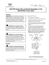
Wiring Diagram
/