Page is loading ...

Installation Instructions C610UQRG
Issue Date June 28, 2018
24 VAC Universal Intermittent Pilot Gas Ignition Control
©2018 BASO Gas Products 1
Part No. BASO-INS-C610UQRG, Rev. C www.baso.com
24 VAC Universal Intermittent Pilot Gas Ignition Control
Quick Reference Guide
The C610U Universal Intermittent Pilot Gas Ignition Control module replaces many popular
flame rectification type of intermittent pilot ignition (IPI) modules, including those manufactured
by Honeywell, Robert Shaw, ICM, Fenwal, and Johnson Controls.
The following is an overview of the C610U series control, and is intended to only be used by
Certified Service Technicians.
APPLICATION
Gas Furnaces
Boilers
Water Heaters
Commercial Cooking
FEATURES
24 VAC microprocessor based IPI control
System diagnostics
32 Selectable preset timings of popular models
Universal flame sensing (Local/Internal or Remote/External)
Full time flame sensing
Flame sense test pins
4 mounting hole positions, 2 that match Honeywell and Fenwal
Built-in burner ground
Voltage/Frequency monitoring

24 VAC Universal Intermittent Pilot Gas Ignition Control
©2018 BASO Gas Products 2
Part No. BASO-INS-C610UQRG, Rev. C www.baso.com
SPECIFICATIONS
Input Voltage
Control: 24 VAC(18-30 VAC) 50/60 Hz
Input Current
0.3 A nominal + valves
Gas Valve Contact Rating
2A pilot and 2A Main @ 24 VAC
Alarm Output
.2A @ 24 VAC
Operating Temperature
-40 to 176°F (-40 to 80°C)
Flame Detection Means
Flame Rectification
Flame Detection Type
Local/Internal or Remote/External
Minimum Flame Current
0.07 microamperes
Flame Failure Response Time
1.0 second maximum
Ignition Source
High voltage spark, capacitive discharge
Maximum spark Gap
0.2 in. (5.1 mm)
High Voltage Cable
48 in. (1219 mm) max., rated 15kV min.
(Resistive recommended)
Flame Sense Cable
48 in. (1219 mm) max., rated 15kV min.
(Shielded recommended)
Spark
30 sparks/second
Humidity
0% to 95% RH (non-condensing)
Gas Types
Natural, LP, or Manufactured
Trials Before 100% Shutoff *
Preset 1, 3, Cont.
Trial for Ignition Time *
Preset 4, 8, 15, 30, 50, 60, 90, 120, 240 seconds
Pre-Purge Time *
Preset 0, 15, 30 or 45 seconds
Inter-Purge Time *
Preset 0, 15, or 300 seconds
Retry Delay Period *, **
Preset 0, 5, or 60 minutes
Lockout Recovery
Power cycle / Thermostat (TH-W) cycle
*32 Selectable preset timings via. 5 position DIP Switch.
**Retry is not available in CE ignitions.
AGENCY CERIFICATIONS
UL 60370-1, UL 60730-2-5
File: M2926 Software conforms to UL60730
Requirement Component Recognized System
(US & Canada)
EN298:2012
File: 657989

24 VAC Universal Intermittent Pilot Gas Ignition Control
©2018 BASO Gas Products 3
Part No. BASO-INS-C610UQRG, Rev. C www.baso.com
WIRING
Table 1: Typical Wiring Connections.
Label
Term. Type
Description
FC
- +
2 pin
Flame Current test pins for measuring microamps in
µAmp DC with a microammeter
BRN
GND
Mounting Tab
(Lower left)
Burner Ground connection*
24V GND
BRN GND
1/4" male QC
Common side (return) of transformer connection
MV
1/4" male QC
Main Valve connection
MV/PV
COM
1/4" male QC
Gas Valve common terminal
PV
1/4" male QC
Pilot Valve connection
ALM
N/A
Alarm Output connection
24V
1/4" male QC
24V Power for Vent Damper
TH-W
1/4 : male QC
Thermostat (CTH) connection
RO
N/A
Rollout Switch connection
DAMPER
P1
6-pin
keyed plug
Vent Damper connection. Leave Vent Damper
Jumper Plug installed if not a Vent Damper system
DIP
SWITCH
S1
5 position
DIP switch
32 selectable timings of the most popular settings
SENSE
1/4" male QC
Flame Sensor connection
- For dual rod (remote/external) flame sensing,
remove Jumper Wire installed and connect flame
sense wire from the burner/igniter to this terminal
- For single rod (local/internal) sensing leave
Jumper Wire connected to the INT connector
INT
1/4" male QC
- For single rod (local/internal) sensing a Jumper
Wire is connected to the SENSE connector
NOTE: Remove and discard Jumper Wire for two
rod (remote/external) flame sensing
SPARK
1/4" male QC
High voltage sparking electrode
* If the existing system uses a burner ground wire, this can be attached to the 24V
GND/BRN GND terminal using the supplied dual spade connector, or otherwise
connected to the burner ground mounting tab.

24 VAC Universal Intermittent Pilot Gas Ignition Control
©2018 BASO Gas Products 4
Part No. BASO-INS-C610UQRG, Rev. C www.baso.com
SETUP AND ADJUSTMENTS
Vent Damper Jumper Plug
A vent damper jumper plug that jumpers pins 2 and 3 of the damper connection is
supplied with the control. The control will operate normally with this plug in place,
remove this plug to connect a vent damper. Once a vent damper has been connected
to the control, and the power cycled, an internal fuse will blow* and the control can then
only be used with a vent damper connected.
*Note: It is normal to hear a defined pop when the fuse blows.
DIP Switch (S1) Settings
When replacing an existing ignition control with the C610U, refer to Table 2 for the
correct DIP switch settings. For a complete list of the controls the C610U replaces,
see the BASO C610U Installation Instructions available at www.baso.com.
The following timing parameters may be set with the 5-postion DIP switch
(see Table 2).
IMPORTANT:
The control timing configuration is permanently locked and cannot be reset by
changing the DIP switch settings after 10 consecutive power cycles.
FACTORY DEFAULT S1 DIP SWITCH SETTING
TIMING CONFIGURATION LABEL
All switch settings are defaulted from the factory to
the “ON’ position. Refer to Table 2 for the desired
timing configuration. The default timings are printed
on the label located on the front of the ignition.
Once you have selected the desired timing
configuration, using a permanent marker, write in the
values and mark the DIP switch settings on the label
provided. Adhere the label to the front of the control
for future reference.

24 VAC Universal Intermittent Pilot Gas Ignition Control
©2018 BASO Gas Products 5
Part No. BASO-INS-C610UQRG, Rev. C www.baso.com
Table 2 DIP Switch (S1) Settings
SEL
Timing Configurations
DIP (S1) Switch Settings
# of
Trials
Pre-
Purge
TFI
Inter-
Purge
Retry
Time
SW
SW
SW
SW
SW
#
sec
sec
sec
min
1
2
3
4
5
0
1
0
4
0
5
OFF
OFF
OFF
OFF
OFF
1
1
30
4
0
5
OFF
OFF
OFF
OFF
ON
2
1
0
15
0
5
OFF
OFF
OFF
ON
OFF
3
1
30
15
0
5
OFF
OFF
OFF
ON
ON
4
1
0
30
0
5
OFF
OFF
ON
OFF
OFF
5
1
30
30
0
5
OFF
OFF
ON
OFF
ON
6
1
0
90
0
5
OFF
OFF
ON
ON
OFF
7
1
30
90
0
5
OFF
OFF
ON
ON
ON
8
3
0
60
15
5
OFF
ON
OFF
OFF
OFF
9
3
30
60
15
5
OFF
ON
OFF
OFF
ON
10
3
0
90
15
5
OFF
ON
OFF
ON
OFF
11
3
0
60
300
60
OFF
ON
OFF
ON
ON
12
3
45
60
300
60
OFF
ON
ON
OFF
OFF
13
3
0
90
360
60
OFF
ON
ON
OFF
ON
14
Cont.
0
90
15
N/A
OFF
ON
ON
ON
OFF
15
Cont.
30
90
15
N/A
OFF
ON
ON
ON
ON
16*
1
0
4
0
0
ON
OFF
OFF
OFF
OFF
17*
1
4
8
0
0
ON
OFF
OFF
OFF
ON
18*
1
0
15
0
0
ON
OFF
OFF
ON
OFF
19*
1
0
30
0
0
ON
OFF
OFF
ON
ON
20*
1
4
30
0
0
ON
OFF
ON
OFF
OFF
21*
1
15
30
0
0
ON
OFF
ON
OFF
ON
22*
1
0
50
0
0
ON
OFF
ON
ON
OFF
23*
1
4
50
0
0
ON
OFF
ON
ON
ON
24*
1
0
90
0
0
ON
ON
OFF
OFF
OFF
25*
1
0
120
0
0
ON
ON
OFF
OFF
ON
26*
1
4
120
0
0
ON
ON
OFF
ON
OFF
27*
1
0
240
0
0
ON
ON
OFF
ON
ON
28*
9
0
90
15
0
ON
ON
ON
OFF
OFF
29*
9
15
90
15
0
ON
ON
ON
OFF
ON
30*
9
30
90
15
0
ON
ON
ON
ON
OFF
31*
-
-
-
-
-
ON
ON
ON
ON
ON
* Approved CE timing configurations.
NOTE: Configurations with a number of trials are 100% lockout after the trials are
complete. All controls have a Quick Start and Re-ignition.

24 VAC Universal Intermittent Pilot Gas Ignition Control
©2018 BASO Gas Products 6
Part No. BASO-INS-C610UQRG, Rev. C www.baso.com
LED STATUS AND TROUBLESHOOTING
The ignition control has a multi-colored (GREEN, ORANGE, and RED) LED which will
flash different colors and codes to show status of the ignition and will help troubleshoot
the control.
Table 3: GREEN LED Indications of Normal Operation
Flash
Indication
1 blink every 5 sec.
Waiting for "Call for Heat"
1 blink every 1 sec.
Pre-purge, Inter-purge, Post-purge
rapid blinking
Trial for Ignition (TFI)
on solid
RUN (Flame, Pilot/Main valves on)
Table 4: ORANGE LED Indications
Flash
Indication
Error Type
1 blink every 5 sec.
Retry
Standby
1 blink every 1 sec.
Flame Present
Standby
1 blink every 1 sec.
Pressure Present
Standby
Table 5: RED LED Indications of ERROR Codes (100% Lockout)
Flash
Indication
Error Type
1 blink
No flame in trial time
100% Lockout
2 blinks
Flame sense stuck
100% Lockout
3 blinks
Pilot relay circuit
100% Lockout
4 blinks
MV relay circuit
100% Lockout
5 blinks
Rollout
100% Lockout
6 blinks
Pressure switch
100% Lockout
7 blinks
Repetitive flame loss
100% Lockout
8 or 9 blinks
Internal control
100% Lockout
on solid
Line voltage/Frequency
Standby
Note: There is a one-second pause after each flash code.
Warning: Do not install the control in areas that can be exposed to dripping water,
steam cleaning, heavy dust, grease, or corrosive chemicals. If the controls can be
subjected to this type of environment, use a NEMA 4 rated enclosure to protect the
ignition control module.
If not properly protected from the above environment, the control will prematurely fail or
malfunction. Excessive high temperatures can damage the ignition control and cause
it to malfunction. Make sure the ambient temperature around the ignition does not
exceed the rated temperature for the control.

24 VAC Universal Intermittent Pilot Gas Ignition Control
©2018 BASO Gas Products 7
Part No. BASO-INS-C610UQRG, Rev. C www.baso.com
TROUBLESHOOTING GUIDE
1. No power up
Faulty 24 VAC wiring
Thermostat or transformer
Faulty control
Safety limits
2. Control LED is blinking RED
Determine error code, refer to error codes (TABLE 5), also
refer to the troubleshooting flow chart in the installation
instructions
3. No spark during Trial for Ignition (TFI) time
Faulty spark electrode wiring
Spark gap too wide
Faulty control
4. Pilot/Burner does not light during trial for ignition time
Faulty valve wiring
Bad Gas Valve
Faulty Control
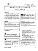
5. Burner lights but gas valve turns off after TFI
Weak flame, flame not in contact with the spark electrode of
flame sensor. Check that flame sensor tip is in the flame.
For proper sensing, the rod tip must be 3/8” (10mm) to 1/2”
(13mm) in the flame. See figure 1.
Dirty or corroded flame sensor
Faulty flame sensor wiring
Poor burner ground
Note: For more information on BASO ignitions and other products, plus
complete installation instructions, please visit us at www.baso.com.
Figure 1: Proper Flame Sensor Position
CORRECT
FLAME TOO LOW
FLAME TOO HIGH

24 VAC Universal Intermittent Pilot Gas Ignition Control
©2018 BASO Gas Products 8
Part No. BASO-INS-C610UQRG, Rev. C www.baso.com
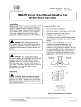
FLAME CURRENT MEASUREMENT
Flame current of the device can be measured using a standard
microammeter by simply touching the meter leads to the 2 PIN labeled FC,
as shown in Figure 2.
Flame current must be measured with pilot valve lit but no
main gas flowing.
Set meter to DC μAmp scale.
Make sure meter leads are positioned correctly [+/-].
Typical Pilot Only Flame Sense Current of 0.4 to 1.0 μAmp DC.
Figure 2: Microammeter Connection
Important: Preventative maintenance programs are an important part of maintaining
optimum and safe function of you BASO Products. For more maintenance information,
refer to the "Setup and Adjustements" sectin of the complete installation instructions. Any
attempt to repair this assembly voids the manufacturer's 2 year warranty. For a
replacement control, contact the original equipment manufacturer or nearest BASO Gas
Products distributer.
450 East Horseshoe Road
PO Box 170
Watertown, WI 53094 www.baso.com
1-877-227-6427 (1-877-BASOGAS) Published in U.S.A.
BLACK
(-)
RED (+)
/