Page is loading ...

Printed in USA Bulletin No. 608194.a
FLATCABLE FESTOON COMPONENTS
ROUNDCABLE & HOSE FESTOON COMPONENTS
3.3 (84)
4.25
(108)
1
(25)
2 (51)
dia.
0.9 (24)
3.25 (83)
2.1
(54)
0.66
(17)
max.
0.66
(17)
max.
2.3
(59)
2.1
(54) 2 (51)
dia.
0.75(19)
dia.
3.25 (83)
4.9
(124)
0.8
(21)
0.8
(21)
1.6
(41)
3
(76)
1
(25)
2.1
(54)
0.6
(16)
2 (51)
dia.
2.4
(61)
0.94
(24)
1.1
(28)
3.7 (94)
3.25 (83)
2.1 (54) 0.66
(17)
max.
Dia.
Range
“A”
3.5 (89)
3.25 (83)
B
D
Dia.
Range
“A”
TOW ARM
3.5 (89)
3.25 (83)
B
D
0.9
(24)
1.6
(41)
0.6
(16)
0.562
(14)
dia.
0.562
(14)
dia.
TOW
ARM
3.3(84)
0.94
(24)
1.1
(28)
Dia.
Range
“A”
B
D
0.75 (51)
dia.
TROLLEY
#FFT-08
Description: Fiberglass reinforced
molded nylon with
zinc plated steel cable clamp.
TOW CLAMP
#W25–FT–02
Description: Steel with zinc plating.
END CLAMP
#W25–FE–02
Description: Steel with zinc plating.
TROLLEY TOW CLAMP END CLAMP
MODEL
NUMBER
*CABLE
O.D.
“A”
in. (mm)
“B”
in.
(mm)
“D”
in.
(mm)
W25-RE-11
W25-RE-12
W25-RE-13
0.31–0.59
(7–15)
0.60–0.94
(15–24)
0.95–1.25
(24–32)
4.06
(103)
4.25
(108)
4.5
(114)
2.75
(70)
3.86
(98)
5.0
(127)
MODEL
NUMBER
*CABLE
O.D.
“A”
in. (mm)
“B”
in.
(mm)
“D”
in.
(mm)
W25-RT-11
W25-RT-12
W25-RT-13
0.31–0.59
(7–15)
0.60–0.94
(15–24)
0.95–1.25
(24–32)
1.25
(32)
1.44
(37)
1.7
(43)
2.75
(70)
3.86
(98)
5.0
(127)
MODEL
NUMBER
*CABLE
O.D.
“A”
in. (mm)
“B”
in.
(mm)
“D”
in.
(mm)
FRT–04
FRT–05
FRT–06
0.31–0.59
(7–15)
0.60–0.94
(15–24)
0.95–1.25
(24–32)
2.4
(61)
2.6
(66)
2.9
(74)
2.75
(70)
3.86
(98)
5.0
(127)
PARTS LIST
Tension Bracket #W25–BR–01
Anchor ends of wire rope and fixed end of festoon. Tow Arm #W25–TA–01
Use on moving end of festoon with Tow Clamp (above).
18 (457)
1.2
(30)
3
(76)
4 (102)
0.75
(19)
18 (457)
8 (203)
5
(127) 1.5
(38)
6 (152)
0.406(10) DIA.
(4) HOLES 0.562(14) DIA.
(4) HOLES
2.5
(64)
3
(76)
2
(51)
3
(76)
3
(76)
3
(76)
1.5
(38)
0.406 (10) dia.
(4) HOLES
Description: Steel with zinc plating. Description: Fiberglass reinforced
molded nylon with
zinc plated steel cable clamp.
Description: Steel with zinc plating.
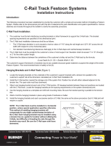
To install trolley – Place top section in
position on wire rope. Slide sections
together until they snap (lock) in place.
NOTE: Sections may be assembled in only one way. Slide “un-blocked”
end into “un-blocked” end. Do not force.
To remove – Insert small, straight bladed
screwdriver into slot beside cable opening (not slit on side
of trolley) and pry gently as shown above. Do not turn screwdriver. Slide Apart.
Figure 2
Figure 3
STEP 1– Mount tension brackets or other suitable device for
holding stretched wire rope. See Figure 3.
STEP 2– Install eye-bolts in tension brackets with end clamp on
fixed cable end of system only. See Figure 3. Eye-bolt should
protrude maximum 0.25"(6mm) through nut (Fig. 4).
STEP 3– Slide rubber bumper onto wire rope. Thread wire rope
through eye-bolt on one end of system. Install thimble in loop.
Secure wire rope with two (2) cable clamps. See Figure 3.
Repeat on other end, pulling wire rope as tight as possible before
securing.
STEP 4– Tighten wire rope by turning nuts on eye-bolts. See
Figure 4.
STEP 5–Install tow bar on crane or moving machine with slot
in tow bar facing downward. End of tow bar must be beneath
wire rope and extend beyond wire rope minimum of 2”. Affix
tow clamp to under side of tow bar. See Figure 5.
STEP 6– Lay-out trolleys on floor. Install cable or hose in trolley
hangers allowing for: 1–Three foot loop depth. 2–One additional
loop between first intermediate trolley and end clamp. 3–One
additional loop between last trolley and tow clamp. 4–Length at
each end for hook up. Tighten clamps until just snug.
STEP 7– Slide bumper to fixed cable end of wire rope. Raise
assembled festoon to wire rope and attach trolleys as shown in
Figure 1.
STEP 8– Affix cable or hose to end clamp and tow clamp and
complete hook-up. Test festoon by moving thru full Active
Travel. Adjust loop depth as required for best operation.
STEP 9–Tighten clamps to secure cable or hose.
INSTALLATION and MAINTENANCE INSTRUCTIONS
WIRE ROPE FESTOON KITS with NYLON TROLLEYS
Failure to read, understand, and follow these installation instructions may
result in damage to festoon or personal injury.
WARNING
NOTE: The traditional method of wire rope festoon installation is to assemble the entire festoon, including wire rope, on the floor
and then lift the assembly to affix both ends of the wire rope. However, because of the ease of installing these festoon trolleys onto
a stretched wire rope (see Figures 1 & 2), many users find it easier and safer to install the wire rope prior to hanging the festoon.
These instructions outline the latter method.
• TROLLEY INSTALLATION • • TROLLEY REMOVAL•
PRY GENTLY,
SLIDE APART
Pry gently.
Do not turn
screwdriver.
SLIDE/SNAP
TOGETHER
Figure 1
INSTALLATION
Figure 4
Figure 5
Wire rope mounts must be able to withstand minimum
1050 lbs.(473kg) lateral force. Improper mounts could
give way, causing damage or personal injury.
WARNING
WIRE ROPE
CLAMPS
END CLAMP
(Fixed cable end only)
NOTE:
Flat saddle shown. Round
saddle similar.
TIGHTEN THIS
NUT TO TENSION
WIRE ROPE
LOOSEN THIS NUT BEFORE
TENSIONING WIRE ROPE
TENSION BRACKET SECURELY FASTEN.
BRACKET MUST BE
ABLE TO WITHSTAND
1050 lbs. (473 kg)
LATERAL FORCE.
EYE BOLT
BUMPER
0.25" (6mm) MAXIMUM PRIOR TO
TENSIONING WIRE ROPE
THIMBLE
WIRE ROPE
TOW ARM
TOW CLAMP
HUBBELL
®
Workplace Solutions
P.O. Box 26
600 South Clark St.
Mayville, WI 53050
Phone: 920-387-5195 • Fax: 1-800-236-7335

C
LC
LC
L
System Length (SL)
Storage Distance (SD) TENSION
BRACKET
(Optional)
WIRE ROPE
RUBBER
BUMPER
TENSION
BRACKET
(Optional)
FLAT CABLE
Length per chart
plus cable needed
for hookup at
each end
WIRE ROPE
CLAMPS
&
THIMBLE
(Both Ends)
TOW
CLAMP
TOW ARM
(Optional)
INTERMEDIATE
TROLLEYS
END
CLAMP
Active Travel (AT)
MOVING
CABLE
(MC)
FIXED CABLE
END OF SYSTEM MOVING CABLE
END OF SYSTEM
Loop
Depth
(LD)
FLAT CABLE FESTOON INSTALLATION DIAGRAM
ROUND CABLE FESTOON INSTALLATION DIAGRAM
*Saddle sizes:
FR04 = 0.30" (7mm) to 0.59" (15mm) OD cable/hose.
FR05= 0.60" (15mm) to 0.94" (24mm) OD cable/hose.
C
LC
LC
L
System Length (SL)
Storage Distance (SD) Active Travel (AT)
Loop
Depth
(LD)
TENSION
BRACKET
(Optional)
TENSION
BRACKET
(Optional)
ROUND CABLE
OR HOSE
Length per chart plus
cable required for
hookup at each end
WIRE ROPE
CLAMPS
&
THIMBLE
(Both Ends)
TOW CLAMP
TOW ARM
(Optional)
INTERMEDIATE
TROLLEYS
END
CLAMP
MOVING
CABLE
(MC)
FIXED CABLE
END OF SYSTEM MOVING CABLE
END OF SYSTEM
KIT NUMBER EXPLANATION
Example: FR04 – 03
Round cable/hose festoon – Three trolleys
Size 4 saddle*
(1)KIT NUMBER EXPLANATION
Example: FF08 – 03
Flat cable festoon – Three trolleys
Legend
AT = Active Travel SL = System Length
SD = Storage Distance LD = Loop Depth
WIRE ROPE
RUBBER
BUMPER
(1) Cable/hose length listed in chart is enough for
ACTIVE TRAVEL
only, measured centerline to centerline; see diagram
above. ADD cable or hose to each end as required for hook-up to your system.
(2) Active travel, system length and minimum cable values on charts are for 30" or 48" loop depths only and are provided
as guide. Kits include necessary components for festoon system with 48" loop depth at system length shown. Vary loop depth
or cable/hose length to suit application. Shorter loop depth = shorter active travel. (1) Cable length listed in chart is enough for
ACTIVE TRAVEL
only, measured centerline to centerline; see diagram above.
ADD cable or hose to each end as required for hook-up to your system.
(2) Active travel, system length and minimum cable values on charts are for 30" or 48" loop depths only and are
provided as guide. Kits include necessary components for festoon system with 48" loop depth at system length shown. Vary
loop depth or cable length to suit application. Shorter loop depth = shorter active travel.
FLATCABLE KITS
ROUNDCABLE & HOSE KITS
ACTIVE
TRAVEL
“AT”
12' 20'
16' 27'
20' 33'
24' 40'
28' 47'
32' 54'
36' 60'
LOOP DEPTH
For planning
purposes.
(2)
30" 48"
LOOP DEPTH
For planning
purposes.
(2)
30" 48"
LOOP DEPTH
For planning
purposes.
(2)
30" 48"
FF08–02
(2 trolleys)
FF08–03
(3 trolleys)
FF08–04
(4 trolleys)
FF08–05
(5 trolleys)
FF08–06
(6 trolleys)
FF08–07
(7 trolleys)
FF08–08
(8 trolleys)
SYSTEM
LENGTH
“SL”
14' 23' 21"
25"
28"
32"
35"
39"
42"
19' 30'
23' 37'
27' 44'
32' 51'
36' 58'
40' 65'
15' 24'
20' 32'
24' 39'
29' 47'
34' 55'
39' 63'
43' 70'
(1)
MINIMUM
CABLE
REQUIRED
STORAGE
DISTANCE
“SD”
KIT
NO.
Maximum
cable size:
0.65" x 2.0"
(17 x 51mm)
MINIMUM.
May be greater
with stiff cable
or short loop.
ACTIVE
TRAVEL
“AT”
10' 18'
14' 24'
17' 30'
21' 37'
25' 43'
28' 49'
32' 55'
LOOP DEPTH
For planning
purposes.
(2)
30" 48"
LOOP DEPTH
For planning
purposes.
(2)
30" 48"
LOOP DEPTH
For planning
purposes.
(2)
30" 48"
FR04*–02
FR05*–02
FR04*–03
FR05*–03
FR04*–04
FR05*–04
FR04*–05
FR05*–05
FR04*–06
FR05*–06
FR04*–07
FR05*–07
FR04*–08
FR05*–08
SYSTEM
LENGTH
“SL”
13' 21' 21"
25"
28"
32"
35"
39"
42"
17' 27'
21' 34'
25' 40'
28' 47'
32' 53'
36' 60'
16' 25'
22' 34'
27' 42'
32' 50'
38' 58'
43' 67'
48' 75'
(1)
MINIMUM
CABLE/HOSE
REQUIRED
STORAGE
DISTANCE
“SD”
KIT
NO.
Refer to note
below*for
saddle sizes.
MINIMUM.
May be greater
with stiff cable
or short loop.

C
LC
LC
L
System Length (SL)
Storage Distance (SD) TENSION
BRACKET
(Optional)
WIRE ROPE
RUBBER
BUMPER
TENSION
BRACKET
(Optional)
FLAT CABLE
Length per chart
plus cable needed
for hookup at
each end
WIRE ROPE
CLAMPS
&
THIMBLE
(Both Ends)
TOW
CLAMP
TOW ARM
(Optional)
INTERMEDIATE
TROLLEYS
END
CLAMP
Active Travel (AT)
MOVING
CABLE
(MC)
FIXED CABLE
END OF SYSTEM MOVING CABLE
END OF SYSTEM
Loop
Depth
(LD)
FLAT CABLE FESTOON INSTALLATION DIAGRAM
ROUND CABLE FESTOON INSTALLATION DIAGRAM
*Saddle sizes:
FR04 = 0.30" (7mm) to 0.59" (15mm) OD cable/hose.
FR05= 0.60" (15mm) to 0.94" (24mm) OD cable/hose.
C
LC
LC
L
System Length (SL)
Storage Distance (SD) Active Travel (AT)
Loop
Depth
(LD)
TENSION
BRACKET
(Optional)
TENSION
BRACKET
(Optional)
ROUND CABLE
OR HOSE
Length per chart plus
cable required for
hookup at each end
WIRE ROPE
CLAMPS
&
THIMBLE
(Both Ends)
TOW CLAMP
TOW ARM
(Optional)
INTERMEDIATE
TROLLEYS
END
CLAMP
MOVING
CABLE
(MC)
FIXED CABLE
END OF SYSTEM MOVING CABLE
END OF SYSTEM
KIT NUMBER EXPLANATION
Example: FR04 – 03
Round cable/hose festoon – Three trolleys
Size 4 saddle*
(1)KIT NUMBER EXPLANATION
Example: FF08 – 03
Flat cable festoon – Three trolleys
Legend
AT = Active Travel SL = System Length
SD = Storage Distance LD = Loop Depth
WIRE ROPE
RUBBER
BUMPER
(1) Cable/hose length listed in chart is enough for
ACTIVE TRAVEL
only, measured centerline to centerline; see diagram
above. ADD cable or hose to each end as required for hook-up to your system.
(2) Active travel, system length and minimum cable values on charts are for 30" or 48" loop depths only and are provided
as guide. Kits include necessary components for festoon system with 48" loop depth at system length shown. Vary loop depth
or cable/hose length to suit application. Shorter loop depth = shorter active travel. (1) Cable length listed in chart is enough for
ACTIVE TRAVEL
only, measured centerline to centerline; see diagram above.
ADD cable or hose to each end as required for hook-up to your system.
(2) Active travel, system length and minimum cable values on charts are for 30" or 48" loop depths only and are
provided as guide. Kits include necessary components for festoon system with 48" loop depth at system length shown. Vary
loop depth or cable length to suit application. Shorter loop depth = shorter active travel.
FLATCABLE KITS
ROUNDCABLE & HOSE KITS
ACTIVE
TRAVEL
“AT”
12' 20'
16' 27'
20' 33'
24' 40'
28' 47'
32' 54'
36' 60'
LOOP DEPTH
For planning
purposes.
(2)
30" 48"
LOOP DEPTH
For planning
purposes.
(2)
30" 48"
LOOP DEPTH
For planning
purposes.
(2)
30" 48"
FF08–02
(2 trolleys)
FF08–03
(3 trolleys)
FF08–04
(4 trolleys)
FF08–05
(5 trolleys)
FF08–06
(6 trolleys)
FF08–07
(7 trolleys)
FF08–08
(8 trolleys)
SYSTEM
LENGTH
“SL”
14' 23' 21"
25"
28"
32"
35"
39"
42"
19' 30'
23' 37'
27' 44'
32' 51'
36' 58'
40' 65'
15' 24'
20' 32'
24' 39'
29' 47'
34' 55'
39' 63'
43' 70'
(1)
MINIMUM
CABLE
REQUIRED
STORAGE
DISTANCE
“SD”
KIT
NO.
Maximum
cable size:
0.65" x 2.0"
(17 x 51mm)
MINIMUM.
May be greater
with stiff cable
or short loop.
ACTIVE
TRAVEL
“AT”
10' 18'
14' 24'
17' 30'
21' 37'
25' 43'
28' 49'
32' 55'
LOOP DEPTH
For planning
purposes.
(2)
30" 48"
LOOP DEPTH
For planning
purposes.
(2)
30" 48"
LOOP DEPTH
For planning
purposes.
(2)
30" 48"
FR04*–02
FR05*–02
FR04*–03
FR05*–03
FR04*–04
FR05*–04
FR04*–05
FR05*–05
FR04*–06
FR05*–06
FR04*–07
FR05*–07
FR04*–08
FR05*–08
SYSTEM
LENGTH
“SL”
13' 21' 21"
25"
28"
32"
35"
39"
42"
17' 27'
21' 34'
25' 40'
28' 47'
32' 53'
36' 60'
16' 25'
22' 34'
27' 42'
32' 50'
38' 58'
43' 67'
48' 75'
(1)
MINIMUM
CABLE/HOSE
REQUIRED
STORAGE
DISTANCE
“SD”
KIT
NO.
Refer to note
below*for
saddle sizes.
MINIMUM.
May be greater
with stiff cable
or short loop.

Printed in USA Bulletin No. 608194.a
FLATCABLE FESTOON COMPONENTS
ROUNDCABLE & HOSE FESTOON COMPONENTS
3.3 (84)
4.25
(108)
1
(25)
2 (51)
dia.
0.9 (24)
3.25 (83)
2.1
(54)
0.66
(17)
max.
0.66
(17)
max.
2.3
(59)
2.1
(54) 2 (51)
dia.
0.75(19)
dia.
3.25 (83)
4.9
(124)
0.8
(21)
0.8
(21)
1.6
(41)
3
(76)
1
(25)
2.1
(54)
0.6
(16)
2 (51)
dia.
2.4
(61)
0.94
(24)
1.1
(28)
3.7 (94)
3.25 (83)
2.1 (54) 0.66
(17)
max.
Dia.
Range
“A”
3.5 (89)
3.25 (83)
B
D
Dia.
Range
“A”
TOW ARM
3.5 (89)
3.25 (83)
B
D
0.9
(24)
1.6
(41)
0.6
(16)
0.562
(14)
dia.
0.562
(14)
dia.
TOW
ARM
3.3(84)
0.94
(24)
1.1
(28)
Dia.
Range
“A”
B
D
0.75 (51)
dia.
TROLLEY
#FFT-08
Description: Fiberglass reinforced
molded nylon with
zinc plated steel cable clamp.
TOW CLAMP
#W25–FT–02
Description: Steel with zinc plating.
END CLAMP
#W25–FE–02
Description: Steel with zinc plating.
TROLLEY TOW CLAMP END CLAMP
MODEL
NUMBER
*CABLE
O.D.
“A”
in. (mm)
“B”
in.
(mm)
“D”
in.
(mm)
W25-RE-11
W25-RE-12
W25-RE-13
0.31–0.59
(7–15)
0.60–0.94
(15–24)
0.95–1.25
(24–32)
4.06
(103)
4.25
(108)
4.5
(114)
2.75
(70)
3.86
(98)
5.0
(127)
MODEL
NUMBER
*CABLE
O.D.
“A”
in. (mm)
“B”
in.
(mm)
“D”
in.
(mm)
W25-RT-11
W25-RT-12
W25-RT-13
0.31–0.59
(7–15)
0.60–0.94
(15–24)
0.95–1.25
(24–32)
1.25
(32)
1.44
(37)
1.7
(43)
2.75
(70)
3.86
(98)
5.0
(127)
MODEL
NUMBER
*CABLE
O.D.
“A”
in. (mm)
“B”
in.
(mm)
“D”
in.
(mm)
FRT–04
FRT–05
FRT–06
0.31–0.59
(7–15)
0.60–0.94
(15–24)
0.95–1.25
(24–32)
2.4
(61)
2.6
(66)
2.9
(74)
2.75
(70)
3.86
(98)
5.0
(127)
PARTS LIST
Tension Bracket #W25–BR–01
Anchor ends of wire rope and fixed end of festoon. Tow Arm #W25–TA–01
Use on moving end of festoon with Tow Clamp (above).
18 (457)
1.2
(30)
3
(76)
4 (102)
0.75
(19)
18 (457)
8 (203)
5
(127) 1.5
(38)
6 (152)
0.406(10) DIA.
(4) HOLES 0.562(14) DIA.
(4) HOLES
2.5
(64)
3
(76)
2
(51)
3
(76)
3
(76)
3
(76)
1.5
(38)
0.406 (10) dia.
(4) HOLES
Description: Steel with zinc plating. Description: Fiberglass reinforced
molded nylon with
zinc plated steel cable clamp.
Description: Steel with zinc plating.
To install trolley – Place top section in
position on wire rope. Slide sections
together until they snap (lock) in place.
NOTE: Sections may be assembled in only one way. Slide “un-blocked”
end into “un-blocked” end. Do not force.
To remove – Insert small, straight bladed
screwdriver into slot beside cable opening (not slit on side
of trolley) and pry gently as shown above. Do not turn screwdriver. Slide Apart.
Figure 2
Figure 3
STEP 1– Mount tension brackets or other suitable device for
holding stretched wire rope. See Figure 3.
STEP 2– Install eye-bolts in tension brackets with end clamp on
fixed cable end of system only. See Figure 3. Eye-bolt should
protrude maximum 0.25"(6mm) through nut (Fig. 4).
STEP 3– Slide rubber bumper onto wire rope. Thread wire rope
through eye-bolt on one end of system. Install thimble in loop.
Secure wire rope with two (2) cable clamps. See Figure 3.
Repeat on other end, pulling wire rope as tight as possible before
securing.
STEP 4– Tighten wire rope by turning nuts on eye-bolts. See
Figure 4.
STEP 5–Install tow bar on crane or moving machine with slot
in tow bar facing downward. End of tow bar must be beneath
wire rope and extend beyond wire rope minimum of 2”. Affix
tow clamp to under side of tow bar. See Figure 5.
STEP 6– Lay-out trolleys on floor. Install cable or hose in trolley
hangers allowing for: 1–Three foot loop depth. 2–One additional
loop between first intermediate trolley and end clamp. 3–One
additional loop between last trolley and tow clamp. 4–Length at
each end for hook up. Tighten clamps until just snug.
STEP 7– Slide bumper to fixed cable end of wire rope. Raise
assembled festoon to wire rope and attach trolleys as shown in
Figure 1.
STEP 8– Affix cable or hose to end clamp and tow clamp and
complete hook-up. Test festoon by moving thru full Active
Travel. Adjust loop depth as required for best operation.
STEP 9–Tighten clamps to secure cable or hose.
INSTALLATION and MAINTENANCE INSTRUCTIONS
WIRE ROPE FESTOON KITS with NYLON TROLLEYS
Failure to read, understand, and follow these installation instructions may
result in damage to festoon or personal injury.
WARNING
NOTE: The traditional method of wire rope festoon installation is to assemble the entire festoon, including wire rope, on the floor
and then lift the assembly to affix both ends of the wire rope. However, because of the ease of installing these festoon trolleys onto
a stretched wire rope (see Figures 1 & 2), many users find it easier and safer to install the wire rope prior to hanging the festoon.
These instructions outline the latter method.
• TROLLEY INSTALLATION • • TROLLEY REMOVAL•
PRY GENTLY,
SLIDE APART
Pry gently.
Do not turn
screwdriver.
SLIDE/SNAP
TOGETHER
Figure 1
INSTALLATION
Figure 4
Figure 5
Wire rope mounts must be able to withstand minimum
1050 lbs.(473kg) lateral force. Improper mounts could
give way, causing damage or personal injury.
WARNING
WIRE ROPE
CLAMPS
END CLAMP
(Fixed cable end only)
NOTE:
Flat saddle shown. Round
saddle similar.
TIGHTEN THIS
NUT TO TENSION
WIRE ROPE
LOOSEN THIS NUT BEFORE
TENSIONING WIRE ROPE
TENSION BRACKET SECURELY FASTEN.
BRACKET MUST BE
ABLE TO WITHSTAND
1050 lbs. (473 kg)
LATERAL FORCE.
EYE BOLT
BUMPER
0.25" (6mm) MAXIMUM PRIOR TO
TENSIONING WIRE ROPE
THIMBLE
WIRE ROPE
TOW ARM
TOW CLAMP
HUBBELL
®
Workplace Solutions
600 South Clark St.
Mayville, WI 53050
Phone: 920-387-4120
FAX: 920-387-4189
/