Page is loading ...


Operating Instructions
IMPORTANT:
Read these instructions carefully before operating the locomotive.
The following items are required for running this engine and are not
included with the model.
Fuel Butane gas. See 'Filling the gas tank'
Water See 'Filling the boiler'
Lubricating oil See 'Lubrication'
SAFETY PRECAUTIONS
This is a working model locomotive using steam under pressure
and highly flammable fuel. Provided it is operated with reasonable
care and attention, no problems should arise.
It is intended for use out of doors and must only be operated in a
well ventilated area.
Whilst the locomotive is in use, hot gasses are exhausted up the
chimney and excess steam frequently blows off through the safety
valve even when stationary, so operator and spectators should not
bend over the model.
As you will appreciate, this is not a toy and is therefore unsuitable
for young unsupervised children.
Follow manufacturer’s recommendations regarding the safe
storage of Butane gas canisters.
Some areas of the model will get quite hot whilst it is operating so
be aware of this and take extra care when handling or operating
the locomotive. Always have to hand either a fire extinguisher or
wet cloth when operating the model.

CONTENTS
Tool kit Page 4
Running in Page 4
Identification of parts of the locomotive Page 5
Preparations for operation Page 6
1. Filling the Gas Tank Page 6
2. Lubrication Page 7
3. Filling the Boiler Page 8
4. Lighting the Burner Page 9
Driving the locomotive Page 10
Storage between operating sessions Page 12
Trouble shooting & maintenance Page 13
Steam leaks Page 13
Gas system page 14
Boiler and Gas Tank Certificate, Pages 17 & 18
(EC Declaration Of Conformity).
Service and Parts. Page 20
3
Millie Instruction Booklet

TOOL KIT
The following items are included with your locomotive.
One small bottle of special steam oil for use in the lubricator.
One 60ml syringe with plastic tube for filling the boiler with water.
One spare gas jet.
One set of spare washers and ‘0’ rings.
One Allen key for cylinder socket cap screws.
RUNNING IN
All locomotives are test run before leaving the factory, but will
require several hours of running in, when new, to overcome initial
tightness and allow valves etc. to ‘bed in’. The locomotive will
waste a proportion of its water and steam until ‘run in’ due to
leaking slide valves, a tendency to prime more, and simply
overcoming the initial tightness of the moving parts. Take note in
the ‘Lighting the burner’ section regarding this matter.
As the model heats up and cools down each time you raise steam,
screws and nuts have a tendency to stretch and loosen a little so
you will also need to make regular checks and ‘nip up’ any that
become loose. Most are quite visible and easy to get to however if
there is any steam leaking from the valve chests on top of the
cylinder or front cylinder covers, refer to the Trouble Shooting
section.
Note: - When steam has been raised and you are ready to run, it is
advisable to connect a heavy truck or flat wagon with a weight (up
to 20lbs) for the locomotive to pull. The design of the model is such
that when the boiler is initially full of water, opening the regulator
may allow water to pass through the steam regulator. As this
reaches the superheater, the water will flash into steam causing the
locomotive to accelerate rapidly. An alternative method is to initially
run the locomotive on blocks or a ‘rolling road’.
After 5 to 10 minutes the water level in the boiler will have reduced
and the model can be run light, if desired.
When the locomotive is fully bedded in, this tendency will lessen.
4


PREPARING FOR OPERATION
The locomotive must be serviced before being operated. It is
important to perform all the following operations.
1) FILLING THE GAS TANK
The filling of the gas tank should only be carried out in a well-
ventilated area, where there are no naked lights or other lighted
locomotives close by. Ordinary Butane or Iso-butane gas (as used
in gas cigarette lighters) is the preferred fuel, though for economy,
the larger canisters as used for blowlamps or camping stoves etc.
are better. The larger canisters have an EN417 threaded self
sealing valve on top and require a special adapter to couple up to
the filler valve on the locomotive. A special brass gas filler adapter
is obtainable from your local garden railway supplier or direct from
ROUNDHOUSE.
Mixed gasses are also available and may be used if ordinary
butane or iso-butane are not available, but see the ‘Gas System’
section for more information.
Before attempting to fill the gas tank, make sure that the gas
control valve is closed by turning it clockwise and that there are no
other operating locomotives or naked flames nearby.
The filler valve for the gas tank is on top of the gas tank at the rear
of the cab. Ensure that the gas canister is fitted with a correct
adaptor then invert it and place its nozzle over the gas filler valve.
Support the locomotive from underneath in the area of the tank,
and press the canister down.
The gas will be heard hissing as it enters the tank and a small
amount will escape around the valve. This is quite normal and is
the tank venting as the liquid enters. After about 20 to 30 seconds
liquid gas will emerge from the valve showing that the tank is full.
Remove the canister immediately. Filling times will vary depending
on the temperature of the locomotive and are for guidance only.
6

2) LUBRICATION
Regular lubrication of all working parts is important and should be
carried out before each operating session. The slip eccentric valve
gear is located between the rear wheels and the frames and is
lubricated by running oil down the back of the wheels. There are
two types of lubrication required: The external moving linkages and
bearings are lubricated with a medium oil such as motor engine oil,
and the internal steam mechanisms such as cylinders, pistons and
valves are lubricated with a special steam oil that is mixed with the
steam. Infrequent external lubrication will allow parts to run dry,
and over oiling can form pools around operating parts that attract
dirt and grit. If too thin an oil is used it will evaporate very quickly as
the loco gets hot – leading to dry running. We recommend the use
of a 20-50 motor oil for external lubrication.
Internal lubrication is achieved by steam oil that is mixed with the
steam in the displacement lubricator, housed in the left-hand side
of the cab. Remove the knurled cap from the top and slacken the
drain screw two or three turns at the bottom but do not remove it.
Any water in the lubricator will run out through the drain screw.
Tighten the drain screw and refill with the steam oil supplied, then
replace the cap. Take time filling the lubricator, especially when
7

cold, as the oil takes time to run down and may trap an air bubble.
Both cap and drain screw are fitted with ‘0’ rings and need only be
closed finger tight.
NOTE: Only special steam oil as supplied should be used in the
lubricator and under no circumstances should ordinary oil be
substituted, or damage may result. The gas and steam regulators
will require periodic lubrication – see the troubleshooting section for
details.
3) FILLING THE BOILER
A syringe and plastic pipe are supplied for filling of the boiler. The
boiler is filled with water through the safety valve bush, housed on
top of the boiler. Remove the safety valve by unscrewing it using
the knurled ring at its base. Fill the boiler right to the top with clean
water. Distilled water is recommended if available. If distilled water
is unavailable, clean tap water can be used in soft water areas.
Also, rain water or water from a dehumidifier can be used provided
8

9
that it is adequately filtered Do not use deionised water as this type
of water may cause long term damage to the boiler and fittings.
There has to be a space above the water to allow steam to be
raised so, insert the end of the plastic pipe into the boiler and
withdraw 30ml of water with the syringe. Replace the safety valve
finger tight.
4) LIGHTING THE BURNER
WARNING: Before lighting read the section on gas system
troubleshooting and be aware of potential problems. If the gas
system is not operating correctly, shut it off immediately or
damage may result. Move the locomotive to another location before
lighting. Butane is heavier than air and small pockets of gas can
collect around the locomotive during filling.
To light the burner, hold a lighted match or cigarette lighter over the
top of the boiler and slowly open the gas regulator by turning it anti
-clockwise. The full range of adjustment (closed to fully open) is
achieved within the first half to three quarters of a turn of the
gas regulator knob any more is unnecessary.
The gas should ignite almost immediately with a pop as the flame
travels down the sides of the boiler and into the combustion
chamber at the bottom. The burner should be just audible but not
too loud.
NOTE as stated above, the gas regulator should be opened slowly
until the burner ignites. If opened too quickly, particularly when the
engine is cold or if the gas tank has just been filled, it is possible
that the flame may not travel down into the combustion chamber
but stay in the top of the firebox and over the boiler. If this should
happen, the blue flame will be visible around the top of the firebox.
Should this happen, turn off the gas immediately or damage may
result and then re-light it. If the problem persists, and it is not
possible to ignite the burner correctly, then refer to gas system
troubleshooting.
When full working pressure has been reached (about 40psi), the

safety valve will start to blow off steam, this can take up to 10 or 12
minutes in outdoor locations. Steam generation can be controlled
by the gas valve in the cab. If the safety valve blows off frequently
during running, then too much steam is being produced, which
wastes water and gas. Turning down the burner will decrease the
amount of steam made. Conversely, if steam pressure is not
maintained during a run, then the burner should be turned up. The
art of balancing steam generation to the operational requirement by
the adjustment of the gas control valve will quickly be learned. The
gas tank has a duration of about 25 minutes, though this will vary a
little depending on gas valve setting.
DRIVING THE LOCOMOTIVE
There are two main controls, both of which are housed in the cab.
1) The gas regulator, which should be used to control steam
generation as described earlier.
2) The steam regulator. This is the main steam control valve and
regulates the speed at which the engine will run. The regulator
handle is situated in the right hand cab doorway and is moved
anticlockwise to open and clockwise to close.
Select the desired direction of travel by manually moving the
locomotive for one wheel revolution in the desired direction and
crack open the regulator just a little. Initially, there will be a certain
amount of water in the pipes and cylinders which will cause the
engine to run jerkily until it is exhausted through the chimney. This
is known as priming and is quite normal and will clear after a few
moments. If the engine appears to ‘lock up’ during initial starting
from cold, it is often helpful to close the regulator and gently move
the engine manually to expel the excess water from the cylinders
then open the regulator just a little to allow a small amount of
steam through.
It is also helpful to reverse direction of the locomotive with the
regulator closed, then open the regulator just a little and run in
reverse for a short distance. This may have to be repeated until all
water clears but avoid forcing or jerking the engine as this will only
aggravate the matter. Gently does it and small regulator openings
10

will ensure the quickest results.
Once the parts have warmed up, the engine will move off steadily
and its speed can be controlled with the regulator. Subsequent
starts will be quite smooth once the cylinders etc. have reached
their normal operating temperature and the water level in the boiler
has dropped a little. This tendency to prime will often reduce as the
loco becomes ‘run in’.
To reverse the locomotive, close the regulator to bring it to a halt,
move the engine manually for one wheel revolution in the desired
direction and open the regulator again. Take care when holding the
engine to reverse it as it will be very hot in places. The area round
the rear bunker and front coupling will be OK.
The art of fine control will soon be learnt with a little practice.
Once the gas has all been used, the burner will go out and steam
pressure will drop until it is so low that the loco will no longer run.
When this happens, close both the steam and gas regulators and
allow the loco to cool down before preparing for another run. Once
it is cool enough to remove the safety valve, refill water, gas and
lubricator as previously described ready for the next run.
After the locomotive has performed a few hours of running (this will
vary from engine to engine and could typically be 8 or 10 hours)
and is wasting less steam and water, it is possible to alter the
technique to get a longer run from the loco. Turn off the gas to
extinguish the burner flame as soon as full pressure has been
reached then refill the gas tank and light the burner as previously
described. Ensure that the gas burner has been extinguished by
blowing down the side of the boiler, avoiding any steam emitting
from the safety valve. Refilling will only take about half a minute so
pressure should not drop more than a few psi. and will soon be
ready for running with a full tank of gas.
The boiler should not be allowed to run dry, but as the gas is
designed to run out before the water, this should not happen under
11

normal running conditions and if the engine is sufficiently ‘run in‘.
Monitor the locomotive closely, for the first few times you attempt
this longer run technique, and if the water runs out before the gas,
turn it off immediately. Revert to the original method of using only
one fill of gas per steaming for a few runs before trying again.
Remember, leaving the burner lit under an empty boiler can
cause damage.
For those who would like longer runs, a set of parts is available
from ROUNDHOUSE to add a water level gauge and water filling
system. This allows the boiler to be topped up at any time and
maintain a fairly constant water level. The gas tank will still require
refilling each time it is empty.
STORAGE BETWEEN OPERATING SESSIONS
At the end of an operating session, it is good practice to clean the
locomotive carefully with a clean soft cloth, and to oil all bright
metal parts.
Do not leave fuel or water in the tank or boiler for long
periods.
Do not store in places where the temperature may drop below
freezing as water may still be present in the pipework.
Ensure all controls are closed.
Periodically it may be necessary to wash off all traces of dirt and
old oil from the moving parts with paraffin (not thinners). This will
remove any accumulations of dirt or grit. After washing with
paraffin, leave to dry thoroughly overnight before re-oiling. It is
most important that clean oil is applied and allowed to penetrate
fully into all moving parts before the locomotive is run again.
Manually moving the locomotive back and forth will assist in
distributing the oil fully.
Under normal operating conditions this procedure should not be
required more than once or twice per year.
12

TROUBLE SHOOTING & MAINTENANCE
On a working model of this nature, it is important to keep all
working parts well lubricated. With constant heating up, cooling
down and the stresses of hard work, screws etc. can work loose
particularly over the first few hours of running. It is good practice to
check all fixings and cylinder screws regularly but remember, never
over tighten.
STEAM LEAKS
The cylinders are fitted with '0' rings in the glands sealing both
piston and valve rods. These can be adjusted with a spanner if
steam leaks develop. They should only be tightened just enough to
stop the leak, as over tightening will affect the running of the model.
Steam leaking from the front or rear cylinder covers can be cured
by carefully tightening the four screws that hold each one to the
cylinder block. These covers are fitted with gaskets. For the front
screws, you will need to remove the front buffer beam which is held
on by two brass cheese head screws through its front face.
Should you need to tighten the valve chest screws, these are
hidden under the front footplate and require the removal of the
body as follows.
Remove the brass screw holding the front of the smoke box down
to the footplate and lift off the smoke box after pulling it forward a
little at the bottom.
The main body will now clip off by sliding it forward a little so that
the two chassis lugs that hold down the rear of the front footplate,
and the two tabs inside the cab that clip the side tanks to the front
face of rear footplate, disengage.
Holding the body in the cab area, spring it apart slightly at the
bottom just in front of the rear footplate. It will now slide forward a
little more and can now be lifted off clear of the boiler and exhaust
pipes. You will now see the four countersunk screws holding each
valve chest in place. The valve chests are sealed with ‘O’ rings and
tightening the screws (but be careful not to over tighten) will stop
13

any leaks. Replace the main body over the boiler and exhaust
pipes. With the front footplate central on the chassis, spring out the
bottom of the side tanks a little and slide it back a little so that two
tabs in the bottom of the cab sit just in front of the slots on the rear
footplate. Slide the whole unit back ensuring that these tabs and
the two chassis lugs that hold the front footplate, line up with and
enter their respective slots. Place the smoke box over the front of
the boiler ensuring that the exhaust pipes pass up the chimney,
and clip the two retaining tabs on the rear into the slot at either
side. Replace the single screw in front of the smoke box.
GAS SYSTEM
This locomotive is fitted with our 'FX' type gas burner which is set
up and fully tested at the factory. This system is designed for use
with Butane or Iso-Butane gas. Mixed gasses, i.e. Butane with a
proportion of Propane mixed in, are available, and may be used if
straight Butane is unavailable. These come in a variety of mixes
ranging from 90/10 to 60/40 with one of the most common being
70/30. The figures refer to the proportions of the mix i.e. 70/30
contains 70% butane and 30% propane. If using mixed gasses,
always choose the one with the largest proportion of butane. The
addition of propane slightly alters the gasses properties. This can
make the burner a little more difficult to light when cold or after
filling the gas tank. Always open the regulator very slowly when
lighting, and only just sufficient for ignition to take place. Opening
too much too soon may extinguish the flame until the burner
reaches normal operating temperature.
There are two items that can affect its operation and should be
checked if it does not ignite or burn correctly.
Firstly, the fire box is designed to allow just the right amount of air
to enter, flow through the combustion chamber and exit at the top.
If the gap between the boiler and the fire box top flaps is not correct
then this will upset the balance. Too small and the flame will not
pop back into the combustion chamber, too big and much of the
heat will simply exit without doing any work. This gap is set at the
factory but should be checked if the burner becomes difficult to light
14

15
and blue flames can be seen around the top of the fire box. It
should be set so that there is a gap on both sides of 2 to 2.5 mm
between the boiler and the top edge of the flap.
Secondly, the tiny jet in these units can become blocked by small
particles of dirt making the burner difficult to light, burn weakly at
normal operating temperatures*, burn in the top of the firebox or fail
completely. If any of these should happen, clean out the jet as
follows. (* On very cold days, a burner may start off burning weakly
due to the temperature of the gas but should increase to its normal
level as the engine warms up. This is quite normal).
Carefully, disconnect the gas pipe from the gas jet holder at the
banjo connection below the frames, using a 2BA spanner. Place
the two sealing washers in a safe place. Note when connecting or
disconnecting the gas pipe and jet block, do not use excessive
force.
Slacken the screw retaining the gas jet holder and slide it out to the
rear. This operation may be made a little easier by first removing
the rear buffer beam which is fastened by two brass cheese head
screws.
Remove the jet from the gas jet holder using a 4BA spanner. Wash
out the jet in fast evaporating thinner (Cellulose or similar). Blow
through the jet from the front, which should clear most blockages.
Although the hole through the jet is tiny, if you hold it up to the light
you should be able to see quite clearly if it is blocked or not. If in
doubt, fit a new jet. A spare gas jet is included with the toolkit. Do
not use wire to clean the jet as this can damage the precision hole
and may upset the delicate balance of the gas system.
Reassemble in the reverse order, putting a small amount of PTFE
tape or plumbers sealing compound round the threads of the jet.
Ensure all connections are tight. When re-positioning the gas jet
holder in the burner, ensure that it is pushed in as far as it will go.
When re-connecting the banjo union, ensure that the two washers
are correctly fitted as in the diagram.

16
The gas regulator has a spindle ‘O’ ring housed inside the body
which may need lubrication from time to time if the control becomes
‘spongy’ in operation, making precise gas control difficult. As stated
in the lighting instructions, the full range of adjustment (closed to
fully open) is achieved within the first half to three quarters of a
turn of the gas regulator knob, and it should only be unscrewed
more than this for maintenance purposes and when the tank is
empty, and there are no naked lights nearby.
To lubricate it, remove the knurled knob which is retained by a M3
socket grub screw (M1.5 AF Allen key required) in the side.
Beneath the knob is a back-lash spring which will slide off the
spindle. Unscrew the hexagon retaining nut then screw the spindle
out of the body. The ‘O’ ring can now be lubricated.
Replace the spindle followed by the retaining nut. Slide the
backlash spring over the spindle and replace the knob. Note that
the grub screw that holds the knob in place tightens into a groove
near the end of the spindle.
Gas Regulator (Internal Parts)
Regulator
Body
Back-Lash
Spring
Regulator
Spindle
White PTFE
Washer
Knurled
Knob
‘O’ ring to be
lubricated
Hexagon
Retaining
Nut

Signed
R. Loxley (director)
Description and specification of equipment covered
Serial No.:
Desc
EC
ROUNDHOUS
E
ENGINEERI
NG CO.
LTD.
Dated
Vessel
for
Group 1
gasses
and asso-
ciated pipe
work and
fittings.
Model: Type ‘K’ gas tank Serial No.:
Test date:
Stea
m
Ge
ner
ator
and
as-
socia
Model: Type 3 boiler
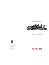
Model: MILLIE
17
Ser
Test date:

Please refer to the ‘owner’s handbook’ for your particular model of
locomotive, for details on correct use of these pressure vessels.
Pressure vessel care and maintenance
Gas tank
The gas tank is used for the storage of LPG (liquefied petroleum gas) in
the form of butane, iso-butane or as set out in the ‘owners handbook’.
The tank is fitted with a self-venting filler valve which contains no
serviceable parts. Should the filler valve become defective in any way, it
must be replaced with a new item.
It is recommended that the gas tank should undergo the following checks,
carried out by a ‘competent person’, club, society or pressure vessel
manufacturer, every year:-
1/ thorough visual inspection.
And every five to ten years:-
1/ hydrostatic pressure test to not less than 1.5 and not more than 2
times the maximum working pressure.
Boiler
The boiler is fitted with a safety valve to prevent the steam pressure rising
above the maximum allowable working pressure. This is pre-set to open
at between 2.38 bar (35 psi) and 2.72 bar (40 psi) and must not be
adjusted to increase this value.
If the safety valve becomes defective in any way, it should be replaced or
returned to the factory for service and calibration.
It is recommended that the boiler should undergo the following checks,
carried out by a ‘competent person’, club, society, or pressure vessel
manufacturer, every one to two years:-
1/ thorough visual inspection.
2/ hydrostatic pressure test to not less than 1.5 and not more than 2
times the maximum working pressure.
3/ steam test to check the correct functioning of all steam controls,
gauge and safety valve.
18


SERVICE AND PARTS
If any problems arise with this model which are not covered in
these operating instructions or, spare parts are required, owners
should first contact their local dealer. Your ROUNDHOUSE dealer is;
If your dealer is unable to help, you may contact the Factory directly:
ROUNDHOUSE ENGINEERING CO. LTD.
Units 6-10 Churchill Business Park. Churchill Road.
Wheatley. Doncaster. DN1 2TF. England
Telephone 01302 328035 Fax 01302 761312
e-mail: support@roundhouse-eng.com
www.roundhouse-eng.com
ONLINE
Millie Bertie Sammie
The Roundhouse ‘Basic Series’ family.
/