Page is loading ...

ACCUCRAFT COMPANY
33268 Central Avenue
Union City, CA 94587
Tel: 510-324-3399
Fax: 510-324-3366
Email: [email protected]
Copyright 2009
Instruction Manual
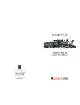
SOUTHERN PACIFIC
2-10-2 F4/F5
LIVE STEAM- BUTANE FIRED

Instruction Manual SP 2-10-2 F4/F5
Prototype Information
The Southern Pacific 2-10-2’s were general purpose locomotives and were
used system wide. The stand out news story about this class of SP loco was
that in 1922 twenty 2-10-2’s were shipped from Baldwin in one train across the
country and that train was called the Prosperity Special.
The F4 and F5 class had 63 inch drivers, 29”x32” cylinders, weighted 397,900
lbs. and had a boiler pressure of 200 lbs.
F-4 #3680 is modeled by Accucraft as it appeared in 1953 after a shopping and
had a 16,000 gal semi Vanderbilt tender added.
F-5 #3765 is modeled as it looked in 1955 with a clam shell stack and semi
Vander built tender. The #3765 was one of the last 2-10-2’s to be shopped.
Both these engines represent the Zenith of the 2-10-2 class on the Southern
Pacific. The 2-10-2’s were very popular on the SP and could go places that the
bigger Cab Forwards could not. Many of the 2-10-2’s were based on the SP’s
Shasta Division and were used as the main power on the original main line to
Oregon from California over the Siskiyou mountains.
1
Instruction Manual SP 2-10-2 F4/F5
NOTES:

Instruction Manual SP 2-10-2 F4/F5
9
SP 2-10-2 F4/F5 Supplemental Information
After running these models on various radius it was found that on our test
tracks this locomotive will negotiate 8 foot minimum radius. The manual states
10 foot minimum radius, and this should be regarded as a recommended
radius, but they will go sharper.
Instruction Manual SP 2-10-2 F4/F5
General information:
Southern Pacific 2-10-2 Live Steam
Model
Operating a model live steam loco-
motive is much different from running
an electrically powered engine. It is
a more hands-on, interactive experi-
ence.
The locomotive must be periodically
fueled, oiled and watered. As sup-
plied, the locomotive is manually con-
trolled, which means that you must
actually drive the locomotive using the
controls in the cab, just as you would
a full-size engine.
The performance of the engine is also
unlike electric locomotives. The loco-
motive should pull a dozen or more
standard-size freight cars on good,
level track. Grades and sharp curves
will diminish its capability. A good engi-
neer will learn the engine’s character-
istics and idiosyncrasies over time, to
get the best performance and longest
duration from it.
Safety:
For your safety, there are certain rules
that should be observed, as follows:
1. The safety valve has been set at
the factory to release at around 60
pounds per square inch of pressure.
Never tamper with the safety valve.
2. The butane fi ring system has been
designed to use butane only. Do not
use an other fuel. Other fuel will create
a dangerous condition, and will also
damage the locomotive!
3. Always make sure the fi re is out
before refueling the locomotive. You
need to be absolutely sure that there
is no fl ame burning around the engine
when refueling is done!
4. A steam engine gets hot, Be care-
ful.
Carrying the engine:
The locomotive and tender should al-
ways be carried separately because
of their weight. We suggest carrying
the locomotive to the track by support-
ing it underneath the wheels with both
hands, as opposed to lifting by the pi-
lot (which may not stand the stress)
and rear beam.
For general carrying, the engine can
be carried on a carrying tray with han-
dles.
2

Instruction Manual SP 2-10-2 F4/F5
3
Model Features:
This limited production model has
been handcrafted for Accucraft Trains
by BMMC, which is one of the most
respected makers of large scale brass
models. This museum quality model
features:
• Detailed boiler with fi ttings,
domes, pipes and handrails
• Operating steel drive rods,
valve gear and cross heads
• Prototypical livery and letter
ing
The following part is packaged sepa-
rately:
- 2mm hex head screwdriver
tools you will need for mainte
nance
- 1.5mm Allen Wrench
- 2mm hex screwdriver
- Flat head screwdriver
- Philips head screwdriver
Technical Specifi cations:
Scale/Gauge: 1:32, 45mm Gauge
Total Weight: 18 lbs
Length: 23 in.
Width: 4.5 in.
Height: 6.5 in.
Tender Information:
Length: 15 in.
Width: 4.25 in.
Height: 6 in.
Recommend Radius: 3M, 10ft.*
Boiler water capacity:
to top of water glass: 450ml
Tender water capacity: 600ml
Alcohol tank capacity: 500ml
*Be sure to leave at least 3” clear-
ance (measured from the inner rail) to
allow for overhang.
Caution!
This model is an accurate replica of the original locomotive. It has sharp
and moving parts. The locomotive drive rods are stainless steel with sharp
edges.
OPERATORS MUST NOT COME IN CONTACT WITH A MODEL THAT IS
BEING POWERED AT ANY TIME. UNDER NO CIRCUMSTANCES SHALL
ACCUCRAFT TRAINS BE RESPONSIBLE FOR ANY INCIDENTAL OR CON-
SEQUENTIAL DAMAGES ARISING IN REGARD TO ANY ACCUCRAFT
PRODUCT.
Instruction Manual SP 2-10-2 F4/F5
8
Please read following directions before unpacking your locomotive.
1. Remove foam around the locomotive. Slide the inner box cover to the side,
and open the inside cardboard box with a cutting knife.
2. Place taped locomotive on a fl at surface. Carefully cut the tape along the
wood board side surface. Be sure to cut both sides of the wood board. Slowly
lift the tape from the locomotive. Be very careful with small parts. Tape cannot
be re-used to re-pack the model. Use new packing tape if necessary.

Instruction Manual SP 2-10-2 F4/F5
7
With careful adjustments of this valve,
the engine will always have enough
water to keep running for long peri-
ods of time until the tender water tank
needs to be refi lled. The tender is
also equipped with the hand pump,
which needs to be used to prime the
axle pump. Only two or three strokes
are necessary to prime the pump.
Shutting Down:
To shut the engine down, simply close
the fuel valve.
After the fi re is out at the end of the run,
open the blow down valve and leave
it open. This will relieve the boiler of
what little pressure remains. Because
of the size of the engine, blowing down
could take several minutes.
After a day’s operation in the garden,
you”ll probably fi nd that your engine
has a coating of oil all over it. This
is steam-cylinder oil that has been ex-
hausted from the stack. A simple wipe
down with a dry cloth is all that’s nec-
essary to restore the engine to pristine
condition.
This is best done while the engine is
still warm. Wipe any grit and excess
oil from the wheels and running.
Instruction Manual SP 2-10-2 F4/F5
4
Lubrication:
1. Oil all external moving parts of the
engine and tender with a high grade,
lightweight machine oil like 3-in-1.
Don’t forget the wheel bearings in
the pilot and trailing trucks, as well as
those in the tender. Don’t over-oil; a
tiny drop will do the job.
2. Place the engine and tender on
the track and couple them together.
The drawbar between the units has
two holes. For tighter curves, use the
rear hole. For wide-radius curves, the
engine and tender can be coupled
more closely together, using the front
hole. Then connect the water feed, ful
and water return lines.
3. The adjustable lubricator located
in the cab ensures the cylinders and
valves are properly lubricated inside.
As the steam passes through it, a small
amount will condense into water. This
water will sink to the bottom of the
lubricator, forcing a similar quantity of
oil into the steam line and thus to the
cylinders.
Remove the lubricator cap and draw
out any water from previous run with
a syringe. Use only proper steam cyl-
inder oil. Fill the lubricator, but leave
a small air space between the oil and
the cap.
4. Fill the tender with water. Open the
throttle valve a little and pump water
into the boiler. Fill the boiler until the
water reaches the top of the glass.
This is a BIG locomotive and it will
take a lot of water. Do not overfill the
boiler; there needs to be room above
the water for steam to form.
Use only distilled water in your
engine’s boiler. Tap water contains
minerals that will leach out, cloud the
water glass, and ultimately affect per-
formance of the engine.
5. The fuel tank is located in the ten-
der beneath the oil bunker.
***Butane gas can be purchased at
the grocery store or at a tobacconist’s
as cigarette lighter refills. (Butane can
also be purchased more economically
in larger containers at camping supply
store, but these cans will require a
special adaptor for filling the engine’s
tank.) Simply press the nozzle of the
butane canister hard onto the filler
valve atop the tank, making sure that
the gas valve is closed.***

Instruction Manual SP 2-10-2 F4/F5
5
You will hear the gas transferring and
will see a little gas bleed out of the
valve. The gas may tend to sputter
a little from time to time while filling.
When the tank is full, the gas will begin
to sputter a lot and much more gas
will escape the valve. When the gas
tank is full you are ready to fire up the
engine.
NOTE: Because of the size of this
locomotive and the fact that it has two
burners, a very large gas tank has
been provide, which takes a while to
completely fill.
If you find that you are getting relatively
short runs and there is still a lot of water
left in the boiler, chances are that you
didn’t fill the gas tank all the way.
Firing up:
The engine’s burners reside at the
back of the flues inside the boiler.
Open the hinged smokebox door at
the front of the engine and you’ll be
able to see both flues.
To light up, strike a match and hold
it at the open smokebox door while
simultaneously opening the gas valve
in the tender very slowly until the
gas ignites. You should hear the gas
coming into the burner. Opening the
valve too wide or too fast may blow out
the flame or cause the fire to burn in
the smokebox.
The fire should flash back into the
back of the flues with a quiet “pop.”
If it wants to burn in the smokebox or
in the forward part of the flues, slowly
close the gas valve until it flashes back
to the burner. Don’t let the fire burn in
the smokebox your engine will not run
as it should and may be damaged.
The fire should burn in crescent-
shaped flames that should be clearly
visible through the smokebox door.
The flames should be bright blue and
should burn steadily. If they sputter or
look yellow or green, adjust the gas
valve accordingly.
The object is to run the burner at the
lowest setting possible to operate
the engine, thereby increasing the
efficiency of the engine and the
duration of the run. You’ll get the hang
of this with practice.
Make certain that both burners have
ignited by looking down the flues at the
fires. If only one burner is lit, simply
strike another match and put the flame
in the smokebox. This should ignite
the second burner. If a burner goes
out while the engine is in operation
(you might be able to tell by the sound
of the fire or by sluggish performance)
it must be manually relit. One burner
will not automatically ignite the other.
Instruction Manual SP 2-10-2 F4/F5
6
After ten or twelve minutes, pressure
on the pressure gauge should read
about 20 psi (pounds per square inch)
or so. The safety valve is set at 60
psi. When the pressure on the gauge
reaches 40 psi, the engine can be
run.
Drain Cocks:
This locomotive is fitted with working
drain cocks on the cylinders. When
first starting out, the cocks should be
open (levers moved to the “outside”
positions). This will allow water in the
cylinders to drain while the cylinders
heat up to working temperature.
As steam enters cold cylinders, it
condenses, so expect a fair amount
of water to come out at the beginning
of each run. Once cylinders have
warmed up, you can close close drain
cocks. To close them move the levers
to the “up” position.
Running:
Move the reversing lever at the right
side of the cab to the forward posi-
tion. With the engine on the track
and without a train, open the throttle.
The engine may need to be pushed a
little to overcome the steam condens-
ing into water in the cold cylinders,
but open drain cocks will minimize
this. After a few moments, the engine
should take off on its own, moving
away smoothly.
Once the engine is running smoothly,
a train can be coupled on and the run
can proceed.
Since all of the locomotive’s functions
are controlled from the cab, it can be
driven like a full-size engine, meaning
that you’ll have to stay with the engine
though the run if you want to change
speed or direction.
If you have suitable track, the engine
can be left to run on its own at a steady
speed. Keep your eye on the water
glass. With practice and good weather,
steady runs of an hour or more are not
uncommon for this engine.
Axle Pump:
This locomotive is equipped with an
axle pump and bypass valve. The
pump moves water from the tender
to a check valve on the locomotive.
The bypass valve is located on the
back right side of the cab. When the
bypass valve is completely shut, water
is pumped into the locomotive. When
the bypass valve is open, the pump
will re-circulate water back into the
tender.
/