Page is loading ...

AN18658643414602-001101 | 1
Instructions / Vejledning / Anleitung / Instructions / Instrucciones / Istruzioni / Instruktioner / Instruções / Instructies /
Ohjeet / Οδηγίες / Instruksjoner / Инструкции / Instrucţiuni / Pokyny / Instrukcje / Инструкция
OPTYMA™ Plus Condensing Units
OP-LPQM, OP-MPYM, OP-MPXM,
OP-MPGM, OP-MPBM, OP-LPOM
www.danfoss.com
Optyma™
by Danfoss
2018
Eco
Design
© Danfoss | DCS (CC) | 2019.11
English / English p. 2
Dansk / Danish p. 7
Deutsch / German p. 12
Français / French p. 17
Español / Spanish p. 22
Italiano / Italian p. 27
Svenska / Swedish p. 32
Português / Portuguese p. 37
Nederlands / Dutch p. 42
Suomi / Finnish p. 47
Eλληνικά / Greek p. 52
Norsk / Norwegian p. 57
български (Bălgarski) / Bulgarian p. 62
Română / Romanian p. 67
Čeština / Czech p. 72
Polski / Polish p. 77
Русский / Russian p. 82
GA Drawings / GA-tegninger / GA-Zeichnungen / Schémas GA / Diagramas GA / Disegni d’assieme /
GA Drawings / Desenhos GA / GA-tekeningen / GA-piirustukset / Σχεδιαγράμματα / GA-tegninger / GA
Чертежи / Diagrame AG / Výkresy / Rysunki GA / Компоновочные чертежи
p. 87
PI Diagram / PI-diagram / RI-Fließbild / Schéma de tuyauterie et d'instrumentation / Diagrama de PI /
Schema PI / PI-diagram / Diagrama PI / P&ID-schema / PI-kaavio / Διάγραμμα PI / PI-diagram / PI
диаграма/ Diagrama PI / PI Diagram / Schemat PI / Гидравлическая схема
p. 90
Wiring Diagram / El-diagram / Schaltplan / Schéma électrique / Diagrama eléctrico / Schema elettrico
/ Kopplingsschema / Diagrama de ligações / El-diagram / Kytkentäkaavio / Διάγραμμα καλωδίωσης /
Koblingsskjema / Диаграма на окабеляване / Diagramă de conexiuni / Schéma zapojení / Schemat
elektryczny / Электрическая схема
p. 93

A
B
D
E
G
C
F
IP 54
(2) R134a
R513A
(2) 23 bar
(2) 5 bar
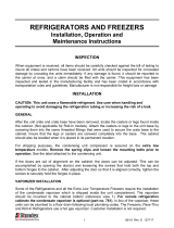
OP-MPXM034MLP00G
114X4261
Refrigerant (1) R404A R507 R448A/R449A
R407A/R407F/R452A
Voltage 230 V ~ 1N ~ 50Hz
M.W.P. HP (1) 28 bar
M.W.P. LP (1) 7 bar
Serial No. 123456CG2816
xxxxxxxxxxxxxx
LRA 60 A MCC 19 A
118UXXXXXX
MADE IN INDIA
Danfoss A/S, 6430 Nordborg, Denmark
OIL INSIDE POE 46
EAN No.
Application MBP
Optyma
™
Plus
OP-LPQM, OP-MPYM, OP-MPXM,
OP-MPGM OP-MPBM, OP-LPOM
A: Model
B: Code number
C: Application, Protection
D: Refrigerant
E: Housing Service Pressure (Maximum
working pressure)
F: Supply voltage, Locked Rotor Ampere,
Maximum Current Consumption
G: Serial Number and bar code
Name plate
Compressor running
Crankcase heater on
Fan running
Temperature value for suction pressure.
Push lower button to switch to tempera-
ture value for condensing pressure
Picture 3 : Electronic controller display
W
Q
R
X
ZY
Q: Air in R: Air out
Unit
W
[mm]
X
[mm]
Y
[mm]
Z
[mm]
Housing 1
(Code n° 114X31-- or 114X41--)
250 550 456 456
Housing 2
(Code n° 114X32-- or 114X42--)
250 650 530 530
Housing 3
(Code n° 114X33-- or 114X43--)
250 760 581 581
Housing 4
(Code n° 114X34-- or 114X44--)
250 900 700 700
Picture 1 : Minimum mounting distances
The condensing unit must only be used for
its designed purpose(s) and within its scope of
application.
Under all circumstances, the EN378 (or
other applicable local safety regulation)
requirements must be fullled.
The condensing unit is delivered under nitro-
gen gas pressure (1 bar) and hence it cannot
be connected as it is; refer to the «installation»
section for further details.
The condensing unit must be handled with cau-
tion in the vertical position (maximum oset
from the vertical : 15°)
Installation and servicing of the
condensing units by qualied
personnel only. Follow these
instructions and sound refrigeration
engineering practice relating to installation,
commissioning, maintenance and service.
2 | AN18658643414602-001101
© Danfoss | DCS (CC) | 2019.11
Picture 4 : Normal wiring Picture 5 : Temporary wiring
T: Mounting brackets for stacked mounting (not supplied)
U: M8 bolts for stacked mounting (supplied)
V: Mounting bolts (not supplied)
T
U
U
V
V
Picture 2 : Stacked mounting
Instructions

Instructions
AN18658643414602-001101 | 3
© Danfoss | DCS (CC) | 2019.11
1 – Introduction
These instructions pertain to Opty-
ma
™
Plus condensing units OP-MPYM,
OP-MPXM, OP-MPGM, OP-LPQM, OP-LPOM & OP-
MPBM used for refrigeration systems. They pro-
vide necessary information regarding safety and
proper usage of this product.
The condensing unit includes following:
• Microchannel heat exchanger
• Reciprocating or scroll compressor
• Receiver with stop valve
• Ball valves
• Sight glass
• High & low pressure switches
• Replaceable lter drier
• Electronic controller
• Main circuit breaker (Main switch with overload
protection)
• Fan and compressor capacitors
• Compressor contactor
• Robust weather proof housing
• Liquid injection controller (Module B Plus)*
• Electronic expansion valve (ETS6)*
*Only for P02 version
2 – Handling and storage
• It is recommended not to open the packaging
before the unit is at the nal place for installa-
tion.
• Handle the unit with care. The packaging al-
lows for the use of a forklift or pallet jack. Use
appropriate and safe lifting equipment..
• Store and transport the unit in an upright posi-
tion.
• Store the unit between -35°C and 50°C.
• Don’t expose the packaging to rain or corrosive
atmosphere.
• After unpacking, check that the unit is com-
plete and undamaged.
3 – Installation precautions
Never place the unit in a ammable atmos-
phere.
Place the unit in such a way that it is not bloc-
king or hindering walking areas, doors, windows
or similar.
• Ensure adequate space around the unit for air
circulation and to open doors. Refer to picture
1 for minimal values of distance to walls.
• Avoid installing the unit in locations which are
daily exposed to direct sunshine for longer pe-
riods.
• Avoid installing the unit in aggressive and dus-
ty environments.
• Ensure a foundation with horizontal surface
(less than 3° slope), strong and stable enough
to carry the entire unit weight and to eliminate
vibrations and interference.
• The unit ambient temperature may not exceed
50°C during o-cycle.
• Ensure that the power supply corresponds to
the unit characteristics (see nameplate).
• When installing units for HFC refrigerants, use
equipment specically reserved for HFC refri-
gerants which was never used for CFC or HCFC
refrigerants.
• Use clean and dehydrated refrigeration-grade
copper tubes and silver alloy brazing material.
• Use clean and dehydrated system components.
• The suction piping connected to the compres-
sor must be exible in 3 dimensions to dampen
vibrations. Furthermore piping has to be done
in such a way that oil return for the compres-
sor is ensured and the risk of liquid slug over in
compressor is eliminated.
4 – Installation
• The installation in which the condensing unit is
installed must comply to pressure Equipment
Directive (PED) 2014/68/EU. The condensing unit
itself is not a ”unit” in the scope this directive.
• It is recommended to install the unit on rubber
grommets or vibration dampers (not supplied).
• It is possible to stack units on top of each other.
Unit
Maximum
stacking
Housing 1
(Code no. 114X31-- or 114X41--)
3
Housing 2
(Code no. 114X32-- or 114X42--)
2
Housing 3
(Code no. 114X33-- or 114X43--)
2
Housing 4
(Code no. 114X34-- or 114X44--)
2
• When stacking, the topmost unit must be secu-
red to the wall, as shown in picture 2.
• Slowly release the nitrogen holding charge
through the schrader port.
• Connect the unit to the system as soon as pos-
sible to avoid oil contamination from ambient
moisture.
• Avoid material entering into the system while
cutting tubes. Never drill holes where burrs
cannot be removed.
• Braze with great care using state-of-the-art
technique and vent piping with nitrogen gas
ow.
• Connect the required safety and control de-
vices. When the schrader port is used for this,
remove the internal valve.
• It is recommended to insulate the suction pipe
up to the compressor inlet with 19 mm thick
insulation.
5 – Leak detection
Never pressurize the circuit with oxygen or dry
air. This could cause re or explosion.
• Do not use dye for leak detection.
• Perform a leak detection test on the complete
system.
• The maximum test pressure is 31*
)
bar.
• When a leak is discovered, repair the leak and
repeat the leak detection.
*
)
25 bar for OP-.......AJ.... & OP-.......FH.... models
6 – Vacuum dehydration
• Never use the compressor to evacuate the sys-
tem.
• Connect a vacuum pump to both the LP & HP
sides.
• Pull down the system under a vacuum of 500
µm Hg (0.67 mbar) absolute.
• Do not use a megohmmeter nor apply power
to the compressor while it is under vacuum as
this may cause internal damage.
7 – Electrical connections
• Switch o and isolate the main power supply.
• Ensure that power supply can not be switched
on during installation.
• All electrical components must be selected as
per local standards and unit requirements.
• Refer to wiring diagram for electrical connec-
tions details.
• Ensure that the power supply corresponds to
the unit characteristics and that the power sup-
ply is stable (nominal voltage ±10% and nomi-
nal frequency ±2,5 Hz).
• Dimension the power supply cables according
to unit data for voltage and current.
• Protect the power supply and ensure correct
earthing.
• Make the power supply according to local stan-
dards and legal requirements.
• The unit is equipped with an electronic control-
ler. Refer to Manual RS8GDxxx for details.
• P02 version models (OP-xxxxxxxxxP02E) are
equipped with Electronic circuit board (Module
B Plus). Refer to section " Module B Plus User
Guide " of this manual.
• The unit is equipped with a main switch with
overload protection. The overload protection is
factory preset but it is recommended to check
the value before taking the unit in operation.
The value for the overload protection can be
found in the wiring diagram in the front door of
the unit.
• The unit is equipped with high and low pres-
sure switches, which directly cut the power
supply to the compressor in case of activation.
Parameters for high and low pressure cut outs
are preset in the controller, adapted to the com-
pressor installed in the unit.
For units with a 3-phase scroll compressor (OP-
MPXMxxxxxxxxE), correct phase sequence for
compressor rotation direction shall be observed.
• Determine the phase sequence by using a
phase meter in order to establish the phase
orders of line phases L1, L2 and L3.
• Connect line phases L1, L2 and L3 to main swit-
ch terminals T1, T2 and T3 respectively.

Instructions
4 | AN18658643414602-001101
© Danfoss | DCS (CC) | 2019.11
8 – Filling the system
• Never start the compressor under vacuum.
Keep the compressor switched o.
• Use only the refrigerant for which the unit is
designed for.
• Fill the refrigerant in liquid phase into the
condenser or liquid receiver. Ensure a slow
charging of the system to 4 – 5 bar for R404A/
R448A/R449A/R407A/R407F/R452A and ap-
prox. 2 bar for R134a and R513A.
• The remaining charge is done until the instal-
lation has reached a level of stable nominal
condition during operation.
• Never leave the lling cylinder connected to
the circuit.
9 – Setting the electronic controller
• The unit is equipped with an electronic control-
ler which is factory programmed with parame-
ters for use with the actual unit. Refer to Manual
RS8GDxxx for details.
• By default, the electronic controller display
shows the temperature value for the suction
pressure in °C. To show the temperature value for
the condensing pressure, push the lower button
(picture 3).
The electronic controller is factory preset for R404A
or R449A or R452A or R134a depending on the mo-
del of compressor mounted and application (Refer
Annexx in Optyma Controller installation manual).
If another refrigerant is used, the refrigerant setting
must be changed. Parameter r12 must be set to 0
before (software main switch= o).
• Push the upper button for a couple of seconds.
The column with parameter codes appears.
• Push the upper or lower button to nd parame-
ter code o30.
• Push the middle button until the value for this
parameter is shown.
• Push the upper or lower button to select the new
value: 2 = R22, 3 = R134a, 36 = R513A, 17 = R507,
19 = R404A, 20 = R407C , 21 = R407A, 37 = R407F,
40 = R448A, 41 = R449A, 42 = R452A.
• Push the middle button to conrm the selected
value.
For P02 version models (OP-xxxxxxxxxP02E), if
o30 value is 19= R404A or 40=R448A or 41=R449A
in controller,
• Push the upper or lower button to nd parame-
ter code r84.
• Push the middle button until the value for this
parameter is shown as 125
• Push the upper button to select the new value:
130.
10 – Verification before commissioning
Use safety devices such as safety pressure swit-
ch and mechanical relief valve in compliance with
both generally and locally applicable regulations
and safety standards. Ensure that they are opera-
tional and properly set.
Check that the settings of high-pressure swit-
ches and relief valves don’t exceed the maximum
service pressure of any system component.
• Verify that all electrical connections are pro-
perly fastened and in compliance with local
regulations.
• When a crankcase heater is required, the unit
must be energized at least 12 hours before ini-
tial start-up and start-up after prolonged shu-
tdown for belt type crankcase heaters.
• The unit is equipped with a main switch with
overload protection. Overload protection is
preset from factory, but it is recommended to
check the value before taking the unit in ope-
ration. The overload protection value can be
found in the wiring diagram in the unit front
door.
• Check if discharge temperature sensor is rm
and has proper contact with discharge pipe.
11 – Start-up
• Never start the unit when no refrigerant is char-
ged.
• All service valves must be in the open position.
• Rotalock valve on the receiver must be tur-
ned 1 round to close direction to get the right
condensing pressure for the pressure transmit-
ter
• Check compliance between unit and power
supply.
• Check that the crankcase heater is working.
• Check that the fan can rotate freely.
• Check that the protection sheet has been re-
moved from the backside of condenser.
• Balance the HP/LP pressure.
• Energize the unit. It must start promptly. If the
compressor does not start, check wiring confor-
mity and voltage on terminals.
• Eventual reverse rotation of a 3-phase compres-
sor can be detected by following phenomena;
the compressor doesn’t build up pressure, it has
abnormally high sound level and abnormally
low power consumption. In such case, shut
down the unit immediately and connect the
phases to their proper terminals.
• If the rotation direction is correct the low pres-
sure indication on the controller (or low pres-
sure gauge) shall show a declining pressure and
the high pressure indication (or high pressure
gauge) shall show an increasing pressure.
12 – Check with running unit
• Check the fan rotation direction. Air must ow
from the condenser towards the fan.
• Check current draw and voltage.
• Check suction superheat to reduce risk of slug-
ging.
• When a sight glass is provided observe the oil
level at start and during operation to conrm
that the oil level remains visible.
• Respect the operating limits.
• Check all tubes for abnormal vibration. Move-
ments in excess of 1.5 mm require corrective
measures such as tube brackets.
• When needed, additional refrigerant in liquid
phase may be added in the low-pressure side as
far as possible from the compressor. The com-
pressor must be operating during this process.
• For P02 version models (OP-xxxxxxxxxP02E) :
- Check sight glass and make sure no bubbles in
liquid line for proper liquid injection.
- When o30 is set 19= R404A or 40=R448A or
41=R449A and readout U26 > 125 in controller,
check and make sure liquid injection is ON. Eco-
nomizer inlet pipe should be cold.
• Do not overcharge the system.
• Follow the local regulations for restoring the
refrigerant from unit.
• Never release refrigerant to atmosphere.
• Before leaving the installation site, carry out a
general installation inspection regarding clean-
liness, noise and leak detection.
• Record type and amount of refrigerant charge
as well as operating conditions as a reference
for future inspections.
13 – Emergency running without controller
In case of controller failure, the condensing unit
can still be operated when the controller stan-
dard wiring (picture 4) is modied into a tempo-
rary wiring (picture 5) as described below.
This modication may be done by authorized
electricians only. Country legislations have to be
followed.
Disconnect the condensing unit from power
supply (turn hardware main switch o)
• Contact of Room Thermostat must be possible
to switch 250VAC.
• Remove wire 22 (safety input DI3) and wire 24
(room thermostat DI1) and put them together
with an insulated 250 Vac 10mm² terminal
bridge.
• Remove wire 25 (room thermostat DI1) and
wire 11 (compressor supply) and put them
together with an insulated 250VAC 10mm² ter-
minal bridge.
• Remove wire 6 and connect it with terminal
bridge for wire 11 and 25. A fan pressure switch
or fan speed controller can be connected in
series to wire 6.
• Remove wire 14 (crankcase heater) and connect
it to the compressor contactor terminal 22.
• Remove wire 12 (supply crankcase heater),
extend this wire by using an 250 Vac 10mm²
terminal bridge and 1,0mm² brown cable and
connect it to compressor contactor terminal 21
• Remove the large terminal block from the
controller terminals 10 to 19.
• Connect the condensing unit to power supply
(turn hardware main switch on).
14 – Maintenance
Always switch o the unit at main switch be-

Instructions
AN18658643414602-001101 | 5
© Danfoss | DCS (CC) | 2019.11
fore opening the fan door (s).
Internal pressure and surface temperature
are dangerous and may cause permanent injury.
Maintenance operators and installers require
appropriate skills and tools. Tubing temperature
may exceed 100°C and can cause severe burns.
Ensure that periodic service inspections to
ensure system reliability and as required by local
regulations are performed.
To prevent system related problems, following
periodic maintenance is recommended:
• Verify that safety devices are operational and
properly set.
• Ensure that the system is leak tight.
• Check the compressor current draw.
• Conrm that the system is operating in a way
consistent with previous maintenance records
and ambient conditions.
• Check that all electrical connections are still
adequately fastened.
• Keep the unit clean and verify the absence of
rust and oxidation on the unit components,
tubes and electrical connections.
The condenser must be checked at least once a
year for clogging and be cleaned if deemed ne-
cessary. Access to the internal side of the conden-
ser takes place through the fan door. Microchan-
nel coils tend to accumulate dirt on the surface
rather than inside, which makes them easier to
clean than n-&-tube coils.
• Switch o the unit at main switch before ope-
ning the fan door.
• Remove surface dirt, leaves, bres, etc. with
a vacuum cleaner, equipped with a brush or
other soft attachment. Alternatively, blow com-
pressed air through the coil from the inside out,
and brush with a soft bristle. Do not use a wire
brush. Do not impact or scrape the coil with the
vacuum tube or air nozzle.
• Before closing the fan door, turn the fan blade
in a safe position, to avoid that the door hits the
fan.
If the refrigerant system has been opened, the
system has to be ushed with dry air or nitrogen
to remove moisture and a new lter drier has to
be installed. If evacuation of refrigerant has to be
done, it shall be done in such a way that no refrige-
rant can escape to the environment.
15 – Declaration of conformity
• Pressure Equipment Directive 2014/68/EU
EN 378-2:2016 - Refrigerating systems and Heat
Pumps - Safety and environmental requirements-
Parts 2: Design, construction, testing, marking
and documentation.
Low Voltage Directive 2014/35/EU EN 60335-
1:2012 + A11:2014- Household and similar elec-
trical appliances-Safety-Part 1: General require-
ments-for all above mentioned condensing units
Eco-design DIRECTIVE 2009/125/ EC, esta-
blishing a framework for the setting of Eco-design
requirements for energy-related products.
REGULATION (EU) 2015/1095, implementing Eco-
design Directive 2009/125/EC with regard to Eco-
design requirements for professional refrigerated
storage cabinets, blast cabinets, condensing units
and process Chiller.
• Condensing unit measurements are made accor-
ding to standard “EN 13771-2:2007” – Compressor
and condensing units for refrigeration-perfor-
mance testing and test methods- part 2: Conden-
sing units.
16 - Warranty
Always transmit the model number and serial
number with any claim led regarding this pro-
duct.
The product warranty may be void in following
cases:
• Absence of nameplate.
• External modications, in particular, drilling,
welding, broken feet and shock marks.
• Compressor opened or returned unsealed.
• Rust, water or leak detection dye inside the
compressor.
• Use of a refrigerant or lubricant not approved
by Danfoss.
• Any deviation from recommended instructions
pertaining to installation, application or main-
tenance.
• Use in mobile applications.
• Use in explosive atmospheric environment.
• No model and serial number transmitted with
the warranty claim.
17 – Disposal
Danfoss recommends that condensing
units and oil should be recycled by a sui-
table company at its site.

Instructions
6 | AN18658643414602-001101
© Danfoss | DCS (CC) | 2019.11
Module B plus is an electronic circuit board
used in P02 version models for automatic liquid
injection into compressor scrolls set using an
electronic expansion valve.
Module B Plus
LED 2
LED 1
Module B plus is covered by touch protection
cover as Picture 6.
Do not remove touch protection cover unless
required. Switch of the unit before removing this
cover.
LED2 LED1
Module B plus Inside
Picture 6
Application
Module B Plus controls liquid injection, and it also
monitors the following parameters: Discharge gas
temperature, phase sequence and phase failure.
Functional description
• Liquid injection
- Module B Plus can control discharge gas
temperature. The default set point is 125 °C, this
is required to run the condensing unit within
safe envelope.
Do not change this set point.
- When compressor stops the liquid injection
18 - Module B Plus - User guide
valve will be closed within 6 seconds.
• Discharge gas temperature overheat protection
- Discharge gas temperature sensor from Module
B Plus can detect discharge gas temperature
within the range -50 to 180°C, temperature
measurement accuracy ±0.5°C. Discharge
sensor is installed within 150mm from
compressor discharge port.
- If the discharge gas temperature is higher than
Overheat Trigger Point (set point + 10 K)within
1 second, alarm relay (J5) will open. This status
is named as DGT Overheat Static referring to
Table 1. If the discharge gas temperature lower
than Reset Point (Set Point -15 °C) continuously
for 5 minutes, the alarm relay (J5) will close. This
5 minutes delay status is named as DGT Reset
Delay.
- If the discharge gas temperature overheat
more than 5 times within 1 hour, alarm relay
(J5) locks on open status and only can be
reset by resetting Module B Plus power supply
manually (switch-o the unit and switch-on
again after some time). This status is named
as DGT Overheat Lock, refer table 1 for error
identication.
- If discharge gas temperature sensor is
malfunction, i.e. Sensor Open, Sensor Short
circuit or Out of Range, alarm relay (J5) locks
on open status too, refer table 1 for error
identication.
• Phase protection
- Phase sequence and missing phase detection
will only be performed every time the
compressor was powered on. If a wrong phase
status Phase Loss or Phase Reverse detected,
within 4.5s to 5s, alarm relay (J5) will open and
lock on open status. This lock on open status
only can be reset by resetting Module B Plus
power supply manually, refer table 1 for error
identication.
• User interface
- Module B Plus powers on, power LED 1 will
be solid red all the time. When the Module is
powered o, power LED 1 will be o. If Module
B Plus powers on and has no error, status LED 2
will be solid green on. Refer picture 6 for LED 1
and LED 2 location on module B plus.
- If Module B Plus powers on, and detects an error,
status LED 2 will be yellow and red blinking one
second alternately. Detail blink code see table 1.
Picture 7.
135
80
90
100
110
120
130
140
01020304050607
08
0
Liquid injection zone
Discharge gas temperature(°C)
Overheat Trigger Point ( Set Point +10 K)
DGT reset delay (5 min)
DGT Overheat static
(Compressor stop)
Alarm relay (J5) Close
(Compressor start)
DGT overheat lock
Set Point =125 °C
Set Point -15 K
< 60 min
• Module B plus communication with Optyma
Plus controller.
- When alarm relay (J5) is open, signal is
communicated to Optyma controller digital
input 2 (DI2), which enables safety alarm (A97)
in Optyma plus controller and power supply to
compressor will be stopped immediately.
Model B Plus wiring diagram
DI1 DI2
230Vac
L
N
PE
Supply
Optyma
Plus
Controller
084B
A1
N
X1
L1 L2 NL3
I > I > I >
2 4 6
Q
1
F1
L
N
PE
PE
L1
L2
L3
J1 J13 J2 J3 J4
J5
A3
Module B+
T>
S1
R8
M
M4
K2
M
3~
M1
P
N
P'
N'
PE
A2
3A
Table 1: Error Blink Code (LED 2 Yellow -Red Blink code)
Category
Yellow
Blink
Times
Red
Blink
Times
Error Description Action
Discharge
gas
temperature
1
1
DGT Overheat
static/ DGT
Reset Delay
Discharge gas temperature
is higher than compressor
stop trip point
Check if Optyma Controller shows safety alarm (A97). If yes, wait till it gets resolved
automatically. If this error is observed frequently, check if unit is running in recommended
envelope.
2
DGT Overheat
Lock
DGT Overheat Static occurs
5 times within 1 hour
Reset Module B Plus supply manually (switch-o the unit and switch-on again after some
time).
3
DGT out of
range
DGT is out of normal range
(-50 ... 180°C)
Check if discharge gas temperature sensor is mounted properly on discharge line. Check
discharge gas temperature on Optyma Plus controller parameter U27 (should be within -50 ...
180°C).
4
DGT Sensor
Open / DGT
Sensor Short
Discharge gas temperature
sensor open/short circuit
Check discharge temperature sensor and connection.
Triple Phase 2
1
Phase Loss One phase signal loss Check 3-Phase power supply (J2) to Module B Plus, if one of the 3 phases is missing. If yes, do
correct power supply connection and reset Module B Plus manually (switch-o the unit and
switch-on again after some time).
2
Phase Reverse Incorrect phase connection Check 3-Phase power supply (J2) to Module B Plus, if 3 phases are in correct sequence. If not,
do correct power supply connection in sequence and reset Module B Plus manually (switch-o
the unit and switch-on again after some time).

A
B
C
D
H
F
G
E
A
B
C
D
F
G
E
H
OP-LPHM018, OP-LPQM017, OP-MPYM008-009-012-014 & OP-MPHM007-010-012-015-018
H1
OP-LPQM026-048-068-074 & OP-MPBM018-024-026-034 & OP-MPXM034-046-057 & OP-MPGM033 -34 & OP-MPHM026-034 &
OP-LPHM026
H2
Instructions
AN18658643414602-001101 | 87
© Danfoss | DCS (CC) | 2019.11

A
B
C
D
F
G
E
H
OP-LPQM215-271 & OP-MPXM125-162
A
B
C
D
F
G
E
H
OP-LPQM096-136 & OP-MPXM068-080-108
English Legend
A Ø12 Hole for Mounting
B Sight Glass
C Controller Display
D Air in
E Air out
F Suction Port
G Liquid Port
H Nameplate
Electrical Cables
Note: all dimension are in mm
Dansk Legend
A Ø12-hul til montering
B Skueglas
C Regulatordisplay
D Luft ind
E Luft ud
F Sugerør
G Væskerør
H Typeskilt
Elektriske ledninger
Bemærk: Alle mål angives i mm
Deutsch Legende
A Ø12 Befestigungsbohrung
B Schauglas
C Regler-Anzeige
D Lufteinlass
E Luftauslass
F Sauganschluss
G Flüssigkeitsanschluss
H Typenschild
Elektrokabel
Hinweis: alle Maße in mm
H3
H4
Instructions
88 | AN18658643414602-001101
© Danfoss | DCS (CC) | 2019.11

English Legend
1 Compressor
2 Electric Expansion Valve
3 Micro Channel Heat Exchanger with axial fan
4 Refrigerant receiver with rotalock valve
5 Filter Drier
6 Sight Glass
7 Liqui Ball Valve
8 Suction Ball Valve
B1 Condensing Pressure Transducer (P1)
B2 Suction Pressure Transducer (P2)
B3
High Pressure cartridge Switch (auto-reset)(PSH)
B4
Low Pressure cartridge Switch (auto-reset) (PSL)
R2 Discharge Temperature Sensor (T2)
R3 Suction Temperature Sensor (T3)
R8 Discharge Temperature Sensor (T1)
Insulation
P00 Models: OP-LPQM017-026-048-068-074-096-136-215-271, OP-MPYM008-009-012-014, OP-MPBM018-024-026-034,
OP-MPXM034-046-057-68-080-108-125-162 & OP-MPGM033
P02 Models: OP-LPOM067-084-098-120-168
Instructions
90 | AN18658643414602-001101
© Danfoss | DCS (CC) | 2019.11
T3
T1
1
3
4
5
6
78
P1
P2
P2
P1
T3
T2
T1
1
3
4
5
6
78
EXV
2
B2
B2
B1
B1
R3
R3
B4
B4
B3
B3
R8
R2
R2

Code G : OP-MPXM034-046-057-068-080
DWG.NO.: 118R0192
R5: Auxiliary Temp.Sensor (optional)
R4: Auxiliary Temp.Sensor (optional)
R3: Suction Temp.Sensor
M2: Fan Motor
Q1: Main Switch
M1: Compressor
F2:
F1: Fuse (Control Circuit)
Compressor Thermal Protector
Run Capacitor (Fan)C3:
B3:
B4:
High Pressure Switch
Low Pressure Switch
B2:
B1:
Suction Pressure Tranducer
A1: Optyma Plus Controller
A2: EMI filter
F1
NL1
I >I > I >
2 4 6
Q1
COM
NC
NO
P<
B4
T>
S1
P
U
B1
P
U
B2 R1 R4
R3
R2 R5
P>
B3
DI1 DI2
+ s
230Vac 230Vac
L
N
PE
PE
out
Supply Fan
Optyma Plus Controller
N
+ s
Pc Ps S2 S3 S4 S5
S6
Display
EKA
AO1
RS485
AO2
084B8080
B-
A+
B-
A+
Modbus
s s
DI3
230Vac
Alarm Comp. FanCCH
AUX
A1
R6
M
1~
M2
C3
K2
Condensing Pressure Transducer
K2
C1
C2
K1
F2
OP-.....AJP00G
OP-.....FHP00G
P
N
P'
N'
PE
A2
WD1
M
1~
M1
3A
Code G : OP-LPQM026-048-068-074 &, OP-MPGM033-34 & OP-LPHM026, OP-MPBM018-024-026-034
K2
DWG.NO.: 118R0193
WD2
P<
B4
P>
B3
M
1~
M2
Housing 2
C3
A1: Optyma Plus Controller
C3
1~
M
M2
R6
Housing 3
COM
NC
NO
T>
S1
P
U
B1
P
U
B2 R1 R4R3R2 R5
Room Thermostat (optional)S1:
R4:
R5:
Auxiliary Temp.Sensor (optional)
Crankcase Heater
Auxiliary Temp.Sensor (optional)
R6:
DI1 DI2
+ s
230Vac 230Vac
L
N
PE
PE
out
Supply Fan
Optyma Plus Controller
N
+ s
Pc Ps S2 S3 S4 S5
S6
Display
EKA AO1
RS485
AO2
084B8080
B-
A+
B-
A+
Modbus
s s
DI3
230Vac
Alarm Comp. FanCCH AUX
A1
Suction Temp.SensorR3:
Ambient Temp.Sensor
Fan Motor
Main Switch
M2:
Q1:
R1:
Discharge Temp.Sensor (optional)
CompressorM1:
Run Capacitor (Compressor)
Run Capacitor (Fan)
Fuse (Control Circuit)F1:
C2:
C3:
Contactor :2R:2K
B4: Low Pressure Switch
B3: High Pressure Switch
B2:
B1: Condensing Pressure Transducer
Suction Pressure Tranducer
A2: EMI-filter
I > I >I >
2 4 6
Q1
NL1
M
1~
M1
C2
K2
P
N
P'
N'
PE
A2
F1
3A
Instructions
AN18658643414602-001101 | 93
© Danfoss | DCS (CC) | 2019.11

Code E : OP-LPQM048-068-074-096-136 & OP-MPXM034-046-057-068-080-108 & OP-MPBM026-034
Code E : OP-LPQM215-271 & OP-MPXM125-162
F1
I >I > I >
2 4 6
Q1
N
X1
L1 L2 NL3
Housing 2
C3
Housing 3
M
1~
M2
C3
1~
M
M2
A1: Optyma Plus Controller
DWG.NO.: 118R0194
Room Thermostat (optional)S1:
R5:
Crankcase Heater
Auxiliary Temp.Sensor (optional)
R6:
R4: Auxiliary Temp.Sensor (optional)
Ambient Temp.Sensor
Main SwitchQ1:
R1:
R2: Discharge Temp.Sensor (optional)
M2: Fan Motor
Fuse (Control Circuit)F1:
C3: Run Capacitor Fan
ContactorK2:
B4: Low Pressure Switch
B2:
B1: Condensing Pressure Transducer
Suction Pressure Tranducer
A2: EMI-filter
COM
NC
NO
P<
B4
P>
B3
R6
T>
S1
P
U
B1
P
U
B2 R1 R4R3R2 R5
DI1 DI2
+ s
230Vac 230Vac
L
N
PE
PE
out
Supply Fan
Optyma Plus Controller
N
+ s
Pc Ps S2 S3 S4 S5
S6
Display
EKA
AO1
RS485
AO2
084B8080
B-
A+
B-
A+
Modbus
s s
DI3
230Vac
Alarm Comp. FanCCH
AUX
A1
K2
WD3
K2
M
3~
M1
P
N
P'
N'
PE
A2
3A
Room Thermostat (optional)S1:
Crankcase Heater
L1 L2 L2 N
N
X1
I >I > I >
2 4 6
Q1
F1
DWG.NO.: 118R0195
WD4
Auxiliary Temp.Sensor (optional)R4:
R5: Auxiliary Temp.Sensor (optional)
R6:
Ambient Temp.SensorR1:
Main SwitchQ1:
M3: Fan Motor 2
Fan Motor 1M2:
Fuse (Control Circuit)F1:
Run Capacitor (Fan 2)C4:
Run Capacitor (Fan 1)C3:
B4: Low Pressure SwitchA1: Optyma Plus Controller
B2:
B1: Condensing Pressure Transducer
Suction Pressure Tranducer
A2: EMI-filter
M
3~
M1
K2
T>
S1
P
U
B1
P
U
B2 R1 R4R3R2 R5
K2
R6
P>
B3
P<
B4
C4
1~
M
M3
COM
NC
NO
DI1 DI2
+ s
230Vac 230Vac
L
N
PE
PE
out
Supply Fan
Optyma Plus Controller
N
+ s
Pc Ps S2 S3 S4 S5
S6
Display
EKA
AO1
RS485
AO2
084B8080
B-
A+
B-
A+
Modbus
s s
DI3
230Vac
Alarm Comp. FanCCH
AUX
A1
1~
M
M2
C3
S2
P
N
P'
N'
PE
A2
3A
Instructions
94 | AN18658643414602-001101
© Danfoss | DCS (CC) | 2019.11

Code G: OP-LPQM017 & OP-MPYM008-009-012-014
Code E: OP-LPOM067-084-098
Instructions
AN18658643414602-001101 | 95
© Danfoss | DCS (CC) | 2019.11
NL1
I >I > I >
2 4 6
Q1
COM
NC
NO
P<
B4
T>
S1
P
U
B1
P
U
B2 R1 R4
R3
R2 R5
P>
B3
DI1 DI2
+ s
230Vac 230Vac
L
N
PE
PE
out
Supply Fan
Optyma Plus Controller
N
+ s
Pc Ps S2 S3 S4 S5
S6
Display
EKA
AO1
RS485
AO2
084B8080
B-
A+
B-
A+
Modbus
s s
DI3
230Vac
Alarm Comp. FanCCH AUX
A1
R6
M
1~
M2
C3
K2
WD
5
DWG.NO.: 118R0197
K2
M
1~
M1
F2
C1
K1
R7
C2
P
N
P'
N'
PE
A2
F1
3A
COM
NC
NO
P<
B4
P>
B3
R6
P
U
B1
P
U
B2 R1 R4R3R2 R5
DI1 DI2
+ s
230Vac 230Vac
L
N
PE
PE
out
Supply Fan
Optyma Plus Controller
N
+ s
Pc Ps S2 S3 S4 S5
S6
Display
EKA
AO1
RS485
AO2
084B8080
B-
A+
B-
A+
Modbus
s s
DI3
230Vac
Alarm Comp. FanCCH
AUX
A1
K2
WD
6
DWG.NO.: 118R0181
C3
1~
M
M2
N
X1
L1 L2 NL3
I >I > I >
2 4 6
Q
1
F1
L
N
PE
PE
L1
L2
L3
J1 J13 J2 J3 J4
J5
A3
Module B+
T>
S1
R8
M
M4
K2
M
3~
M1
P
N
P'
N'
PE
A2
3A

Code E: OP-LPOM120-168
English Legend
A1 : Optyma
™
Plus Controller
A2 : EMI Filter
A3 : Liquid Injection Controller
B1,B5 : Condensing Pressure Transducer
B2 : Suction Pressure Transducer
B3 : High Pressure Switch (OFF = 31bar(g),
ON = 24bar(g))
B4 : Low Pressure Switch (OFF = -0,3bar(g),
ON = 0,5bar(g))
C1 : Start Capacitor (Compressor)
C2 : Run Capacitor (Compressor)
C3 : Run Capacitor (Fan 1)
C4 : Run Capacitor (Fan 2)
F1 : Fuse (Control Circuit)
F2,F3 : Motor protector
K1 : Start Relay
K2 : Contactor
M1 : Compressor
M2 : Fan Motor 1
M3 : Fan Motor 2
M4 : Electronic Expansion Valve
Q1 : Main Switch
R1 : Ambient Temp. Sensor
R2,R8 : Discharge Temp. Sensor
R3 : Suction Temp. Sensor
R4,R5 : Auxiliary Temp. Sensor (optional)
R6 : Crankcase Heater
R7 : NTC Resistor
S1 : Room Thermostat (optional)
S2 : Door Limit Switch
X1 : Terminal
Supply : Supply
Fan : Fan
Alarm : Alarm
Comp. : Compressor
CCH : Crankcase Heater
Aux : Auxiliary
Deutsch Legende
A1: OPTYMA
™
PLUS Regler
A2 : EMI-Filter
A3 : Flüssigkeitsinjektionsregler
B1,B5: Druckmessaufnehmer (Hochdruck)
B2: Druckmessaufnehmer (Niederdruck)
B3: Hochdruckschalter (OFF = 31bar(g), ON
= 24bar(g))
B4: Niederdruckschalter (OFF = -0,3bar(g),
ON = 0,5bar(g))
C1: Anlaufkondensator (Verdichter)
C2: Betriebskondensator (Verdichter)
C3: Betriebskondensator (Lüfter 1)
C4: Betriebskondensator (Lüfter 2)
F1: Sicherung (Steuerkreis)
F2,F3: Motorschutz
K1: Anlaufrelais
K2: Schütz
M1: Verdichter
M2: Lüftermotor 1
M3: Lüftermotor 2
M4 : Elektronisches Expansionsventil
Q1: Hauptschalter
R1: Umgebungstemp.- Fühler
R2,R8: Heißgastemp.- Fühler
R3: Saugstutzentemp.- Fühler
R4,R5: Zusatztemp.- Fühler (optional)
R6: Kurbelwannenheizung
R7 : NTC-Widerstand
S1: Raumthermostat (optional)
S2 : Türendschalter
X1: Anschlussklemme
Supply: Spannungsversorgung
Fan: Lüfter
Alarm: Alarm
Comp: Verdichter
CCH: Kurbelwannenheizung
Aux: Zusatzgeräte
Dansk Legend
A1: Optyma
™
Plus regulator
A2 : EMI-Filter
A3 : Væskeindsprøjtningsregulering
B1,B5 : Kondenseringstryktransducer
B2: Sugetryktransducer
B3: Højtrykspressostat (OFF = 31bar(g), ON
= 24bar(g))
B4: Lavtrykspressostat (OFF = -0,3bar(g), ON
= 0,5bar(g))
C1: Startkondensator (Kompressor)
C2: Driftskondensator (Kompressor)
C3: Driftskondensator (Ventilator 1)
C4: Driftskondensator (Ventilator 2)
F1: Sikring (Styrekredsløb)
F2,F3 : Motorbeskyttelse
K1: Startrelæ
K2: Kontaktor
M1: Kompressor
M2: Ventilatormotor 1
M3: Ventilatormotor 2
M4 : Elektronisk ekspansionsventil
Q1: Hovedafbryder
R1: Omg. temp. føler
R2,R8: Afgangstemp. Føler
R3: Sugetemp. Føler
R4,R5: Hjælpetemp. Sensor (ekstraudstyr)
R6: Krumtaphusvarmer
R7 : NTC-modstand
S1: Rumtermostat (ekstraudstyr)
S2 : Dørgrænsekontakt
X1: Terminal
Supply : Forsyning
Fan : Ventilator
Alarm : Alarm
Comp. : Kompressor
CCH : Krumtaphusvarmer
Aux : Hjælpeudstyr
Instructions
96 | AN18658643414602-001101
© Danfoss | DCS (CC) | 2019.11
T>
S1
P
U
B1
P
U
B2 R1 R4R3R2 R5
P>
B3
P<
B4
DI1 DI2
+ s
230Vac 230Vac
L
N
PE
PE
out
Supply Fan
Optyma Plus Controller
N
+ s
Pc Ps S2 S3 S4 S5
S6
Display
EKA
AO1
RS485
AO2
084B8080
B-
A+
B-
A+
Modbus
s s
DI3
230Vac
Alarm Comp. FanCCH
AUX
A1
C4
S2
WD7
DWG.NO.: 118R0182
Module B+
L
N
PE
PE
L1
L2
L3
J1 J13 J2 J3 J4
J5
A3
R6
C3
1~
M
M2
1~
M
M3
COM
NC
NO
K2
L1 L2 L2 N
N
X1
I >I > I >
2 4 6
Q1
F1
P
N
P'
N'
PE
A2
K2
M
3~
M1
R8
M
M4
3A

Danfoss A/S
6430 Nordborg
Denmark
100 | AN18658643414602-001101
© Danfoss | DCS (CC) | 2019.11
Danfoss can accept no responsibility for possible errors in catalogues, brochures and other printed material. Danfoss reserves the right to alter its products without notice. This
also applies to products already on order provided that such alterations can be made without subsequential changes being necessary in specications already agreed. All trade-
marks in this material are property of the respective companies. Danfoss and the Danfoss logotype are trademarks of Danfoss A/S. All rights reserved.
/