Page is loading ...

cc.danfoss.com
Optyma
TM
by Danfoss
Manual / Manual / Handbuch / Manuel / Manuel
Optyma
™
Plus
Controller installation
Dedicated for Optyma
™
Plus INVERTER & New Generation.

2 BC08728642552802-001101
Manual
English version .................................................................................................................. 6
Danish version ................................................................................................................. 12
German version ................................................................................................................ 18
French version ................................................................................................................. 24
Swedish version ............................................................................................................... 30
Controller Installation

3BC08728642552802-001101
Manual
Optyma
™
Plus condensing units are pre-parameterized, depending on the model of compressor
mounted and the type of refrigerant. Controller parameter “o30” for refrigerant is Factory Preset as per
below table and must be changed for other refrigerants (see chapter Commissioning - Quick start of
the unit / Refrigerant change).
Annex
Controller Installation
Optyma
™
Plus Verflüssigungssätze sind vorparametriert für das installierte Verdichtermodell und verwendete
Kältemittel. Der Reglerparameter „o30“ für Kältemittel ist gemäß der folgenden Tabelle werksseitig
voreingestellt und muss für andere Kältemittel geändert werden (siehe Kapitel zu Inbetriebnahme –
Schnellstart der Einheit/Kältemittelwechsel).
Anhang
Les groupes de condensation Optyma
™
Plus sont pré-paramétrés, en fonction du modèle de
compresseur
et du type de réfrigérant. Le paramètre du contrôleur “o30” pour le réfrigérant est préréglé
en usine comme indiqué ci-dessus table et doit être changé pour les autres réfrigérants
(voir le chapitre
Mise en service - Démarrage rapide de l’unité / Changement de réfrigérant).
Annexe
Optyma
™
Plus-kondenseringsaggregater er parameterafstemt på forhånd afhængigt af den monterede
kompressormodel og kølemiddeltypen. Regulatorparameter ”o30” for kølemiddel er i
fabriksindstillingen, som vist ovenfor i tabellen og skal ændres ved anvendelse af andet kølemidle (se
kapitlet Idriftsættelse – hurtig start af enheden/kølemiddelskift).
De luftkylda aggregaten Optyma Plus™ är förprogamerade beroende på monterad kompressormodell
och typ av köldmedium. Styrparametern ”o30” för kylmedel är fabriksinställd enligt ovan bord och måste
ändras för andra kylmedel (se kapitel Idriftsättning – Snabbstart av aggregatet/Byte av köldmedium).
Supplement
Bilaga

4 BC08728642552802-001101
Manual
Controller Installation
Code
(controller
parameter
o61 )*
Model* Optyma
™
Plus
New Generation
Code-no. Compressor* Refrigerant (controller parameter o30)*
settings are adjustable*
Factory
Presetting
R404A
(19)
R507
(17)
R134a
(3)
R513A
(36)
R407A
(21)
R407F
(37)
R448A
(40)
R449A
(41)
R452A
(42)
1 OP-MPHM007NFP00G 114X4101 NF7MLX R404A X X
2 OP-MPHM010SCP00G 114X4102 SC10MLX R404A X X
3 OP-MPHM012SCP00G 114X4104 SC12MLX R404A X X
4 OP-MPHM015SCP00G 114X4105 SC15MLX R404A X X
5 OP-MPHM018SCP00G 114X4109 SC18MLX R404A X X
6 OP-MPGM034GSP00G 114X4210 GS34MFX R134a X
7 OP-MPHM026GSP00G 114X4214 GS26MLX R404A X X
8 OP-MPHM034GSP00G 114X4229 GS34MLX R404A X X
20 OP-LPHM018SCP00G 114X3109 SC18CLX.2 R404A X X
21 OP-LPHM026GSP00G 114X3217 GS26CLX R404A X X
22 OP-LPQM048NTP00G 114X3225 NTZ48-5VM R452A X X X
23 OP-LPQM048NTP00E 114X3233 NTZ48-4VM R452A X X X
24 OP-LPQM068NTP00G 114X3241 NTZ68-5VM R452A X X X
25 OP-LPQM068NTP00E 114X3249 NTZ68-4VM R452A X X X
26 OP-LPQM096NTP00E 114X3357 NTZ96-4VM R452A X X X
27 OP-LPQM136NTP00E 114X3365 NTZ136-4VM R452A X X X
28 OP-MPXM034MLP00G 114X4261 MLZ015T5LP9 R449A X X X X X X X X X
29 OP-MPXM034MLP00E 114X4264 MLZ015T4LP9 R449A X X X X X X X X X
30 OP-MPXM046MLP00G 114X4281 MLZ021T5LP9 R449A X X X X X X X X X
31 OP-MPXM046MLP00E 114X4284 MLZ021T4LP9 R449A X X X X X X X X X
32 OP-MPXM068MLP00G 114X4308 MLZ030T5LC9 R449A X X X X X X X X X
33 OP-MPXM068MLP00E 114X4311 MLZ030T4LC9 R449A X X X X X X X X X
34 OP-MPXM080MLP00G 114X4321 MLZ038T5LC9 R449A X X X X X X X X X
35 OP-MPXM080MLP00E 114X4324 MLZ038T4LC9 R449A X X X X X X X X X
36 OP-MPXM108MLP00E 114X4344 MLZ048T4LC9 R449A X X X X X X X X X
37 OP-MPXM125MLP00E 114X4414 MLZ058T4LC9 R449A X X X X X X X X X
38 OP-MPXM162MLP00E 114X4434 MLZ076T4LC9 R449A X X X X X X X X X
39 OP-LPOM120LLP02E 114X3485 LLZ024T4LC9 R452A X X X X X
40 OP-LPOM168LLP02E 114X3486 LLZ034T4LC9 R452A X X X X X
41 OP-MPXM057MLP00G 114X4290 MLZ026T5LP9 R449A X X X X X X X X X
42 OP-MPXM057MLP00E 114X4293 MLZ026T4LP9 R449A X X X X X X X X X
43 OP-LPOM067LLP02E 114X3371 LLZ013T4LC9 R452A X X X X X
44 OP-LPOM084LLP02E 114X3372 LLZ015T4LC9 R452A X X X X X
45 OP-LPOM098LLP02E 114X3373 LLZ018T4LC9 R452A X X X X X
46 OP-MPBM024AJP00G 114X4200 CAJ9513Z R449A X X X X X
47
OP-MPBM026AJP00G 114X4212 CAJ4517Z R449A X X X X X
48 OP-MPBM026AJP00E 114X4213 TAJ4517Z R449A X X X X X
49 OP-MPBM034AJP00G 114X4226 CAJ4519Z R449A X X X X X
50 OP-MPBM034AJP00E 114X4227 TAJ4519Z R449A X X X X X
51 OP-LPQM026AJP00G 114X3216 CAJ2446Z R452A X X X
52 OP-MPGM033AJP00G 114X4220 CAJ4511Y R134a X X
53 OP-LPQM074FHP00G 114X3252 FH2511Z R452A X X X
54 OP-LPQM074FHP00E 114X3253 TFH2511Z R452A X X X
55 OP-MPLM028VVZP01E 114X4300 VLZ028TGNE9 R404A X X X X
55 OP-MPPM028VVZP01E 114X4302 VLZ028TGA R449A X X X X X X
56 OP-MPLM035VVZP01E 114X4315 VLZ035TGNE9 R404A X X X X
56 OP-MPPM035VVZP01E 114X4316 VLZ035TGA R449A X X X X X X
57 OP-MPLM044VVZP01E 114X4333 VLZ044TGNE9 R404A X X X X
57 OP-MPPM044VVZP01E 114X4334 VLZ044TGA R449A X X X X X X
64 OP-LPQM017MPP00G 114X3118 MPT16LA R452A X X X
65 OP-MPYM008MYP00G 114X4119 MLY80RAb R449A X X X
66 OP-MPYM009MYP00G 114X4120 MLY90RAb R449A X X X
67 OP-MPYM012MPP00G 114X4121 MPT12RA R449A X X X
68 OP-MPYM014MPP00G 114X4122 MPT14RA R449A X X X
69 OP-MPBM018AJP00G 114X4230 CAJ9510Z R449A X X X X X
Code (controller parameter o61):
Kode (regulatorparameter
o61) / Code (Reglerparameter o61) / Code (contrôleur paramètre o61) / Code (controller parameter o61)
Model
:
Model / Modell /
Modèle / Modell
Code-no. : Bestillingsnr. / Art-Nr. / Code n° / Artikelnummer
Compressor
:
Kompressor /
Verdichter / Compresseur / Kompressor
Refrigerant : Kølemiddel (regulatorparameter o30) / Kältemittel (Reglerparameter o30) / Réfrigérant (contrôleur paramètre o30) / Köldmedium
*Settings are adjustable : indstillinger er justerbare / Werte einstellbar / parameters sont réglables / Inställningarna kan justeras

5BC08728642552802-001101
Manual
BK
BL
BR
-C3
6
.
-X1
PE
.
-X1 N1
.
1
2
3
6
BN
BU
1
2
3
4
5
6
-K2
-C1
BN
33
34
43
44
PE
-X1
BU
BU
I > I > I >
135
246
-Q1
13
14
11
13
10
12
-K1
22
23
22
.
-X1
P<
-B4
15
.
-X1
P>
-B3
20
.
-X1
A1
A2
-K2
10
11
14
.
12
13
14
15
16
24
25
P>
1
2
P
U
-B1
P
U
-B2
BK
BK
BK
BK
RD
WH
-R1 -R2
-R3
-R5-R4
21
22
-K2
3,0A
-F1
PE
.
N2
.
P
N
P'
N'
PE
-A2
M
1~
-M1
M
1~
-M2
-R6
-B5*
-A1*
T>
-S1*
220-240V1N~/50Hz
L N PE
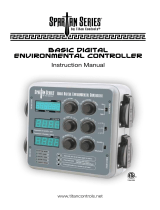
Optyma
™
Plus equipped with fixed speed compressor
N1
.
-X1
14
.
15
.
-X1
20
.
-X1
22
.
-X1
PE
.
-R7
BN
BN
PE
.
N1
.
BK
BU
BN
1~
M
GNYE
GY
GY
-M2
6
.
-R6
N2
.
N3
.
BU
BN
BU
13
14
BN
BK
GY
BU
33
34
43
44
N
.
-X1
I > I > I >
135
246
-Q1
380-400V3N~/50Hz
L1 L2 PEL3 N
PE
T1 T2 T3
M
3~
-M1
T1
T2
T3
P>
1
2
-B5*
10kOhm
3
1
2
-R8
24
25
26
27
56
57
1
2
3
6
10
11
12
14
15
16
23
22
BK
BK
BK
BK
RD
WH
-R1 -R3-R2 -R4 -R5
RD
T>
26
27
10
11
P
U
-B1
P
U
-B2
P>
-B3
P<
-B4
-A1*
-S1*
P
N
P'
N'
PE
-A2
L1 L2 L3
L1'L2' L3'
PE
PE
-A3
~
~
CDS803
L1 L2 L3
UVW
29271918 42 50 53 54696861 45
552012
6
5
4
3
2
1
PE
PE
-A4
3.0A
-F1
1
2
3
4
5
6
-K2
A1
A2
-K2
21
22
-K1
-C3
Optyma
™
Plus INVERTER equipped with variable speed compressor
Controller Installation

Controller Installation
6 BC08728642552802-001101
Manual
English Legend
A1* Controller (option)
A2 EMI filter (control circuit)
A3 EMC/RFI Filter (Compressor)
A4 Frequency Converter
B1 Condensing pressure transducer
B2 Suction pressure transducer
B3 High pressure switch
B4 Low pressure switch
B5* Fan speed controller/pressure switch (option)
C1 Start capacitor (compressor)
C3 Run capacitor (fan)
F1 Fuse (control circuit)
K1 Start Relay
K2 Contactor
M1 Compressor
M2 Fan motor
Q1 Main switch
R1 Ambient temp. sensor
R2 Discharge temp. sensor
R3 Suction temp. sensor
R4,R5 Auxiliary temp. sensor
R6 Crankcase heater
R7 Oil separator heater
R8 Potentiometer
S1* Room thermostat (option)
X Terminals
Dansk Legend
A1* Regulator (ekstraudstyr)
A2 EMIFilter (Styrekredsløb)
A3 EMC/RFI-filter (Kompressor)
A4 frekvensomformer
B1 Kondenseringstryktransducer
B2 Sugetryktransducer
B3 Højtrykspressostat
B4 Lavtrykspressostat
B5* Ventilatorhastighedsregulator/Pressostat
(ekstraudstyr)
C1 Startkondensator (Kompressor)
C3 Driftskondensator (Ventilator)
F1 Sikring (Styrekredsløb)
K1 Startrelæ
K2 Kontaktor
M1 Kompressor
M2 Ventilatormotor
Q1 Hovedafbryder
R1 Omg. temp. føler
R2 Afgangstemp. Føler
R3 Sugetemp. Føler
R4,R5 Hjælpetemp. Sensor
R6 Krumtaphusvarmer
R7 Olieudskillervarmeelement
R8 Potentiometer
S1* Rumtermostat (ekstraudstyr)
X Terminal
Deutsch Legende
A1* Regler (optional)
A2 EMV Filter (Steuerkreis)
A3 EMV Filter (Frequenzumformer)
A4 Frequenzumformer
B1 Druckmessaufnehmer (Hochdruck)
B2 Druckmessaufnehmer (Niederdruck)
B3 Hochdruckschalter
B4 Niederdruckschalter
B5* Drehzahlregler / Druckschalter (optional)
C1 Anlaufkondensator (Verdichter)
C3 Betriebskondensator (Lüfter)
F1 Sicherung (Steuerkreis)
K1 Anlaufrelais
K2 Schütz
M1 Verdichter
M2 Lüftermotor
Q1 Hauptschalter
R1 Umgebungstemp. Fühler
R2 Heißgastemp. Fühler
R3 Saugstutzentemp. Fühler
R4,R5 Zusatztemp. Fühler
R6 Kurbelwannenheizung
R7 Ölabscheiderheizung
R8 Potentiometer
S1* Raumthermostat (optional)
X Anschlussklemme
Français Légende
A1* contrôleur (en option)
A2 Filtre EMI (Circuit de commande)
A3 Filtre RFI/EMC (Compresseur)
A4 Convertisseur de fréquence
B1 transducteur de pression de condensation
B2 transducteur de pression d’aspiration
B3 pressostat haute pression
B4 pressostat basse pression
B5* Régulateur de vitesse du ventilateur/Pressostat
(en option)
C1 Condensateur de démarrage (Compresseur)
C3 Condensateur de marche (ventilateur)
F1 fusible (Circuit de commande)
K1 relais de démarrage
K2 contacteur
M1 compresseur
M2 moteur de ventilateur
Q1 sectionneur principal
R1 sonde de température ambiante
R2 sonde de température de refoulement
R3 sonde de température d’aspiration
R4,R5 sonde de température auxiliaire (en option)
R6 résistance de carter
R7 Résistance de séparateur d’huile
R8 Potentiomètre
S1* thermostat d’ambiance (en option)
X borne
Svenska Legend
A1* regulator (tillval)
A2 EMI-filter (styrkrets)
A3 EMC/RFI-filter (kompressor)
A4 Frekvensomformare
B1 Kondensortrycksgivare
B2 Högtrycksbrytare
B3 Högtrycksbrytare
B4 Lågtrycksbrytare
B5* Fläkthastighetsregulator/pressostat (tillval)
C1 Startkondensator (kompressor)
C3 Driftkondensator (fläkt)
F1 Säkring (styrkrets)
K1 Startrelä
K2 Kontaktor
M1 Kompressor
M2 Fläktmotor
Q1 Huvudbrytare
R1 Omgivningstemp. sensor
R2 Tryckrörstemp. sensor
R3 Sugtemp. sensor
R4,R5 Extra temp. sensor (tillval)
R6 Vevhusvärmare
R7 Värmare för oljeavskiljare
R8 Potentiometer
S1* Rumstermostat (tillval)
X Terminal

8 BC08728642552802-001101
Manual
Controller Installation
Commissioning .....................................................................................................................................7
Electrical installations .......................................................................................................................................................7
Main display (after controller start-up) ...................................................................................................................... 7
Parameter Menu ................................................................................................................................................................. 7
Quick start of the unit / Refrigerant change ............................................................................................................ 7
Pump Down - Function .................................................................................................................................................... 8
Day/Night - Function ........................................................................................................................................................ 8
Service and Maintenance .................................................................................................................... 8
Main Display ........................................................................................................................................................................8
Operating Parameters ...................................................................................................................................................... 8
Alarm and Error Messages .............................................................................................................................................. 9
Repair ....................................................................................................................................................9
Controller failure ................................................................................................................................................................ 9
Factory reset ......................................................................................................................................................................10
Controller Replacement of a unit on site ................................................................................................................10
Control ................................................................................................................................................10
Control of condensing pressure ................................................................................................................................. 10
Control of crankcase heater .........................................................................................................................................10
Control of Fan Speed ...................................................................................................................................................... 10
Safety Parameter “Low Pressure” ...............................................................................................................................11
Safety Parameter “High Pressure” ............................................................................................................................. 11
Contents

9BC08728642552802-001101
Manual
Controller Installation
Electrical installations
Commissioning
Main display (after controller
start-up)
Parameter Menu
Quick start of the unit /
Refrigerant change
• Arrange electrical connections as mentioned in the table below
• Remove temporarily bridge DI1 (terminals 24 - 25 of the controller) to get access to parameters and
values of the controller without starting the condensing unit
• The controller’s screen displays the Evaporation Temperature in °C
• Press short the lower button of the controller to show the Condensing Temperature in °C
• After a few seconds the display returns to the Evaporation Temperature in °C
• To get access to parameter menu press 5 seconds the upper button of the controller
• The first Parameter “r05” of the Parameter menu will be shown on the display
• Press short the upper (or lower) button to go to the next Parameter of the Parameter menu. Scroll
fast through the Parameters with a long press on these buttons
• Press short the middle button to show the value of the selected Parameter
• Press afterwards the upper (or lower) button to change the value of the selected parameter. A long
press on these buttons will change the value fast
• The value will be stored after 20 seconds without any action or with a short press on the middle
button
• After 20 seconds without pressing any button, the display returns to the main screen, the
evaporation temperature in °C. The parameter menu is closed now, to go back to the parameter
menu press again upper button 5 seconds …
• Optyma
™
Plus new generation is preset, depending on the compressor model and refrigerant type.
In the case of a “multi-refrigerant” compressor, the controller of the condensing unit is Factory
Preset as per above table (see table on page3). If this factory setting fits for the requirement of your
application, no controller parameter must be changed.
• For a refrigerant change go into the parameter menu (press upper button 5 seconds)
• Select parameter “r12” (software main switch) with a short press on lower button
• Activate parameter “r12” with middle button and change the value to 0 (zero)
• Confirm the value with a short press on the middle button (the 3 LED’s start flashing)
• Go to the parameter “o30” (Refrigerant)
• Change the value to 3 (R134a), 17 (R507), 20 (R407C), 19 (R404A), 21 (R407A), 37 (R407F), 40 (R448A),
41 (R449A), 42 (R452A), 36 (R513A)
• Confirm the value with a short press on the middle button
• Select parameter “r12” again
• Change the value to 1 (one)
• Confirm the value with a short press on the middle button (the 3 LED-signs stop flashing and the
condensing unit will start if required)
• After 20 seconds the display returns to the evaporation temperature in °C, the new refrigerant and all
relevant parameters are changed
Room Thermostat control
without Pump Down function
Pump Down control
with factory delivered low pressure transmitter
- Connect Room Thermostat to these terminals
- Connect power supply to main switch acc. wiring
diagram, located in front door inner side
- Connect power supply to main switch acc. wiring
diagram, located in front door inner side
- Increase the Setting of controller Par. c33 (Pump Down
CUT-OUT value):
e.g. Piston : 0,7bar
e.g. Scroll : 1,7bar
Note: To avoid low pressure alarm, the Setting of c33 and
r23 (for INVERTER units) should be higher than c75

10 BC08728642552802-001101
Manual
Pump Down - Function • A “pump-down” limit can be activated with the setting of parameter c33
• To avoid unwanted low pressure alarms, the setting ot this parameter should be higher than the low
pressure cut-out limit parameter c75, … e.g. below
0
Low pressure switch: Cut-In
Scroll and Recip: 0,5bar
Dierential: Parameter c76
Scroll and Recip: 0,7bar
Pump down function: Param. c33
Inverter: 2.7 bar Scroll: 1,7bar
Recip: 0,7bar
Dierential: Parameter c76
Scroll and Recip: 0,7bar
Low pressure switch: Cut-Out
Scroll and Recip: -0,3bar
Low pressure cut-out limit:
Parameter c75
Scroll: 1,4bar Recip: 0,4bar
In some areas it may be necessary to reduce noise level during night time. This is possible with the
“Day / Night” function of the Optyma
™
Plus controller which limits the fan speed for all units and the
compressor speed for INVERTER units. For activation follow the next steps …
• Activate the parameter menu (press upper button min. 5 sec.)
• Select parameter “r13” Night Offset (temperature offset related to condensing temperature setpoint
for daytime which is parameter “r29”)
• Push middle button and set the desired value, e.g. 005 for 5 Kelvin
• Confirm the value with a short press on the middle button. Do the same with the next parameters
which are required for the “Day / Night” - function …
• Select and set parameter “t17” Day start (hours), e.g. 006 for 06:00 a.m.
• Select and set parameter “t18” Night start (hours), e.g. 022 for 22:00 p.m.
• Select and set parameter “t07” Clock setting (hours), e.g. 011 for 11:xx a.m.
• Select and set parameter “t08” Clock setting (minutes), e.g. 035 for 11:35 a.m.
• Select and set parameter “t45” Clock setting (date), e.g. 010 for 10.xx.xx
• Select and set parameter “t46” Clock setting (month), e.g. 004 for 10.04.xx
• Select and set parameter “t47” Clock setting (year), e.g. 012 for 10.04.12
• All values will be stored with the middle button or after 20s without pressing any button
Day/Night - Function
• The controller displays the evaporation temperature in °C (main screen)
• It will show the readout of the condensing temperature in °C after pressing short the lower button
• Pressing short the middle button, the setpoint of the temperature difference between condensing
and ambient temperature appears which can be directly modified here by pressing the upper or
lower button.
• The display returns to main screen after a few seconds without any action on the buttons
Main Display
(Evaporating and Condensing
Temperature, Setpoint Tempera-
ture Difference)
Service and Maintenance
• Operation conditions of the condensing unit
can be displayed in the parameter menu
by selecting parameters “U” … below some
examples
u01 Condensing Pressure
u10 Status of DI1 (room thermostat)
u21 Superheat
u37 Status of DI2 (frequency converter alarm)
u52 Compressor Capacity
U22 Condensing Temperature
U23 Evaporation Pressure
U24 Evaporation Temperature
U25 Ambient Temperature
U26 Discharge Temperature
U27 Suction Temperature
U44 Voltage on A01
U56 Voltage on A02
Operating Parameters
Controller Installation

11BC08728642552802-001101
Manual
• In case of “malfunctions” 3 small LED
symbols will flash on the controller’s screen.
Acknowledge with a short press on upper
button. Here some examples below …
A2 Low Suction Pressure Alarm
A17
Safety Input Alarm (DI3: High condensing
/ low suction pressure)
A96 Discharge Gas Temperature High
A97
Digital Input Alarm (DI2: Frequency
converter alarm)
E20 Condensing Pressure Transmitter Error
E31 Ambient Temperature Sensor Error
E32 Discharge Temperature Sensor Error
E33 Suction Gas Temperature Sensor Error
E39 Evaporating Pressure Transmitter Error
Alarm and Error Messages
Repair
Fixed speed units:
See wiring diagrams on p. 4.
• Disconnect the condensing unit from power supply (turn hardware main switch off)
• Remove wire from controller terminal 22 (safety input DI3) and terminal 25 (room thermostat DI1)
and put them together
• Remove wire from controller terminal 24 (room thermostat DI1) and terminal 11 (compressor
supply) and put them together
• Remove wire 6* and connect it with terminal bridge for wire 11 and 24.
• Remove wire from terminal 14 (crankcase heater) and connect it to compressor contactor K2
terminal 22
• Remove wire from controller terminal 12 (supply crankcase heater), extend this wire
approximately 40cm and connect it to compressor contactor K2 terminal 21
• Pay attention: Remove the big terminal block from the controller or remove the complete controller
• Connect the condensing unit back to power supply (turn hardware main switch on)
Variable speed units:
See wiring diagrams on p. 5.
• Disconnect the condensing unit from power supply (turn hardware main switch off)
• Remove wire from controller terminal 22 (safety input) and terminal 6* (fan) and put them
together
• Remove wire from controller terminal 10 (compressor relay) and terminal 24 (room thermostat)
and put them together
• Remove wire from controller terminal 11 (compressor relay) and terminal 25 (room thermostat)
and put them together
• Remove wire from Inverter terminal 50 and connect to Potentiometer terminal 3
• Remove wire from Inverter terminal 53 and connect to Potentiometer terminal 2
• Remove wire from Inverter terminal 55 and connect to Potentiometer terminal 1
• Remove wire from terminal 14 (crankcase heater) and connect it to compressor contactor K1
terminal 22
• Remove wire from controller terminal 12 (supply crankcase heater), extend this wire
approximately 40cm and connect it to compressor contactor K1 terminal 21
• Pay attention: Remove the big terminal block from the controller or remove the complete controller
• Connect the condensing unit back to power supply (turn hardware main switch on)
Controller failure
(if the controller fails, there is a
possibility to run the condensing
unit in “manual” mode. Proceed as
follows)
*Option: A fan pressure switch or fan speed controller can be connected in series to wire n°6
Controller Installation

12 BC08728642552802-001101
Manual
Controller Installation
• Turn OFF the main power switch
• Remove the new controller (remove all plugs, 2 x I-type screws and controller)
• Install the new controller
• Turn ON main power switch again, no factory reset needed
• After a short time message “typ” appears on the screen
• Follow same steps as shown in preceding chapter fifth row and following
spare part code controller SINGLE pack: 118U3465
Controller Replacement of a
unit on site
• Turn OFF the main power switch
• While holding simultaneously the up and down button, turn ON the main switch
• Message FAC is displayed, means “FACTORY RESET” restores factory settings
• After a short time message “typ” appears on the screen
• Activate parameter menu and go to parameter o61 (unit type)
• Enter the value 1 to 57 depending on the type of condensing unit (see table 1 on page 3)
• Store the entered value by pressing the middle button of the controller
• After 15 seconds without action the message “ref” appears on the screen
• Activate parameter menu and go to parameter o30 (refrigerant)
• Change the value to 3 (for refrigerant R134a),17(R507), 20(R407C), 19(R404A), 21(R407A), 37(R407F),
40(R448A), 41(R449A), 42(R452A) or 36 (R513A)
For INVERTER units only:
- Set parameter c71 to 2 (variable speed compressor)
- Set parameter o37 to 7 (frequency converter alarm on DI2)
• Store the entered value by pressing the middle button of the controller
• Go to parameter o67 (store values as factory setting)
• Change the value to “on”
• Validate the parameter entered by pressing the middle button of the controller
• After 15 seconds without action the message “OFF” appears on the screen
• Activate parameter menu and go to parameter r12 (main switch)
• Change the value to 1 (condensing unit will start if cooling demand from cold room controller)
• The “Day / Night” function must be reprogrammed too (see chapter Commissioning - Day/Night
- Function)
For Liquid injection models only (OP-xxxxxxxxxP02E), if o30 value is 19= R404A or 40=R448A or
41=R449A in controller,
• Push the upper or lower button to find parameter code r84.
• Push the middle button until the value for this parameter is shown as 125
• Push the upper button to select the new value: 130.
Factory reset
(all factory parameters can be
restored by the following
procedure)

13BC08728642552802-001101
Manual
Controller Installation
Safety Parameter “Low
Pressure” for R448A / R449A /
R452A
Safety Parameter “High
Pressure” for R448A / R449A /
R452A
• The setpoint condensing temperature is calculated from the measured ambient temperature plus an
adjustable Temperature Offset (called Reference) and controlled by the fan speed
• Factory setting of Reference = 8.0K
• The Reference is accessible by pressing short the middle button of the controller
• When Reference is shown, it can be modified with the upper or lower button
• Additionally to this the control of the condensing temperature can be limited by following
parameters:
“r82” = minimal condensing temperature (factory set: 10.0°C)
“r83” = maximal condensing temperature (factory set: 40.0°C)
Control of condensing pressure
Control
• The controller optimizes the regulation of the crankcase heater itself. The heating power depends on
the ambient temperature and suction pressure and is controlled by Pulse Width modulation
• There is no change of parameters “P45”, “P46” and “P47” necessary on site
• The fan speed is controlled by PI-control, depends on the actual value and the setpoint of the
condensing temperature
• There is no change of parameters “F14” and “F21” to be provided on site
Control of crankcase heater
Control of Fan Speed
0
Dierential: Parameter c76
Scroll and Recip: 0,7bar
Low pressure switch: Cut-Out
Scroll and Recip: -0,3bar
Min. suction pres.: Param. c75
INVERTER: 2,0bar
Scroll: 1,5bar Recip: 0,3bar
Low pressure switch: Cut-In
Scroll and Recip: 0,5bar
Suction Pressure
“Electronic“ Safety - LP
“Mechanical“ Safety - LP
High pressure switch: Cut-In
Scroll and Recip: 24bar
0
Max. Pressure: Parameter c73
Scroll + "blue" Recip.: 28bar
"black" Recip.: 23bar
Dierential: Parameter c74
Scroll and Recip: 3,0bar
High pressure switch: Cut-Out
Scroll and Recip: 31bar
Discharge Pressure
“Electronic“ Safety - LP
“Mechanical“ Safety - HP

Danfoss Commercial Compressors
is a worldwide manufacturer of compressors and condensing units for refrigeration and HVAC applications. With a wide range
of high quality and innovative products we help your company to find the best possible energy efficient solution that respects
the environment and reduces total life cycle costs.
We have 40 years of experience within the development of hermetic compressors which has brought us amongst the global
leaders in our business, and positioned us as distinct variable speed technology specialists. Today we operate from engineering
and manufacturing facilities spanning across three continents.
BC08728642552802-001101
© Danfoss | DCS (CC) | 2020.03
Our products can be found in a variety of applications such as rooftops, chillers, residential air conditioners,
heatpumps, coldrooms, supermarkets, milk tank cooling and industrial cooling processes.
cc.danfoss.com
Danfoss Inverter Scrolls
Danfoss Turbocor Compressors
Danfoss Scrolls
Danfoss Optyma Condensing Units
Danfoss Maneurop Reciprocating Compressors
Danfoss Commercial Compressors, BP 331, 01603 Trévoux Cedex, France | +334 74 00 28 29
Danfoss Light Commercial Refrigeration
Compressors
/