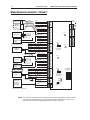
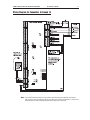
Honeywell PRO-2200 Two Reader Module is a versatile access control device designed to enhance the security of your premises. It accommodates two readers, allowing for flexible entry options such as badge, PIN, or a combination of both. With its multiple communication interfaces, the PRO-2200 seamlessly integrates with various access control systems, providing a reliable and efficient solution for managing access rights and monitoring出入.
Honeywell PRO-2200 Two Reader Module is a versatile access control device designed to enhance the security of your premises. It accommodates two readers, allowing for flexible entry options such as badge, PIN, or a combination of both. With its multiple communication interfaces, the PRO-2200 seamlessly integrates with various access control systems, providing a reliable and efficient solution for managing access rights and monitoring出入.


-
 1
1
-
 2
2
-
 3
3
-
 4
4
-
 5
5
-
 6
6
-
 7
7
-
 8
8
-
 9
9
-
 10
10
-
 11
11
-
 12
12
-
 13
13
-
 14
14
-
 15
15
-
 16
16
-
 17
17
-
 18
18
-
 19
19
-
 20
20


Honeywell PRO-2200 Two Reader Module is a versatile access control device designed to enhance the security of your premises. It accommodates two readers, allowing for flexible entry options such as badge, PIN, or a combination of both. With its multiple communication interfaces, the PRO-2200 seamlessly integrates with various access control systems, providing a reliable and efficient solution for managing access rights and monitoring出入.
Ask a question and I''ll find the answer in the document
Finding information in a document is now easier with AI
Related papers
Other documents
-
 Lenel OnGuard Hardware Installation Manual
-
 Lenel LNL-3300-M5 Installation guide
-
Northern N-1000-IV Installation And Programming Manual
-
Johnson Controls CK721-A Operating instructions
-
 American Dynamics KT-400 User manual
-
Ingersoll-Rand SCHLAGE HP-4000 User manual
-
Acroprint HandPunch 3000/4000 User manual
-
Secura Key SK-ACPE User manual
-
-
 GENETEC SYNERGIS Synergis IX SY-SIX-RDM2-DIN-485 Installation guide


