Crestron CEN-WAP-ABG-CM Installation guide
- Category
- Bridges & repeaters
- Type
- Installation guide
This manual is also suitable for

Crestron CEN-WAP-ABG
802.11a/b/g Wireless Access Points
Operations & Installation Guide

This document was prepared and written by the Technical Documentation department at:
Crestron Electronics, Inc.
15 Volvo Drive
Rockleigh, NJ 07647
1-888-CRESTRON
All brand names, product names and trademarks are the property of their respective owners.
©2009 Crestron Electronics, Inc.

Crestron CEN-WAP-ABG 802.11a/b/g Wireless Access Points
Contents
802.11a/b/g Wireless Access Points: CEN-WAP-ABG 1
Introduction ...............................................................................................................................1
Features and Functions................................................................................................1
Specifications ..............................................................................................................3
Physical Description....................................................................................................5
Industry Compliance .................................................................................................10
Setup ........................................................................................................................................ 11
Network Wiring.........................................................................................................11
Supplied Hardware....................................................................................................11
Installation.................................................................................................................11
Hardware Hookup .....................................................................................................14
Configuration...........................................................................................................................15
Accessing the Configuration Utility ..........................................................................15
Using Setup Wizard Configuration Mode ................................................................. 18
Using Custom Settings Configuration Mode............................................................. 20
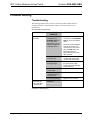
Problem Solving ...................................................................................................................... 48
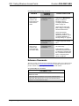
Troubleshooting.........................................................................................................48
Reference Documents................................................................................................ 50
Further Inquiries........................................................................................................51
Future Updates ..........................................................................................................51
Software License Agreement...................................................................................................52
Return and Warranty Policies.................................................................................................. 54
Merchandise Returns / Repair Service ......................................................................54
CRESTRON Limited Warranty................................................................................. 54
Operations & Installation Guide – DOC. 6695C Contents • i


Crestron CEN-WAP-ABG 802.11a/b/g Wireless Access Points
802.11a/b/g Wireless Access
Points: CEN-WAP-ABG
Introduction
NOTE: Unless otherwise noted, references in this manual to CEN-WAP-ABG
apply to both the CEN-WAP-ABG-1G and CEN-WAP-ABG-CM wireless
access points.
CEN-WAP-ABG wireless access points enable wireless communication for
Crestron
®
Wi-Fi touchpanels, 2-Series control systems, computers, and other
devices. With IEEE 802.11a/b/g support, easy setup, flush-mount installation, and
enterprise level security and management capabilities, a CEN-WAP-ABG delivers
an ideal wireless access point solution for any application.
Features and Functions
• Supports 802.11a, 802.11b, and 802.11g protocols
• Single-wire hookup using Power over Ethernet (PoE)
• Secure network with no configuration required
• Web-browser configuration and management
• Enterprise level security
• Built-in DHCP server
• MAC address filtering
• On-board event logging
• SNMP and UPnP configuration and management
• Bridge mode for wireless LAN-to-LAN capability
• Ethernet control system interface
• Front-panel LAN pass-through port (CEN-WAP-ABG-1G only)
• Attractive flush wall mount (CEN-WAP-ABG-1G) or low-profile
ceiling mount (CEN-WAP-ABG-CM) design
Operations & Installation Guide – DOC. 6695C 802.11a/b/g Wireless Access Points: CEN-WAP-ABG • 1

802.11a/b/g Wireless Access Points Crestron CEN-WAP-ABG
Single-Wire Hookup
Power over Ethernet (PoE) capability powers a CEN-WAP-ABG through the LAN
wiring, eliminating the need for a separate power supply. A Category 5 (CAT5)
cable simply connects the wireless access point to a PoE injector (PWE-4803RU),
allowing for installation at a convenient location apart from the access point.
Alternatively, using the Crestron five-port PoE switch (CEN-SW-POE-5), up to four
access points can be powered from a single location, simplifying design and wiring.
A third-party PoE source device can also be used to power the access point.
No Configuration Required
Using a CEN-WAP-ABG, a secure Wi-Fi touchpanel connection can be made
quickly and easily right out of the box. Each wireless access point ships with a
unique network name and network key printed on a removable sticker on the front of
the unit. Entering this information into the touchpanel is all that is required to
complete the connection. Multiple access points can be installed in the same vicinity
without causing any connection problems.
Web-Browser Configuration and Management
For applications that require a customized configuration, a CEN-WAP-ABG features
built-in browser-based management tools. From any Web browser, the easy setup
wizard lets you simply select the scenario, such as a standalone network or a high-
security environment, and applies the necessary configuration settings for you. After
configuration using the setup wizard is completed, step-by-step instructions are then
provided for connecting Crestron Wi-Fi touchpanels to the network. Beyond the
wizard, there are more comprehensive configuration and security settings available
for advanced users and system administrators.
Enterprise Level Security
For a secure wireless network in the home or office, a CEN-WAP-ABG supports up
to 152-bit WEP encryption as well as more advanced WPA and WPA2
authentication and encryption methods. RADIUS certificates are also supported for a
true enterprise level solution.
DHCP Server
A CEN-WAP-ABG can assign IP addresses automatically to touchpanels and other
client devices using DHCP (Dynamic Host Configuration Protocol).
MAC Address Filtering
Unauthorized devices can be prevented from joining the wireless network,
maximizing bandwidth for control and streaming AV signals to support only the
touchpanels, computers, and other devices that you specify. MAC filtering increases
security without switching to an authentication method with more overhead.
Event Logging
To assist in troubleshooting, a CEN-WAP-ABG keeps a history of the last 500 client
connections, disconnections, and failure events, and includes helpful details such as
the reason for a disconnect or failure.
2 • 802.11a/b/g Wireless Access Points: CEN-WAP-ABG Operations & Installation Guide – DOC. 6695C

Crestron CEN-WAP-ABG 802.11a/b/g Wireless Access Points
Bridge Mode
This useful feature allows a CEN-WAP-ABG to be used to add wireless connectivity
to any device with an Ethernet port, or to extend a LAN via a wireless link whenever
a CAT5 wire cannot be run.
Ethernet Pass-Through (CEN-WAP-ABG-1G only)
An Ethernet port is available on the front of the CEN-WAP-ABG-1G, providing a
convenient LAN connection for computers and touchpanels. This port can be
disabled via software if not required.
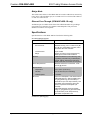
Specifications
Specifications for a CEN-WAP-ABG are listed in the following table.
CEN-WAP-ABG Specifications
SPECIFICATION DETAILS
RF Wireless
RF Transceiver
IEEE 802.11a/b/g; 5.8 or 2.4 GHz 2-way RF;
64, 128, and 152-bit WEP encryption; WPA
and WAP2 with TKIP and AES
Transmit Power Up to 19 dBm
Range
30 feet (10 meters); range and speed vary
based upon environmental conditions
Ethernet
10BaseT/100BaseTX, auto-switching, auto-
negotiating, auto-discovery, full/half duplex,
TCP/IP, UDP/IP, DHCP client and server,
SNMP, IEEE 802.3u and 802.3af compliant
Power Requirements
IEEE 802.3af Power over Ethernet, 3.3 W
(70 mA) @ 48 VDC
Environmental
Temperature 32º to 104º F (0º to 40º C)
Humidity 10% to 90% RH (non-condensing)
Heat Dissipation 11 BTU/Hr
Enclosure Injection-molded plastic, white textured finish
CEN-WAP-ABG-1G: Wall mountable using
a 1-gang plaster ring (recommended) or
electrical box (2.5 inch deep minimum), rack
mountable using a third-party rack mount
panel*; requires Decora faceplate (not
included)
CEN-WAP-ABG-CM: Ceiling mountable
using a 1-gang plaster ring (recommended)
or electrical box (2 inch deep minimum),
removable and paintable cover
(Continued on following page)
Operations & Installation Guide – DOC. 6695C 802.11a/b/g Wireless Access Points: CEN-WAP-ABG • 3

802.11a/b/g Wireless Access Points Crestron CEN-WAP-ABG
CEN-WAP-ABG Specifications (Continued)
SPECIFICATION DETAILS
Dimensions
CEN-WAP-ABG-1G
(without antenna)
Height 4.14 in (10.51 cm)
Width 1.74 in (4.40 cm)
Depth
CEN-WAP-ABG-CM
2.87 in (7.29 cm)
Diameter 4.73 in (12.00 cm)
Depth 2.53 in (6.43 cm)
Weight CEN-WAP-ABG-1G: 5 oz (133 g)
CEN-WAP-ABG-CM: 6 oz (168 g)
* Middle Atlantic HBL1-722243 or equivalent rack mount panel recommended. Note unit dimensions
when specifying any other rack mount kit.
NOTE: Crestron software and any files on the website are for authorized Crestron
dealers and Crestron Authorized Independent Programmers (CAIP) only. New users
may be required to register to obtain access to certain areas of the site (including the
FTP site).
4 • 802.11a/b/g Wireless Access Points: CEN-WAP-ABG Operations & Installation Guide – DOC. 6695C

Crestron CEN-WAP-ABG 802.11a/b/g Wireless Access Points
Physical Description
This section provides information about the connections, controls and indicators
available on your CEN-WAP-ABG.
CEN-WAP-ABG-1G
Information about the connections, controls and indicators of the
CEN-WAP-ABG-1G follows.
CEN-WAP-ABG-1G Physical View (Front and Rear)
CEN-WAP-ABG-1G Overall Dimensions (Front View)
4.14 in
(10.51 cm)
2.84 in
(7.20 cm)
2.60 in
(6.60 cm)
1.74 in
(4.40 cm)
1.29 in
(3.28 cm)
Operations & Installation Guide – DOC. 6695C 802.11a/b/g Wireless Access Points: CEN-WAP-ABG • 5

802.11a/b/g Wireless Access Points Crestron CEN-WAP-ABG
CEN-WAP-ABG-1G Overall Dimensions (Side View without Antenna, Left)
2.16 in
(5.47 cm)
0.30 in
(0.77 cm)
0.61 in
(1.55 cm)
0.10 in
(0.24 cm)
CEN-WAP-ABG-1G Overall Dimensions (Side View with Antenna, Left)
6.21 in
(15.75 cm)
3.44 in
(8.72 cm)
6 • 802.11a/b/g Wireless Access Points: CEN-WAP-ABG Operations & Installation Guide – DOC. 6695C

Crestron CEN-WAP-ABG 802.11a/b/g Wireless Access Points
CEN-WAP-ABG-1G Connectors, Controls & Indicators (Front and Rear)
1
2
3
4
5
6
Connectors, Controls & Indicators
# CONNECTORS,
CONTROLS &
INDICATORS
DESCRIPTION
1 Antenna (1) Connects to supplied antenna.
2 LAN
(1) Green LED: Solid green indicates link
status of the rear Ethernet port;
Flashing green indicates Ethernet activity
through the rear Ethernet port.
3 Reset
(1) Recessed push button that resets the
device.*
4
Wi-Fi
(1) Green LED: Solid green indicates
wireless network connection;
Flashing green indicates wireless data
activity.
5
AMBER
LED
GREEN
LED
(1) 8-wire RJ-45 connector with 2 LED
indicators;
10BaseT/100BaseTX Ethernet port;
Amber LED indicates 100BaseT link status;
Solid green LED indicates link status;
Flashing green LED indicates Ethernet
activity.
Connects to local wired Ethernet equipment
(optional).
6
NETWORK PoE
NETWORK
PoE
(1) 8-wire RJ-45 connector;
10BaseT/100BaseTX Ethernet and PoE
input port;
Connects to IEEE 802.3af-compliant PoE
power source.
* To press the Reset button, use the end of a paper clip. Pressing the Reset button for eight seconds
resets the configuration settings of the unit to factory-default settings.
Operations & Installation Guide – DOC. 6695C 802.11a/b/g Wireless Access Points: CEN-WAP-ABG • 7

802.11a/b/g Wireless Access Points Crestron CEN-WAP-ABG
CEN-WAP-ABG-CM
Information about the connections, controls and indicators of the
CEN-WAP-ABG-CM follows.
CEN-WAP-ABG-CM Physical View (Front and Rear)
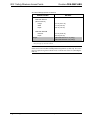
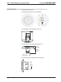
CEN-WAP-ABG-CM Overall Dimensions (Top View)
4.73 in
(12.00 cm)
1.69 in
(4.28 cm)
CEN-WAP-ABG-CM Overall Dimensions (Bottom View)
0.80 in
(1.93 cm)
1.60 in
(4.05 cm)
1.80 in
(4.50 cm)
CEN-WAP-ABG-CM Overall Dimensions (Side View, Right)
2.80 in
(7.05 cm)
8 • 802.11a/b/g Wireless Access Points: CEN-WAP-ABG Operations & Installation Guide – DOC. 6695C

Crestron CEN-WAP-ABG 802.11a/b/g Wireless Access Points
CEN-WAP-ABG-CM Connectors, Control & Indicators (Front and Rear)
1
2
3
4
Connectors, Control & Indicators
# CONNECTORS,
CONTROL &
INDICATORS
DESCRIPTION
1 LAN
(1) Green LED: Solid green indicates link
status of the Ethernet port;
Flashing green indicates Ethernet activity
through the Ethernet port.
2 Reset
(1) Recessed push button that resets the
device.*
3
Wi-Fi
(1) Green LED: Solid green indicates
wireless network connection;
Flashing green indicates wireless data
activity.
4
NETWORK PoE
NETWORK
PoE
(1) 8-wire RJ-45 connector;
10BaseT/100BaseTX Ethernet and PoE
input port;
Connects to IEEE 802.3af-compliant PoE
power source.
* To press the Reset button, use the end of a paper clip. Pressing the Reset button for eight seconds
resets the configuration settings of the unit to factory-default settings.
Operations & Installation Guide – DOC. 6695C 802.11a/b/g Wireless Access Points: CEN-WAP-ABG • 9

802.11a/b/g Wireless Access Points Crestron CEN-WAP-ABG
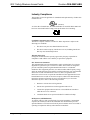
Industry Compliance
This product is Listed to applicable UL Standards and requirements by Underwriters
Laboratories Inc.
(E312979)
As of the date of manufacture, the CEN-WAP-ABG-1G and CEN-WAP-ABG-CM
have been tested and found to comply with specifications for CE marking.
FCC ID: MXF-M930907
Compliance Statement (Part 15.19)
This device complies with Part 15 of the FCC Rules. Operation is subject to the
following two conditions:
1. This device may not cause harmful interference and
2. This device must accept any interference received, including interference
that may cause undesired operation.
Warning (Part 15.21)
Changes or modifications not expressly approved by the party responsible for
compliance could void the user’s authority to operate the equipment.
FCC Interference Statement
This equipment has been tested and found to comply with the limits for a Class B
digital device, pursuant to part 15 of the FCC Rules. These limits are designed to
provide reasonable protection against harmful interference in a residential
installation. This equipment generates, uses and can radiate radio frequency energy
and if not installed and used in accordance with the instructions, may cause harmful
interference to radio communications. However, there is no guarantee that
interference will not occur in a particular installation. If this equipment does cause
harmful interference to radio or television reception, which can be determined by
turning the equipment off and on, the user is encouraged to try to correct the
interference by one or more of the following measures:
1. Reorient or relocate the receiving antenna.
2. Increase the separation between the equipment and receiver.
3. Connect the equipment into an outlet on a circuit different from that to
which the receiver is connected.
4. Consult the dealer or an experienced radio/TV technician for help.
RF Exposure (OET Bulletin 65)
To comply with FCC’s RF exposure limits for general population / uncontrolled
exposure, the antenna(s) used for this transmitter must be installed to provide a
separation distance of at least 20 cm from all persons and must not be co-located or
operating in conjunction with any other antenna or transmitter.
10 • 802.11a/b/g Wireless Access Points: CEN-WAP-ABG Operations & Installation Guide – DOC. 6695C

Crestron CEN-WAP-ABG 802.11a/b/g Wireless Access Points
Setup
Network Wiring
When wiring the Ethernet network, use CAT5 wiring. CAT5 wiring is a twisted pair
cable designed for Ethernet networks. These networks operate at speeds of up to 100
Megabits per second (Mbps) using the 100BaseT standard.
For information on connecting Ethernet devices in a Crestron system, refer to the
latest version of the Crestron e-Control
®
Reference Guide (Doc. 6052), which is
available for download from the Crestron website (www.crestron.com/manuals).
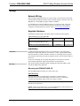
Supplied Hardware
The hardware supplied with a CEN-WAP-ABG is listed in the following table.
Supplied Hardware for a CEN-WAP-ABG
DESCRIPTION PART NUMBER QUANTITY
2.4/5.8 GHz White Omnidirectional
Antenna (CEN-WAP-ABG-1G only)
2021159 1
#6-32 x ¾”, Pan Head Phillips Screws 2022188 2
Installation
Ventilation
A CEN-WAP-ABG should be used in a well-ventilated area. The venting holes
should not be obstructed under any circumstances. Contact with thermal insulating
materials should be avoided on all sides of the device. If installing the access point
in an insulated wall/ceiling, one inch of insulation must be removed from all sides of
the device.
To prevent overheating, do not operate this product in an area that exceeds the
environmental temperature range listed in the table of specifications.
Mounting
This section provides information about mounting the CEN-WAP-ABG-1G and
CEN-WAP-ABG-CM as applicable.
Mounting the CEN-WAP-ABG-1G
The CEN-WAP-ABG-1G mounts to a wall or into a rack.
Wall Mounting
The CEN-WAP-ABG-1G mounts into a one-gang low-voltage bracket or
electrical box. The recommended depth of the electrical box is a minimum of
2.5 inches. The maximum voltage of the access point is 48 VDC.
NOTE: To increase airflow, it is recommended that a low-voltage bracket be used
instead of an electrical box.
NOTE: For the best possible range, it is recommended that you mount the device as
high as possible and as far away as possible from metal.
Operations & Installation Guide – DOC. 6695C 802.11a/b/g Wireless Access Points: CEN-WAP-ABG • 11

802.11a/b/g Wireless Access Points Crestron CEN-WAP-ABG
To mount the access point into a low-voltage bracket or electrical box (refer to the
illustration below):
1. Orient the access point properly, and then place the device into the bracket or
electrical box.
2. Attach the access point to the bracket or electrical box using the two #6-32 x ¾”
Phillips pan head screws included with the access point.
3. Attach the desired Decora
®
faceplate (not included).
CEN-WAP-ABG-1G Wall Mounting (Low-Voltage Bracket Shown)
#6-32 x ¾”
Phillips Pan Head
Screws
Rack Mounting
The CEN-WAP-ABG-1G mounts horizontally into a rack and occupies 1U
(1.75 inches) of rack space.
NOTE: It is recommended that the access point be mounted into a rack only if the
connected Wi-Fi devices are to be used less than 20 feet away from the access point
and have line of sight to the access point.
NOTE: For the best possible range, it is recommended that you mount the device
into the topmost rack space.
To mount the unit, use the Middle Atlantic HBL1-722243 or equivalent rack mount
panel. For ordering information, contact Middle Atlantic Products, Inc.
(http://www.middleatlantic.com).
Mounting the CEN-WAP-ABG-CM
The CEN-WAP-ABG-CM mounts into a one-gang low-voltage bracket or electrical
box in the ceiling. The recommended depth of the electrical box is a minimum of
two inches. The maximum voltage of the access point is 48 VDC.
NOTE: To increase airflow, it is recommended that a low-voltage bracket be used
instead of an electrical box.
NOTE: For the best possible range, it is recommended that you mount the device as
far away as possible from metal.
12 • 802.11a/b/g Wireless Access Points: CEN-WAP-ABG Operations & Installation Guide – DOC. 6695C

Crestron CEN-WAP-ABG 802.11a/b/g Wireless Access Points
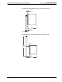
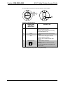
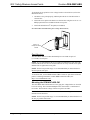
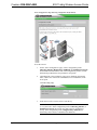
To mount the CEN-WAP-ABG-CM to a ceiling:
1. Remove the cover by inserting a screwdriver into the notch at the bottom of the
access point and pushing the base of the unit upward until it detaches from
the cover.
CEN-WAP-ABG-CM Cover Removal
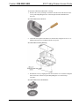
2. Attach the access point to the bracket or electrical box using the two #6-32 x ¾”
Phillips pan head screws included with the access point.
CEN-WAP-ABG-CM Ceiling Mounting
3. Reattach the cover by aligning the four tabs inside the cover with the rectangular
holes in the base of the access point and pushing the cover until it snaps
into place.
CEN-WAP-ABG-CM Cover Reattachment
Operations & Installation Guide – DOC. 6695C 802.11a/b/g Wireless Access Points: CEN-WAP-ABG • 13

802.11a/b/g Wireless Access Points Crestron CEN-WAP-ABG
Hardware Hookup
Make the necessary connections as called out in the following sections. Apply power after all
connections have been made.
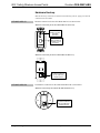
CEN-WAP-ABG-1G
Hardware connections for the CEN-WAP-ABG-1G are shown below.
Hardware Connections for the CEN-WAP-ABG-1G (Front View)
ANTENNA:
FROM 2.4/5.8 GHz
ANTENNA
(INCLUDED)
ETHERNET:
10BaseT/100BaseTX
ETHERNET TO LAN
(OPTIONAL)
Hardware Connections for the CEN-WAP-ABG-1G (Rear View)
NETWORK PoE:
TO 10BaseT/100BaseTX
802.3af-COMPLIANT
POWER SOURCE
CEN-WAP-ABG-CM
The hardware connection for the CEN-WAP-ABG-CM is shown below.
Hardware Connection for the CEN-WAP-ABG-CM (Rear View)
NETWORK PoE:
TO 10BaseT/100BaseTX
802.3af-COMPLIANT
POWER SOURCE
14 • 802.11a/b/g Wireless Access Points: CEN-WAP-ABG Operations & Installation Guide – DOC. 6695C

Crestron CEN-WAP-ABG 802.11a/b/g Wireless Access Points
Configuration
Have a question or comment about Crestron software?
Answers to frequently asked questions (FAQs) can be viewed in the Online Help
section of the Crestron website. To post a question or view questions you have
submitted to Crestron’s True Blue Support, log in at http://support.crestron.com.
First-time users will need to establish a user account.
NOTE: A CEN-WAP-ABG is designed to be functional right out of the box.
Configure the CEN-WAP-ABG only if customized settings are desired.
If customized settings are not desired, refer to the latest version of the
CEN-WAP-ABG-1G Quickstart Guide (Doc. 6693) or the CEN-WAP-ABG-CM
Quickstart Guide (Doc. 6787), which is available from the Crestron website, for
guidelines to connect the access point to Crestron Wi-Fi touchpanels.
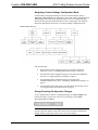
A CEN-WAP-ABG provides a Web-based utility that can be accessed from a Web
browser or from the Crestron Toolbox™. The utility offers two configuration modes:
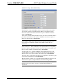
• Setup Wizard configuration mode, which provides instructions and
automated access to the screens necessary to set up a particular
configuration or application scenario.
• Custom Settings configuration mode, which allows more advanced
configuration than that provided by the wizard and also allows monitoring
of the status of the access point.
Accessing the Configuration Utility
NOTE: Configuration of a CEN-WAP-ABG must be performed from a computer
whose IP address is in the same IP subnet. The default configuration of the access
point allows the IP address of the access point to be automatically assigned by a
DHCP (Dynamic Host Configuration Protocol) server on the local area network.
If a DHCP server does not exist on the network and 45 seconds have elapsed since
the access point was powered on, the IP address of the access point defaults to
192.168.1.222 and the subnet mask defaults to 255.255.255.0.
You can access the configuration utility from a Web browser or from the Crestron
Toolbox:
• You can access the configuration utility from a Web browser if you know
the IP address or host name of the access point.
NOTE: The default host name of the access point is CEN-WAP-ABG-1G.
For additional information, refer to “Using a Web Browser” on page 16.
• You can access the configuration utility from the Crestron Toolbox if the
access point is configured to operate in DHCP mode (default configuration).
The Crestron ToolBox automatically discovers the IP address of the access
point. For additional information, refer to “Using the Crestron ToolBox” on
page 16.
Operations & Installation Guide – DOC. 6695C 802.11a/b/g Wireless Access Points: CEN-WAP-ABG • 15

802.11a/b/g Wireless Access Points Crestron CEN-WAP-ABG
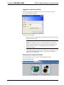
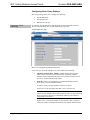
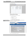
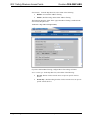
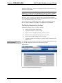
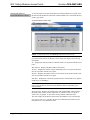
Using a Web Browser
To access the configuration utility from a Web browser:
1. Start your Web browser.
2. Go to the IP address or host name of the access point.
NOTE: If the default Web management port number of 80 has been
changed, you must append the port number to the IP address by entering a
colon followed by the new port number. If, for example, the IP address is
192.168.10.225 and the Web management port number has been changed
from 80 to 150, go to http://192.168.10.225:150.
For information about changing the Web management port number, refer to
“Configuring External Control Settings” on page 40.
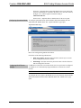
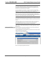
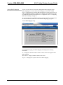
The user name and password window opens, allowing you to log in to the
access point. For log-in information, refer to “Logging In to the Access
Point” on page 17.
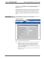
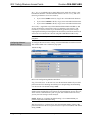
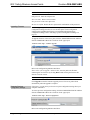
Using the Crestron ToolBox
NOTE: To be able to use the Crestron Toolbox to access the configuration utility of
the access point, the UPnP (Universal Plug and Play) Ethernet protocol configuration
setting of the access point must be enabled. The UPnP protocol is enabled by default.
For additional information, refer to “Configuring External Control Settings”
on page 40.
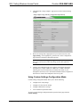
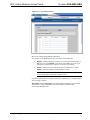
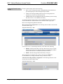
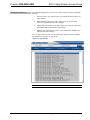
To access the configuration utility from the Crestron Toolbox:
1. Open the Crestron Toolbox.
2. From the Tools menu, select Device Discovery Tool.
NOTE: You can also access the Device Discovery Tool by clicking the
Device Discovery Tool button ( ) in the toolbar.
NOTE: The security software running on your computer may send you a
program alert regarding the attempt of Crestron Toolbox to connect to the
network. You must allow the connection so that the Device Discovery tool
can be used.
3. From the device list on the left-hand side of the screen, select the UPnP
name of the access point. The default UPnP name is CEN-WAP-ABG-1G.
The user name and password window opens, allowing you to log in to the
access point. For log-in information, refer to “Logging In to the Access
Point” on page 17.
16 • 802.11a/b/g Wireless Access Points: CEN-WAP-ABG Operations & Installation Guide – DOC. 6695C
Page is loading ...
Page is loading ...
Page is loading ...
Page is loading ...
Page is loading ...
Page is loading ...
Page is loading ...
Page is loading ...
Page is loading ...
Page is loading ...
Page is loading ...
Page is loading ...
Page is loading ...
Page is loading ...
Page is loading ...
Page is loading ...
Page is loading ...
Page is loading ...
Page is loading ...
Page is loading ...
Page is loading ...
Page is loading ...
Page is loading ...
Page is loading ...
Page is loading ...
Page is loading ...
Page is loading ...
Page is loading ...
Page is loading ...
Page is loading ...
Page is loading ...
Page is loading ...
Page is loading ...
Page is loading ...
Page is loading ...
Page is loading ...
Page is loading ...
Page is loading ...
Page is loading ...
Page is loading ...
-
 1
1
-
 2
2
-
 3
3
-
 4
4
-
 5
5
-
 6
6
-
 7
7
-
 8
8
-
 9
9
-
 10
10
-
 11
11
-
 12
12
-
 13
13
-
 14
14
-
 15
15
-
 16
16
-
 17
17
-
 18
18
-
 19
19
-
 20
20
-
 21
21
-
 22
22
-
 23
23
-
 24
24
-
 25
25
-
 26
26
-
 27
27
-
 28
28
-
 29
29
-
 30
30
-
 31
31
-
 32
32
-
 33
33
-
 34
34
-
 35
35
-
 36
36
-
 37
37
-
 38
38
-
 39
39
-
 40
40
-
 41
41
-
 42
42
-
 43
43
-
 44
44
-
 45
45
-
 46
46
-
 47
47
-
 48
48
-
 49
49
-
 50
50
-
 51
51
-
 52
52
-
 53
53
-
 54
54
-
 55
55
-
 56
56
-
 57
57
-
 58
58
-
 59
59
-
 60
60


Crestron CEN-WAP-ABG-CM Installation guide
- Category
- Bridges & repeaters
- Type
- Installation guide
- This manual is also suitable for
Ask a question and I''ll find the answer in the document
Finding information in a document is now easier with AI
Related papers
-
Crestron CEN-WAP-ABG User guide
-
Crestron CEN-WAP-ABG User manual
-
-
-
-
Crestron TST-600 Specification
-
-
-
-
Other documents
-
 Crestron electronic CEN-SW-POE-5 User manual
-
LevelOne WAP-0005 Quick Install Manual
-
-
Belkin F5D7130 User manual
-
-
Planet 802.11g Wireless Access Point / Bridge WAP-4000 User manual
-
Poewit WAP-1 User guide
-
Poewit WAP-2O User guide
-
-
Eaton iLIGHT TSE55 Installation guide
