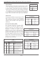
Supermicro 7047AX-72RF User manual
- Category
- Server barebones
- Type
- User manual
This manual is also suitable for

SUPERSERVER
7047AX-TRF
7047AX-72RF
SUPER
®
USER’S MANUAL
Revision 1.0

The information in this User’s Manual has been carefully reviewed and is believed to be accurate.
The vendor assumes no responsibility for any inaccuracies that may be contained in this document,
makes no commitment to update or to keep current the information in this manual, or to notify any
person or organization of the updates. Please Note: For the most up-to-date version of this
manual, please see our web site at www.supermicro.com.
Super Micro Computer, Inc. ("Supermicro") reserves the right to make changes to the product
described in this manual at any time and without notice. This product, including software and
documentation, is the property of Supermicro and/or its licensors, and is supplied only under a
license. Any use or reproduction of this product is not allowed, except as expressly permitted by
the terms of said license.
IN NO EVENT WILL SUPERMICRO BE LIABLE FOR DIRECT, INDIRECT, SPECIAL, INCIDENTAL,
SPECULATIVE OR CONSEQUENTIAL DAMAGES ARISING FROM THE USE OR INABILITY TO
USE THIS PRODUCT OR DOCUMENTATION, EVEN IF ADVISED OF THE POSSIBILITY OF
SUCH DAMAGES. IN PARTICULAR, SUPERMICRO SHALL NOT HAVE LIABILITY FOR ANY
HARDWARE, SOFTWARE, OR DATA STORED OR USED WITH THE PRODUCT, INCLUDING THE
COSTS OF REPAIRING, REPLACING, INTEGRATING, INSTALLING OR RECOVERING SUCH
HARDWARE, SOFTWARE, OR DATA.
Any disputes arising between manufacturer and customer shall be governed by the laws of Santa
Clara County in the State of California, USA. The State of California, County of Santa Clara shall
be the exclusive venue for the resolution of any such disputes. Super Micro's total liability for all
claims will not exceed the price paid for the hardware product.
FCC Statement: This equipment has been tested and found to comply with the limits for a Class
A digital device pursuant to Part 15 of the FCC Rules. These limits are designed to provide
reasonable protection against harmful interference when the equipment is operated in a commercial
environment. This equipment generates, uses, and can radiate radio frequency energy and, if not
installed and used in accordance with the manufacturer’s instruction manual, may cause harmful
interference with radio communications. Operation of this equipment in a residential area is likely
to cause harmful interference, in which case you will be required to correct the interference at your
own expense.
California Best Management Practices Regulations for Perchlorate Materials: This Perchlorate
warning applies only to products containing CR (Manganese Dioxide) Lithium coin cells. “Perchlorate
Material-special handling may apply. See www.dtsc.ca.gov/hazardouswaste/perchlorate”
WARNING: Handling of lead solder materials used in this
product may expose you to lead, a chemical known to
the State of California to cause birth defects and other
reproductive harm.
Manual Revision 1.0
Release Date: October 19, 2012
Unless you request and receive written permission from Super Micro Computer, Inc., you may not
copy any part of this document.
Information in this document is subject to change without notice. Other products and companies
referred to herein are trademarks or registered trademarks of their respective companies or mark
holders.
Copyright © 2012 by Super Micro Computer, Inc.
All rights reserved.
Printed in the United States of America

Preface
About This Manual
This manual is written for professional system integrators and PC technicians.
It provides information for the installation and use of the SuperServer 7047AX-
TRF/7047AX-72RF server. Installation and maintenance should be performed by
experienced technicians only.
The SuperServer 7047AX-TRF/7047AX-72RF is based on the CSE-747TG-
R1K28B-SQ 4U/Tower rackmount server chassis and the Super X9DAX-7F/iF
serverboard. Please refer to our web site for an up-to-date list of supported operating
systems, processors and memory.
Manual Organization
Chapter 1: Introduction
The rst chapter provides a checklist of the main components included with
the server system and describes the main features of the Super X9DAX-7F/iF
serverboard and the CSE-747TG-R1K28B-SQ chassis.
Chapter 2: Server Installation
This chapter describes the steps necessary to install the system into a rack and
check out the server conguration prior to powering up the system. If your server
was ordered without the processor and memory components, this chapter will refer
you to the appropriate sections of the manual for their installation.
Chapter 3: System Interface
Refer to this chapter for details on the system interface, which includes the functions
and information provided by the control panel on the chassis as well as other LEDs
located throughout the system.
Chapter 4: System Safety
You should thoroughly familiarize yourself with this chapter for a general overview
of safety precautions that should be followed when installing and servicing the
system.
Chapter 5: Advanced Serverboard Setup
Chapter 5 provides detailed information on the X9DAX-7F/iF serverboard,
including the locations and functions of connectors, headers and jumpers. Refer
iii
Preface

SUPERSERVER 7047R-TXRF User's Manual
iv
to this chapter when adding or removing processors or main memory and when
reconguring the serverboard.
Chapter 6: Advanced Chassis Setup
Refer to Chapter 6 for detailed information on the CSE-747TG-R1K28B-SQ 4U/
Tower rackmount server chassis. You should follow the procedures given in this
chapter when installing, removing or reconguring SATA or peripheral drives and
when replacing system power supply units and cooling fans.
Chapter 7: BIOS
The BIOS chapter includes an introduction to BIOS and provides detailed information
on running the CMOS Setup Utility.
Appendix A: BIOS POST Messages
Appendix B: System Specications

v
Table of Contents
Chapter 1 Introduction
1-1 Overview ......................................................................................................... 1-1
1-2 Serverboard Features ..................................................................................... 1-2
Processors ...................................................................................................... 1-2
Memory ........................................................................................................... 1-2
SAS ................................................................................................................. 1-2
Serial ATA ....................................................................................................... 1-2
PCI Expansion Slots ....................................................................................... 1-2
Rear I/O Ports ................................................................................................. 1-3
IPMI ................................................................................................................. 1-3
1-3 Chassis Features ............................................................................................ 1-3
System Power ................................................................................................. 1-3
Mounting Rails (optional) ................................................................................ 1-3
Hard Drive/Drive Bays .................................................................................... 1-3
Control Panel .................................................................................................. 1-4
Cooling System ............................................................................................... 1-4
1-5 Contacting Supermicro .................................................................................... 1-5
Chapter 2 Workstation Installation
2-1 Overview ......................................................................................................... 2-1
2-2 Unpacking the System .................................................................................... 2-1
2-3 Preparing for Setup ......................................................................................... 2-2
Choosing a Setup Location ............................................................................. 2-2
Rack Precautions ............................................................................................ 2-2
Workstation Precautions ................................................................................. 2-2
Rack Mounting Considerations ....................................................................... 2-3
Ambient Operating Temperature ................................................................ 2-3
Reduced Airow ......................................................................................... 2-3
Mechanical Loading ................................................................................... 2-3
Circuit Overloading ..................................................................................... 2-3
Reliable Ground ......................................................................................... 2-4
2-4 Installing the Chassis onto a Rack ................................................................. 2-4
Removing the Chassis Cover and Feet .......................................................... 2-4
Identifying the Sections of the Rack Rails ...................................................... 2-5
Installing the Chassis Handles and Inner Rails .............................................. 2-7
Installing the Outer Rails to the Rack ............................................................. 2-8
Installing the Chassis into a Rack................................................................. 2-10
2-5 Tower Mounting Instructions ..........................................................................2-11
SUPERSERVER 7047R-TXRF User's Manual

vi
Table of Contents
Installing the Chassis Cover ..........................................................................2-11
Installing Feet on the Chassis ...................................................................... 2-12
Chapter 3 System Interface
3-1 Overview ......................................................................................................... 3-1
3-2 Control Panel Buttons ..................................................................................... 3-2
Power .............................................................................................................. 3-2
Reset ............................................................................................................... 3-2
3-3 Control Panel LEDs ........................................................................................ 3-2
HDD ................................................................................................................. 3-2
NIC1 ................................................................................................................ 3-3
NIC2 ................................................................................................................ 3-3
Overheat/Fan Fail ........................................................................................... 3-3
Power Fail ....................................................................................................... 3-3
3-4 Drive Carrier LEDs .......................................................................................... 3-4
Chapter 4 Standardized Warning Statements for AC Systems
4-1 About Standardized Warning Statements ....................................................... 4-1
Warning Denition ........................................................................................... 4-1
Installation Instructions .................................................................................... 4-4
Circuit Breaker ................................................................................................ 4-5
Power Disconnection Warning ........................................................................ 4-6
Equipment Installation ..................................................................................... 4-8
Restricted Area ................................................................................................ 4-9
Battery Handling ............................................................................................ 4-10
Redundant Power Supplies .......................................................................... 4-12
Backplane Voltage ........................................................................................ 4-13
Comply with Local and National Electrical Codes ........................................ 4-14
Product Disposal ........................................................................................... 4-15
Hot Swap Fan Warning ................................................................................. 4-16
Power Cable and AC Adapter ...................................................................... 4-18
Chapter 5 Advanced Serverboard Setup
5-1 Handling the Serverboard ............................................................................... 5-1
Precautions ..................................................................................................... 5-1
Unpacking ....................................................................................................... 5-2
5-2 Connecting Cables .......................................................................................... 5-2
Connecting Data Cables ................................................................................. 5-2
Connecting Power Cables .............................................................................. 5-2
Connecting the Control Panel ......................................................................... 5-2
5-3 I/O Ports .......................................................................................................... 5-3
5-4 Installing the Processor and Heatsink ............................................................ 5-4

vii
Installing an LGA2011 Processor .................................................................... 5-4
Installation and Removal of the Heatsink ....................................................... 5-7
5-6 Installing Memory ............................................................................................ 5-8
Memory Support for the X9DAX-7F/iF Serverboard .................................. 5-9
5-6 Adding PCI Add-On Cards ............................................................................ 5-12
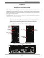
5-7 Serverboard Details ...................................................................................... 5-13
X9DAX-7F/iF Quick Reference ..................................................................... 5-13
5-8 Connector Denitions ................................................................................... 5-16
5-9 Jumper Settings ............................................................................................ 5-23
5-10 Onboard Indicators ........................................................................................ 5-26
5-11 SATA Ports .................................................................................................... 5-27
5-12 Installing Software ......................................................................................... 5-28
Supero Doctor III ........................................................................................... 5-29
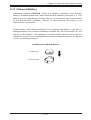
5-13 Onboard Battery ............................................................................................ 5-31
Chapter 6 Advanced Chassis Setup
6-1 Static-Sensitive Devices .................................................................................. 6-2
Precautions ..................................................................................................... 6-2
6-2 Control Panel .................................................................................................. 6-2
6-3 System Cooling ............................................................................................... 6-3
System Fan Failure ......................................................................................... 6-3
Replacing System Fans .................................................................................. 6-3
6-4 Power Supply .................................................................................................. 6-5
Power Supply Failure ...................................................................................... 6-5
Replacing the Power Supply ........................................................................... 6-5
Power Supply Connections ............................................................................. 6-6
6-5 Conguring the Storage Module .................................................................... 6-7
Tower or Rack Conguration........................................................................... 6-7
Rotating the Storage Module .......................................................................... 6-8
Installing Drives in the Storage Module .......................................................... 6-9
Removing a Drive Carrier ............................................................................. 6-10
Adding Peripheral Drives .............................................................................. 6-12
6-6 Installing Hard Drives in the Chassis ............................................................ 6-13
Chapter 7 BIOS
7-1 Introduction ...................................................................................................... 7-1
Starting BIOS Setup Utility .............................................................................. 7-1
How To Change the Conguration Data ......................................................... 7-2
Starting the Setup Utility ................................................................................. 7-2
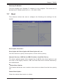
7-2 Main Setup ...................................................................................................... 7-2
SUPERSERVER 7047R-TXRF User's Manual

7-3 Advanced Setup Congurations...................................................................... 7-4
7-4 Overclocking ................................................................................................. 7-25
7-5 Event Logs .................................................................................................... 7-27
7-6 IPMI ............................................................................................................... 7-29
7-7 Boot ............................................................................................................... 7-31
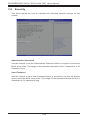
7-8 Security ......................................................................................................... 7-32
7-9 Save & Exit ................................................................................................... 7-33
Appendix A BIOS Error Beep Codes
Appendix B System Specications
Table of Contents
viii

Chapter 1
Introduction
1-1 Overview
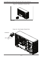
The SuperWorkstation 7047AX-TRF/7047AX-72RF is comprised of two main
subsystems: the CSE-747TG-R1K28B-SQ 4U/Tower chassis and the X9DAX-7F/iF
dual Intel Xeon processor serverboard. Please refer to our web site for information
on operating systems that have been certied for use with the system (www.
supermicro.com).
In addition to the serverboard and chassis, various hardware components have
been included with the workstation, as listed below:
•Two 80-mm exhaust fans (FAN-0082L4)
•Four 92 x 38 mm front fans (FAN-0114L4)
•SATA accessories:
One HD backplane (BPN-SAS-747TQ)
Eight 3.5" hard disk drive trays (MCP-220-00094-0B)
Three 5.25" drive trays (MCP-220-00073-0B)
•One SuperWorkstation 7047AX-TRF/7047AX-72RF Quick Reference Guide
Optional
•One 4U 17.2" width rack rail set (MCP-290-00059-0N)
•Two 4U active CPU heatsinks (SNK-P2050AP4)
Note: a complete list of safety warnings is provided on the Supermicro web site at
http://www.supermicro.com/about/policies/safety_information.cfm
Chapter 1: Introduction
1-1

1-2
SUPERSERVER 7047AX-TRF/7047AX-72RF User's Manual
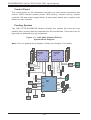
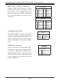
1-2 Serverboard Features
At the heart of the SuperWorkstation 7047AX-TRF/7047AX-72RF lies the X9DAX-
7F/iF, a dual processor serverboard based on the Intel C602 chipset. Below are
the main features of the X9DAX-7F/iF. (See Figure 1-1 for a block diagram of the
chipset).
Processors
The X9DAX-7F/iF supports two Intel
®
E5-2600 Series processors in LGA 2011
sockets (Socket R). Please refer to the serverboard description pages on our web
site for a complete listing of supported processors (www.supermicro.com).
Memory
The X9DAX-7F/iF has sixteen DIMM slots that can support up to 512 GB of
DDR3 Registered(RDIMM)/Load Reduced (LRDIMM) ECC or up to 128 GB of
Unbuffered(UDIMM) ECC/Non-ECC 1600/1333/1066/800 MHz 4-channel memory
modules. Modules of the same size and speed are recommended. See Chapter
5 for details.
SAS
A total of eight SAS 2.0 ports are provided with an LSI 2208 SAS controller. RAID
levels 0, 1, 5, 10, 50 and 60 are supported.
Note: The operating system you use must have RAID support to enable the hotswap
capability and RAID function of the SAS drives.
Serial ATA
A SATA controller is integrated into the chipset to provide a ten-port SATA subsystem,
which is RAID 0, 1, 5 and 10 supported. the I-SATA 0-5 ports are SATA 3.0 ports and
the S-SATA1-3 ports are SATA 2.0 ports. The SATA drives are hot-swappable units.
Note: The operating system you use must have RAID support to enable the hot-
swap capability and RAID function of the Serial ATA drives.
PCI Expansion Slots
The X9DAX-7F/iF has two PCI-E 3.0 x16, four PCI-E 3.0 x8 and one PCI-E 3.0 x4
(in x8) slots for a total of seven PCI expansion slots.

1-3
Chapter 1: Introduction
Rear I/O Ports
The color-coded I/O ports include one COM port, a VGA (monitor) port, two USB
3.0 ports, four USB 2.0 ports, a dedicated IPMI LAN port and two Gb Ethernet
LAN ports.
IPMI
IPMI (Intelligent Platform Management Interface) is a hardware-level interface
specication that provides remote access, monitoring and administration for
Supermicro workstation platforms. IPMI allows administrators to view a workstation’s
hardware status remotely, receive an alarm automatically if a failure occurs, and
power cycle a system that is non-responsive.
1-3 Chassis Features
The following is a general outline of the main features of the CSE-747TG-R1K28B-
SQ chassis.
System Power
The CSE-747TG-R1K28B-SQ chassis includes a 1280W high-efciency, redundant
(1+1) power supply consisting of two power supply modules. In the unlikely event
a power supply module fails, replacement is simple and can be done without tools.
The AC power cord should be removed from the system before servicing or replacing
a power supply module. See Chapter 6 for details.
Mounting Rails (optional)
The CSE-747TG-R1K28B-SQ can be placed in a rack for secure storage and use.
To setup your rack, follow the step-by-step instructions included in this manual in
Chapter 2.
Hard Drive/Drive Bays
The CSE-747TG-R1K28B-SQ chassis features eight drive bays for SATA drives.
These drives are hot -swappable. Once set up correctly, these drives can be
removed without powering down the workstation.
The CSE-747TG-R1K28B-SQ chassis also provides three 5.25” peripheral drive
bays for oppy drives, DVD-ROM/CD-ROM drives, or additional hard drives.

1-4
SUPERSERVER 7047AX-TRF/7047AX-72RF User's Manual
Control Panel
The control panel on the workstation provides you with system monitoring and
control. LEDs indicate system power, HDD activity, network activity, system
overheat, UID and power supply failure. A main power button and a system reset
button are also included.
Cooling System
The CSE-747TG-R1K28B-SQ chassis accepts four system fans and two rear
exhaust fans. System fans are powered from the serverboard. These fans are 4U
high and are powered by 4-pin connectors.
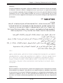
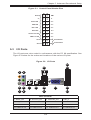
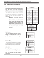
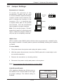
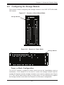
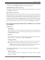
Figure 1-1. Intel C602 Chipset (PCH A):
System Block Diagram
Note: This is a general block diagram. Please see Chapter 5 for details.
#1-4
#1-3
#1-2
Intel E5-2600
8 SNB CORE
DDR3
#2 #1 #3
P0
P1
DMI2
LAN
X540
USB 3.0
(REAR)
COM1
internal
1394
SPI
BMC
WPCM450
VGA
USB 3.0
LANE1/2/3/4
LANE6
PCH
C602
LANE7
LANE8
PCI
#0~#3
#0~#3
#0~#7
SCU
DMI2
4 GB/s
DMI2
3.0 Gb/S
(FRONT)
SAS2208
PCI-E X16 G3
PCI-E X8 G3
PCI-E X4
PCI-E X8 G3
PCI-E X8 G3
PCI-E X16 G3
QPI
8G
Intel E5-2600
8 SNB CORE
DDR3
#3A #3B #2A #2B #1
SAS2
#1-1
DDR3
PCI-E X16
SLOT 2
PCI-E X8
SLOT 3
PCI-E X8 G3
PCI-E X8 G3
PCI-E X8 G3
PCI-E X8
SLOT 7
PCI-E X8
SLOT 5
PCI-E X8
SLOT 6
PCI-E X16
SLOT 1
PCI-E X4
SLOT 4
800/1066/1333
#0-4
#0-3
#0-2
#0-1
DDR3
800/1066/1333
QPI
8G
3.0 Gb/S
6.0 Gb/S
For Port 0/1
USB 2.0
4 Rear
2 Front
1 Type-A
PCI-E X1
PCI-E X1
PCI
P0
P1
SAS
Ports 0~3
SAS
Ports 4~7
SATA
SATA2
USB

1-5
Chapter 1: Introduction
1-5 Contacting Supermicro
Headquarters
Address: Super Micro Computer, Inc.
980 Rock Ave.
San Jose, CA 95131 U.S.A.
Tel: +1 (408) 503-8000
Fax: +1 (408) 503-8008
Email: [email protected] (General Information)
[email protected] (Technical Support)
Web Site: www.supermicro.com
Europe
Address: Super Micro Computer B.V.
Het Sterrenbeeld 28, 5215 ML
's-Hertogenbosch, The Netherlands
Tel: +31 (0) 73-6400390
Fax: +31 (0) 73-6416525
Email: [email protected] (General Information)
[email protected] (Technical Support)
[email protected] (Customer Support)
Asia-Pacic
Address: Super Micro Computer, Inc.
4F, No. 232-1, Liancheng Rd.
Chung-Ho Dist., New Taipei City 235
Taiwan
Tel: +886-(2) 8226-3990
Fax: +886-(2) 8226-3991
Web Site: www.supermicro.com.tw
Technical Support:
Email: [email protected]
Tel: +886-(2) 8226-5990

Chapter 2: Workstation Installation
2-1
Chapter 2
Workstation Installation
2-1 Overview
This chapter provides a quick setup checklist to get your SuperWorkstation 7047AX-
TRF/7047AX-72RF up and running. Following the steps in the order given should
enable you to have the system operational within a minimal amount of time. If
your system is not already fully integrated with a motherboard, processor, system
memory etc., please turn to the chapter or section noted in each step for details on
installing specic components.
2-2 Unpacking the System
You should inspect the box the SuperWorkstation 7047AX-TRF/7047AX-72RF was
shipped in and note if it was damaged in any way. If the workstation itself shows
damage, you should le a damage claim with the carrier who delivered it.
Decide on a suitable location for setting up and operating the SuperWorkstation
7047AX-TRF/7047AX-72RF. It should be situated in a clean, dust-free area that is
well ventilated. Avoid areas where heat, electrical noise and electromagnetic elds
are generated. You will also need it placed near a grounded power outlet.
Warnings and Precautions!
•Review the electrical and general safety precautions in Chapter 4.
• Use a regulating uninterruptible power supply (UPS) to protect the workstation
from power surges, voltage spikes and to keep your system operating in case
of a power failure.
•Allow the power supply units and Serial ATA drives to cool before touching
them.
•To maintain proper cooling, always keep all chassis panels closed when not
being serviced.

2-2
SUPERSERVER 7047AX-TRF/7047AX-72RF User's Manual
2-3 Preparing for Setup
The box your workstation was shipped in may include two sets of rail assemblies,
two rail mounting brackets and the mounting screws needed to install the system
into the rack (optional parts). Please read this section in its entirety before you begin
the installation procedure outlined in the sections that follow.
Choosing a Setup Location
•Leave enough clearance in front of the rack to enable you to open the front
door completely (~25 inches).
•Leave approximately 30 inches of clearance in the back of the rack to allow for
sufcient airow and ease in servicing.
•This product is for installation only in a Restricted Access Location (dedicated
equipment rooms, service closets and the like).
Rack Precautions
•Ensure that the leveling jacks on the bottom of the rack are fully extended to
the oor with the full weight of the rack resting on them.
•In single rack installation, stabilizers should be attached to the rack. In multiple
rack installations, the racks should be coupled together.
•Always make sure the rack is stable before extending a component from the
rack.
•You should extend only one component at a time - extending two or more si-
multaneously may cause the rack to become unstable.
•Rack-mounted equipment should not be used as a shelf or work space.
Workstation Precautions
•Review the electrical and general safety precautions in Chapter 4.
•Determine the placement of each component in the rack before you install the
rails.
Warnings and Precautions!

Chapter 2: Workstation Installation
2-3
•Install the heaviest workstation components on the bottom of the rack rst, and
then work up.
•Use a regulating uninterruptible power supply (UPS) to protect the workstation
from power surges, voltage spikes and to keep your system operating in case
of a power failure.
•Allow the hot plug SATA drives and power supply modules to cool before touch-
ing them.
•Always keep the rack's front door and all panels and components on the work-
stations closed when not servicing to maintain proper cooling.
Rack Mounting Considerations
Ambient Operating Temperature
If installed in a closed or multi-unit rack assembly, the ambient operating tempera-
ture of the rack environment may be greater than the ambient temperature of the
room. Therefore, consideration should be given to installing the equipment in an
environment compatible with the manufacturer’s maximum rated ambient tempera-
ture (Tmra).
Reduced Airow
Equipment should be mounted into a rack so that the amount of airow required
for safe operation is not compromised.
Mechanical Loading
Equipment should be mounted into a rack so that a hazardous condition does not
arise due to uneven mechanical loading.
Circuit Overloading
Consideration should be given to the connection of the equipment to the power
supply circuitry and the effect that any possible overloading of circuits might have
on overcurrent protection and power supply wiring. Appropriate consideration of
equipment nameplate ratings should be used when addressing this concern.

2-4
SUPERSERVER 7047AX-TRF/7047AX-72RF User's Manual
Reliable Ground
A reliable ground must be maintained at all times. To ensure this, the rack itself
should be grounded. Particular attention should be given to power supply connec-
tions other than the direct connections to the branch circuit (i.e. the use of power
strips, etc.).
Warning! To prevent bodily injury when mounting or servicing this unit in a
rack, you must take special precautions to ensure that the system remains
stable. The following guidelines are provided to ensure your safety:
•This unit should be mounted at the bottom of the rack if it is the only unit in
the rack.
•When mounting this unit in a partially lled rack, load the rack from the bottom
to the top with the heaviest component at the bottom of the rack.
•If the rack is provided with stabilizing devices, install the stabilizers before
mounting or servicing the unit in the rack.
2-4 Installing the Chassis onto a Rack
This section provides information on installing the SC747 chassis into a rack unit
with the optional 4U 17.2" width rail set (MCP-290-00059-0B). There are a variety
of rack units on the market, which may mean the assembly procedure will differ
slightly. You should also refer to the installation instructions that came with the rack
unit you are using.
Notes: The outer rail is adjustable from 26" to 38.25". The MCP-290-00059-0N rail
kit is an optional accessory.
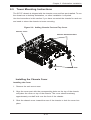
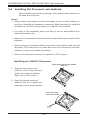
Removing the Chassis Cover and Feet
The SC747 chassis is shipped with the chassis cover and feet pre-installed. Both
the feet and cover must be removed for before installing the rails.
Removing the Chassis Top Cover
1. Locate the chassis cover lock (blue lever) at the rear of the chassis cover.
2. Slide the chassis cover lock to the right and push chassis cover forward.
3. Lift the chassis top cover off the chassis.

Chapter 2: Workstation Installation
2-5
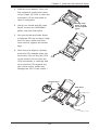
Removing the Chassis Feet
1. Place the chassis on its side with the chassis side cover facing upward.
2. Remove the screw holding the chassis foot in place.
3. The foot lock is a tab located in the center of the foot that prevents the foot
from sliding. Using a at head screwdriver, gently lift the foot lock upward
and slide the foot toward the rear of the chassis.
4. Repeat steps 2 and 3 with each remaining foot.
Identifying the Sections of the Rack Rails
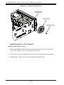
The chassis package includes two rack rail assemblies in the rack mounting kit.
Each assembly consists of two sections: an inner xed chassis rail that secures
directly to the workstation chassis and an outer xed rack rail that secures directly
to the rack itself.

2-6
SUPERSERVER 7047AX-TRF/7047AX-72RF User's Manual
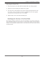
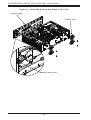
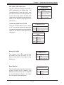
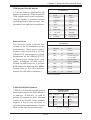
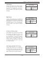
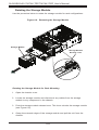
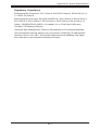
Figure 2-1. Removing the Feet and Chassis Top Cover
Chassis Cover
Chassis Feet
Chassis Cover Lock

Chapter 2: Workstation Installation
2-7
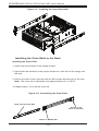
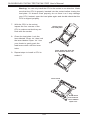
Figure 2-2. Identifying the Inner Rails and Chassis Handles
Chassis Handle
Inner Rails
Installing the Chassis Handles and Inner Rails
Installing the Inner Rails
1. Locate the chassis handles and handle screws.
2. Align the chassis handle with the front of the chassis and secure with the
three chassis handle screws.
3. Repeats steps 1 and 2 with the other handle.
4. Locate the inner rails and screws in the shipping package.
5. Align the inner rails against the chassis, as shown. Conrm that the rails are
ushed against the edge of the chassis.
6. Tighten the screws. Do not over-tighten.
7. Repeat steps 5 and 6 with the other inner rail.
Page is loading ...
Page is loading ...
Page is loading ...
Page is loading ...
Page is loading ...
Page is loading ...
Page is loading ...
Page is loading ...
Page is loading ...
Page is loading ...
Page is loading ...
Page is loading ...
Page is loading ...
Page is loading ...
Page is loading ...
Page is loading ...
Page is loading ...
Page is loading ...
Page is loading ...
Page is loading ...
Page is loading ...
Page is loading ...
Page is loading ...
Page is loading ...
Page is loading ...
Page is loading ...
Page is loading ...
Page is loading ...
Page is loading ...
Page is loading ...
Page is loading ...
Page is loading ...
Page is loading ...
Page is loading ...
Page is loading ...
Page is loading ...
Page is loading ...
Page is loading ...
Page is loading ...
Page is loading ...
Page is loading ...
Page is loading ...
Page is loading ...
Page is loading ...
Page is loading ...
Page is loading ...
Page is loading ...
Page is loading ...
Page is loading ...
Page is loading ...
Page is loading ...
Page is loading ...
Page is loading ...
Page is loading ...
Page is loading ...
Page is loading ...
Page is loading ...
Page is loading ...
Page is loading ...
Page is loading ...
Page is loading ...
Page is loading ...
Page is loading ...
Page is loading ...
Page is loading ...
Page is loading ...
Page is loading ...
Page is loading ...
Page is loading ...
Page is loading ...
Page is loading ...
Page is loading ...
Page is loading ...
Page is loading ...
Page is loading ...
Page is loading ...
Page is loading ...
Page is loading ...
Page is loading ...
Page is loading ...
Page is loading ...
Page is loading ...
Page is loading ...
Page is loading ...
Page is loading ...
Page is loading ...
Page is loading ...
Page is loading ...
Page is loading ...
Page is loading ...
Page is loading ...
Page is loading ...
Page is loading ...
Page is loading ...
Page is loading ...
Page is loading ...
Page is loading ...
Page is loading ...
Page is loading ...
Page is loading ...
Page is loading ...
Page is loading ...
Page is loading ...
Page is loading ...
Page is loading ...
Page is loading ...
Page is loading ...
Page is loading ...
Page is loading ...
Page is loading ...
Page is loading ...
Page is loading ...
Page is loading ...
Page is loading ...
Page is loading ...
-
 1
1
-
 2
2
-
 3
3
-
 4
4
-
 5
5
-
 6
6
-
 7
7
-
 8
8
-
 9
9
-
 10
10
-
 11
11
-
 12
12
-
 13
13
-
 14
14
-
 15
15
-
 16
16
-
 17
17
-
 18
18
-
 19
19
-
 20
20
-
 21
21
-
 22
22
-
 23
23
-
 24
24
-
 25
25
-
 26
26
-
 27
27
-
 28
28
-
 29
29
-
 30
30
-
 31
31
-
 32
32
-
 33
33
-
 34
34
-
 35
35
-
 36
36
-
 37
37
-
 38
38
-
 39
39
-
 40
40
-
 41
41
-
 42
42
-
 43
43
-
 44
44
-
 45
45
-
 46
46
-
 47
47
-
 48
48
-
 49
49
-
 50
50
-
 51
51
-
 52
52
-
 53
53
-
 54
54
-
 55
55
-
 56
56
-
 57
57
-
 58
58
-
 59
59
-
 60
60
-
 61
61
-
 62
62
-
 63
63
-
 64
64
-
 65
65
-
 66
66
-
 67
67
-
 68
68
-
 69
69
-
 70
70
-
 71
71
-
 72
72
-
 73
73
-
 74
74
-
 75
75
-
 76
76
-
 77
77
-
 78
78
-
 79
79
-
 80
80
-
 81
81
-
 82
82
-
 83
83
-
 84
84
-
 85
85
-
 86
86
-
 87
87
-
 88
88
-
 89
89
-
 90
90
-
 91
91
-
 92
92
-
 93
93
-
 94
94
-
 95
95
-
 96
96
-
 97
97
-
 98
98
-
 99
99
-
 100
100
-
 101
101
-
 102
102
-
 103
103
-
 104
104
-
 105
105
-
 106
106
-
 107
107
-
 108
108
-
 109
109
-
 110
110
-
 111
111
-
 112
112
-
 113
113
-
 114
114
-
 115
115
-
 116
116
-
 117
117
-
 118
118
-
 119
119
-
 120
120
-
 121
121
-
 122
122
-
 123
123
-
 124
124
-
 125
125
-
 126
126
-
 127
127
-
 128
128
-
 129
129
-
 130
130
-
 131
131
-
 132
132
-
 133
133
-
 134
134
-
 135
135


Supermicro 7047AX-72RF User manual
- Category
- Server barebones
- Type
- User manual
- This manual is also suitable for
Ask a question and I''ll find the answer in the document
Finding information in a document is now easier with AI
Related papers
-
Supermicro SC846X User manual
-
-
-
-
-
-
-
-
-
Other documents
-
 Supero SC835BTQ-R1K28B User manual
-
Gigabyte GA-7TEWH1 User manual
-
Acer Altos T110 F4 User manual
-
 Supero SUPERSERVER8027R-TRF+/7RFT+ User manual
-
ZyXEL UNS2700 Installation guide
-
 Supero SuperWorkstation 5035G-T User manual
-
 JAR SYSTEMS jar-systems CS-1610 USB-C Charging Hub Installation guide
-
SUPER MICRO Computer SUPERSERVER 6015B-T User manual
-
-


