Page is loading ...

®
SuperServer
1018L-Mp
SUPER
uSer’S MANuAL
Revision1.0

ii
The information in this User’s Manual has been carefully reviewed and is believed to be accurate.
The vendor assumes no responsibility for any inaccuracies that may be contained in this document,
makes no commitment to update or to keep current the information in this manual, or to notify any
person or organization of the updates. Please Note: For the most up-to-date version of this
manual, please see our web site at www.supermicro.com.
Super Micro Computer, Inc. ("Supermicro") reserves the right to make changes to the product
described in this manual at any time and without notice. This product, including software and
documentation, is the property of Supermicro and/or its licensors, and is supplied only under a
license. Any use or reproduction of this product is not allowed, except as expressly permitted by
the terms of said license.
IN NO EVENT WILL SUPERMICRO BE LIABLE FOR DIRECT, INDIRECT, SPECIAL, INCIDENTAL,
SPECULATIVE OR CONSEQUENTIAL DAMAGES ARISING FROM THE USE OR INABILITY TO
USE THIS PRODUCT OR DOCUMENTATION, EVEN IF ADVISED OF THE POSSIBILITY OF
SUCH DAMAGES. IN PARTICULAR, SUPERMICRO SHALL NOT HAVE LIABILITY FOR ANY
HARDWARE, SOFTWARE, OR DATA STORED OR USED WITH THE PRODUCT, INCLUDING THE
COSTS OF REPAIRING, REPLACING, INTEGRATING, INSTALLING OR RECOVERING SUCH
HARDWARE, SOFTWARE, OR DATA.
Any disputes arising between manufacturer and customer shall be governed by the laws of Santa
Clara County in the State of California, USA. The State of California, County of Santa Clara shall
be the exclusive venue for the resolution of any such disputes. Super Micro's total liability for all
claims will not exceed the price paid for the hardware product.
FCC Statement: This equipment has been tested and found to comply with the limits for a Class
A digital device pursuant to Part 15 of the FCC Rules. These limits are designed to provide
reasonable protection against harmful interference when the equipment is operated in a commercial
environment. This equipment generates, uses, and can radiate radio frequency energy and, if not
installed and used in accordance with the manufacturer’s instruction manual, may cause harmful
interference with radio communications. Operation of this equipment in a residential area is likely
to cause harmful interference, in which case you will be required to correct the interference at your
own expense.
California Best Management Practices Regulations for Perchlorate Materials: This Perchlorate
warning applies only to products containing CR (Manganese Dioxide) Lithium coin cells. “Perchlorate
Material-special handling may apply. See www.dtsc.ca.gov/hazardouswaste/perchlorate”
WARNING: Handling of lead solder materials used in this
product may expose you to lead, a chemical known to
the State of California to cause birth defects and other
reproductive harm.
Manual Revision 1.0
Release Date: June 18, 2014
Unless you request and receive written permission from Super Micro Computer, Inc., you may not
copy any part of this document.
Information in this document is subject to change without notice. Other products and companies
referred to herein are trademarks or registered trademarks of their respective companies or mark
holders.
Copyright © 2014 by Super Micro Computer, Inc.
All rights reserved.
Printed in the United States of America

Preface
iii
Preface
About This Manual
This manual is written for professional system integrators and PC technicians.
It provides information for the installation and use of the server. Installation and
maintainance should be performed by experienced technicians only.
Please refer to the server specications page on our Web site for updates on
supported memory, processors and operating systems (http://www.supermicro.
com).

SuperServer 1018L-MP User's Guide
iv
Contents
Chapter 1 Introduction ..............................................................................1-1
1-1 Overview ......................................................................................................... 1-1
1-2 Motherboard Features ..................................................................................... 1-1
Processors ...................................................................................................... 1-1
Memory ........................................................................................................... 1-1
Serial ATA ........................................................................................................ 1-2
PCI Expansion Slots ....................................................................................... 1-2
Rear I/O Ports ................................................................................................. 1-2
1-3 Server Chassis Features ................................................................................ 1-2
System Power ................................................................................................. 1-2
Hard Disk Drive .............................................................................................. 1-2
Front Panel Control ........................................................................................ 1-2
Cooling ............................................................................................................ 1-2
1-4 Contacting Supermicro .................................................................................... 1-4
Chapter 2 Server Installation ...................................................................2-1
2-1 Overview ......................................................................................................... 2-1
2-2 Unpacking the System .................................................................................... 2-1
2-3 Warnings and Precautions .............................................................................. 2-1
Chapter 3 System Interface ......................................................................3-1
3-1 Control Panel Buttons ..................................................................................... 3-1
Power .............................................................................................................. 3-1
Chapter 4 Standardized Warning Statements for AC Systems ............4-1
About Standardized Warning Statements ....................................................... 4-1
Warning Denition ........................................................................................... 4-1
Installation Instructions .................................................................................... 4-4
Circuit Breaker ................................................................................................ 4-5
Power Disconnection Warning ........................................................................ 4-6
Equipment Installation ..................................................................................... 4-8
Restricted Area ................................................................................................ 4-9
Battery Handling ............................................................................................ 4-10
Redundant Power Supplies .......................................................................... 4-12
Backplane Voltage (if applicable to your system) ......................................... 4-13
Comply with Local and National Electrical Codes ........................................ 4-14
Product Disposal ........................................................................................... 4-15
Hot Swap Fan Warning (if applicable to your system) ................................. 4-16
Power Cable and AC Adapter ...................................................................... 4-18

Contents
v
Chapter 5 Advanced Motherboard Setup ...............................................5-1
5-1 Handling the Motherboard .............................................................................. 5-1
Precautions ..................................................................................................... 5-1
Unpacking ....................................................................................................... 5-1
5-2 Processor Installation ...................................................................................... 5-2
5-3 CPU Heatsink Installation ............................................................................... 5-4
5-4 Installing Memory ............................................................................................ 5-6
Memory Support .............................................................................................. 5-6
5-5 Connecting Cables .......................................................................................... 5-8
Connecting Data Cables ................................................................................. 5-8
Connecting Power Cables .............................................................................. 5-8
Connecting the Power Button ......................................................................... 5-8
5-6 Rear I/O Ports ................................................................................................. 5-9
5-7 Motherboard Details ...................................................................................... 5-10
5-8 Connector Denitions .................................................................................... 5-12
Power Button (JF1) ....................................................................................... 5-14
5-9 Jumper Settings ............................................................................................ 5-19
Explanation of Jumpers ................................................................................ 5-19
CMOS Clear .................................................................................................. 5-19
5-10 Onboard Indicators ........................................................................................ 5-22
5-11 Serial ATA and HDD Connections ................................................................. 5-23
5-12 Installing Software ......................................................................................... 5-24
SuperDoctor III .............................................................................................. 5-25
5-13 Onboard Battery ............................................................................................ 5-27
Chapter 6 Advanced Chassis Setup ........................................................6-1
6-1 Removing the Power Cord .............................................................................. 6-1
6-2 Installing Mounting Brackets ........................................................................... 6-2
6-3 Removing the Chassis Cover ......................................................................... 6-3
6-4 Installing the Hard Drive ................................................................................ 6-4
6-6 Installing the Motherboard .............................................................................. 6-5
6-7 Replacing the System Fan .............................................................................. 6-7
Chapter 7 BIOS .........................................................................................7-1
7-1 Introduction ...................................................................................................... 7-1
Starting BIOS Setup Utility .............................................................................. 7-1
How To Change the Conguration Data ......................................................... 7-1
How to Start the Setup Utility ......................................................................... 7-2
7-2 Main Setup ...................................................................................................... 7-2
7-3 Advanced Setup Congurations...................................................................... 7-4

SuperServer 1018L-MP User's Guide
vi
7-4 Event Logs .................................................................................................... 7-25
7-5 Boot Settings ................................................................................................. 7-26
7-6 Security Settings ........................................................................................... 7-28
7-7 Save & Exit ................................................................................................... 7-29
Appendix A POST Error Beep Codes ..................................................... A-1
Recoverable POST Error Beep Codes ...........................................................A-1
Appendix B System Specications ........................................................ B-1

Chapter 1
Introduction
1-1 Overview
The SuperServer 1018L-MP is a compact, embedded system comprised of the
SC101i chassis and the X10SLV single processor motherboard. Refer to our web
site for information on operating systems that have been certied for use with the
system (www.supermicro.com).
For your system to work properly, please follow the links below to download all
necessary drivers and utilities, and the user’s manual for your server.
•Supermicro product manuals: http://www.supermicro.com/support/manuals/
•Product drivers and utilities: ftp://ftp.supermicro.com
•Product safety info: http://super-dev/about/policies/safety_information.cfm
If you have any questions, please contact our support team at:
This manual may be periodically updated without notice. Please check the
Supermicro Web site for possible updates to the manual revision level.
1-2 Motherboard Features
The server is built around the X10SLV, a single processor motherboard based on
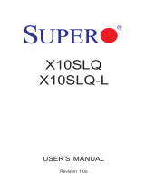
the Intel H81 chipset. Below are the main features. Figure 1-1 is a block diagram
of the chipset.
Processors
The X10SLV supports a single 4th Generation Intel Core i7, i5, i3, Pentium/Celeron
processor. Refer to the web site for a complete listing of supported processors
(www.supermicro.com).
Memory
The board has two DIMM slots that can support up to 16GB of Non-ECC DDR3
SODIMM up to 1600MHz memory. See Chapter 5 for details.
Chapter 1: Introduction
1-1

1-2
SUPERSERVER 1018L-MP User's Manual
Serial ATA
A SATA controller is also integrated into the chipset to provide two SATA 3.0 (mSATA)
and two SATA 2.0 ports.
PCI Expansion Slots
The system has one mini PCIe slot, full and half card with mSATA support.
Rear I/O Ports
The color-coded I/O ports include:
One DVI-I One HDMI
One DP Two GbE LAN
Two USB 3.0 Two USB 2.0
Two COM One Audio
1-3 Server Chassis Features
The SC101i is an mini-ITX form factor chassis. The following the main features.
System Power
Power is supplied through an 80W power adapter, plugged into a standard 110V
AC power outlet.
Hard Disk Drive
One 2.5" internal drive is supported by the system. This drive is not hot-swappable.
Front Panel Control
The front panel of the chassis includes a main power button with LED status
indicators.
Cooling
The chassis includes one 6cm fan.

1-3
Chapter 1: Introduction
Figure 1-1. System Block Diagram
Note: This is a general block diagram. Please see Chapter 5 for details.
1600/1333/1066MHz
2 X USB 3.0 Rear
5Gbps
USB3.0
VRD12.5
INTEL LGA1150
PCIe x16 SLOT
PCIe2.0_x16
5.0GT/s
SVID
VRM 12.5
DDR3 (CHA)
DIMMA1
DDR3 (CHB)
DIMMB1
1600/1333/1066MHz
5GT/s
x4 DMI
Shared with mSATA
SATA-III (X10SLV-Q)
2 X USB 2.0 REAR
6Gb/s
480Mbps
USB2.0
2 X SATA-III
SATA-III
RJ45
2.5GT/s
PCIe2.0_x1 GLAN1
I217V
PCH
Intel
H81 / Q87
(Socket-H3)
2.7 Gb/s
x2 FDI
AZALIA
Realtek ALC888S-VD2
RJ45
2.5GT/s
PCIe2.0_x1 GLAN2
I210-AT
Mini PCI-E SLOT
PCIe2.0_x1
5GT/s
BLOCK DIAGRAM
RoHS 6/6
FLASH
SPI 128Mb
SPI
Display Port
HDMI
DVI-I
Digital port B
Digital port C
Digital port D
TPM1.2 Header
LPC
HWM
COM1/2 Rear
NCT6106D
LPC I/O
SODIMM
X10SLV / X10SLV-Q
PCIE[3]
PCIE[4]
PCIE[2]
SATA[0/1]
SATA[0]
SATA-II
3Gb/s
SATA[4/5]
Note: I-SATA0 Function disabled whe m-SATA inserted .
DDI B
DDI C
DDI D
RGB
USB[0/1]
USB[2/3]
2 X USB 2.0 Front
480Mbps
USB2.0
USB[4/5]
6Gb/s
COM 3/4/5 Header
1 X USB A-type
480Mbps
USB2.0
USB[10]
Note: COM5 support RS485
/422
GPIO
Expander
USB[11]
3x audio jack
Express
2 X SATA-III
(X10SLV-Q)
2 X SATA-II
(X10SLV)
(X10SLV Only)
PCIe3.0_x16
8.0GT/s
(X10SLV-Q)
(X10SLV)

1-4
SUPERSERVER 1018L-MP User's Manual
1-4 Contacting Supermicro
Headquarters
Address: Super Micro Computer, Inc.
980 Rock Ave.
San Jose, CA 95131 U.S.A.
Tel: +1 (408) 503-8000
Fax: +1 (408) 503-8008
Email: [email protected] (General Information)
[email protected] (Technical Support)
Web Site: www.supermicro.com
Europe
Address: Super Micro Computer B.V.
Het Sterrenbeeld 28, 5215 ML
's-Hertogenbosch, The Netherlands
Tel: +31 (0) 73-6400390
Fax: +31 (0) 73-6416525
Email: [email protected] (General Information)
[email protected] (Technical Support)
[email protected] (Customer Support)
Web Site: www.supermicro.nl
Asia-Pacic
Address: Super Micro Computer, Inc.
3F, No. 150, Jian 1st Rd.
Zhonghe Dist., New Taipei City 235
Taiwan (R.O.C)
Tel: +886-(2) 8226-3990
Fax: +886-(2) 8226-3992
Email: [email protected]
Web Site: www.supermicro.com.tw

Chapter 2: Server Installation
2-1
Chapter 2
Server Installation
2-1 Overview
If your system is not already fully integrated with processors and system memory
refer to later chapters for details on installing specic components.
2-2 Unpacking the System
You should inspect the box in which the system was shipped and note if it was
damaged in any way. If the server itself shows damage you should le a damage
claim with the carrier who delivered it.
Decide on a suitable location for the server. It should be situated in a clean,
dust-free area that is well ventilated. Avoid areas where heat, electrical noise and
electromagnetic elds are generated. You will also need it placed near a grounded
power outlet.
2-3 Warnings and Precautions
•This product is not suitable for use with visual display work place devices
acccording to §2 of the the German Ordinance for Work with Visual Display Units.
•Review the electrical and general safety precautions in Chapter 4.
•Use a regulating uninterruptible power supply (UPS) to protect the server from
power surges, voltage spikes and to keep your system operating in case of a
power failure.

2-2
SUPERSERVER 1018L-MP User's Manual
Notes

Chapter 3: System Interface
3-1
Chapter 3
System Interface
3-1 Control Panel Buttons
The SC101i chassis includes one power on/off push-button on the front of the
chassis.
Power
The main power button is used to apply or remove power from the power supply
to the server system. Turning off system power with this button removes the main
power but keeps standby power supplied to the system. Therefore, you must unplug
the system before servicing.
This button features an LED that indicates hard drive activity as follows:
•Blue – Power on
•White – HDD activity
Figure 3-1. Power Button and Hard Drive Activity LED
Power Button

SUPERSERVER 1018L-MP User's Manual
3-2
Notes

4-1
Chapter 4: Warning Statements for AC Systems
Chapter 4
Standardized Warning Statements for AC Systems
About Standardized Warning Statements
The following statements are industry standard warnings, provided to warn the user
of situations which have the potential for bodily injury. Should you have questions
or experience difficulty, contact Supermicro's Technical Support department
for assistance. Only certied technicians should attempt to install or congure
components.
Read this appendix in its entirety before installing or conguring components in the
Supermicro chassis. Some warnings may not apply for your system.
These warnings may also be found on our web site at http://www.supermicro.com/
about/policies/safety_information.cfm.
Warning!
This warning symbol means danger. You are in a situation that could cause bodily
injury. Before you work on any equipment, be aware of the hazards involved with
electrical circuitry and be familiar with standard practices for preventing accidents.
Warning Denition
警告の定義
この警 告サインは危険を意 味します。
人身事故につながる可能性がありますので、いずれの機器でも動作させる前に、
電気回路に含まれる危険性に注意して、標準的な事故防止策に精通して下さい。
此警告符号代表危险。
您正处于可能受到严重伤害的工作环境中。在您使用设备开始工作之前,必须充分
意识到触电的危险,并熟练掌握防止事故发生的标准工作程序。请根据每项警告结
尾的声明号码找到此设备的安全性警告说明的翻译文本。
此警告符號代表危險。
您正處於可能身體可能會受損傷的工作環境中。在您使用任何設備之前,請注意觸
電的危險,並且要熟悉預防事故發生的標準工作程序。請依照每一注意事項後的號
碼找到相關的翻譯說明內容。

4-2
SUPERSERVER 1018L-MP User's Manual
Warnung
WICHTIGE SICHERHEITSHINWEISE
Dieses Warnsymbol bedeutet Gefahr. Sie benden sich in einer Situation, die zu
Verletzungen führen kann. Machen Sie sich vor der Arbeit mit Geräten mit den
Gefahren elektrischer Schaltungen und den üblichen Verfahren zur Vorbeugung
vor Unfällen vertraut. Suchen Sie mit der am Ende jeder Warnung angegebenen
Anweisungsnummer nach der jeweiligen Übersetzung in den übersetzten
Sicherheitshinweisen, die zusammen mit diesem Gerät ausgeliefert wurden.
BEWAHREN SIE DIESE HINWEISE GUT AUF.
INSTRUCCIONES IMPORTANTES DE SEGURIDAD
Este símbolo de aviso indica peligro. Existe riesgo para su integridad física. Antes
de manipular cualquier equipo, considere los riesgos de la corriente eléctrica y
familiarícese con los procedimientos estándar de prevención de accidentes. Al
nal de cada advertencia encontrará el número que le ayudará a encontrar el texto
traducido en el apartado de traducciones que acompaña a este dispositivo.
GUARDE ESTAS INSTRUCCIONES.
IMPORTANTES INFORMATIONS DE SÉCURITÉ
Ce symbole d'avertissement indique un danger. Vous vous trouvez dans une
situation pouvant entraîner des blessures ou des dommages corporels. Avant
de travailler sur un équipement, soyez conscient des dangers liés aux circuits
électriques et familiarisez-vous avec les procédures couramment utilisées pour
éviter les accidents. Pour prendre connaissance des traductions des avertissements
gurant dans les consignes de sécurité traduites qui accompagnent cet appareil,
référez-vous au numéro de l'instruction situé à la n de chaque avertissement.
CONSERVEZ CES INFORMATIONS.
ןונקת תורהצהאהרהז
ןה תואבה תורהצהא ינפמ שמתשמה תא ריהזהל תנמ לע ,היישעתה ינקת יפ לע תורהז הלבח
ה וא תולאש שיו הדימב .תירשפא תיזיפי ,יהשלכ היעבב תולקתרוציל שי הכימת תקלחמ םע רשק
רידגהל וא ןיקתהל םיאשר דבלב םיכמסומ םיאנכט .ורקימרפוס לש תינכט תאה .םיביכר
אורקל שי .ורקימרפוס יזראמב םיביכרה תרדגה וא תנקתה ינפל ואולמב חפסנה תא

4-3
Chapter 4: Warning Statements for AC Systems
4-3
안전을 위한 주의사항
경고!
이 경고 기호는 위험이 있음을 알려 줍니다. 작업자의 신체에 부상을 야기 할 수
있는 상태에 있게 됩니다. 모든 장비에 대한 작업을 수행하기 전에 전기회로와
관련된 위험요소들을 확인하시고 사전에 사고를 방지할 수 있도록 표준
작업절차를 준수해 주시기 바랍니다.
해당 번역문을 찾기 위해 각 경고의 마지막 부분에 제공된 경고문 번호를
참조하십시오
BELANGRIJKE VEILIGHEIDSINSTRUCTIES
Dit waarschuwings symbool betekent gevaar. U verkeert in een situatie die
lichamelijk letsel kan veroorzaken. Voordat u aan enige apparatuur gaat werken,
dient u zich bewust te zijn van de bij een elektrische installatie betrokken risico's
en dient u op de hoogte te zijn van de standaard procedures om ongelukken te
voorkomen. Gebruik de nummers aan het eind van elke waarschuwing om deze te
herleiden naar de desbetreffende locatie.
BEWAAR DEZE INSTRUCTIES
. !

4-4
SUPERSERVER 1018L-MP User's Manual
Installation Instructions
Warning!
Read the installation instructions before connecting the system to the power source.
Warnung
Vor dem Anschließen des Systems an die Stromquelle die Installationsanweisungen
lesen.
¡Advertencia!
Lea las instrucciones de instalación antes de conectar el sistema a la red de
alimentación.
Attention
Avant de brancher le système sur la source d'alimentation, consulter les directives
d'installation.
設置手順書
システムを電源に接続する前に、設置手順書をお読み下さい。
אורקל שי רוקמל תכרעמה רוביח ינפל הנקתה תוארוה תאחתמ.
시스템을 전원에 연결하기 전에 설치 안내를 읽어주십시오.
Waarschuwing
Raadpleeg de installatie-instructies voordat u het systeem op de voedingsbron
aansluit.
警告
将此系统连接电源前,请先阅读安装说明。
警告
將系統與電源連接前,請先閱讀安裝說明。

4-5
Chapter 4: Warning Statements for AC Systems
Circuit Breaker
Warning!
This product relies on the building's installation for short-circuit (overcurrent)
protection. Ensure that the protective device is rated not greater than: 250 V, 20 A.
サーキット・ブレーカー
この製品は、短絡(過電流)保護装置がある建物での設置を前提としています。
保護装置の定格が250 V、20 Aを超えないことを確認下さい。
Warnung
Dieses Produkt ist darauf angewiesen, dass im Gebäude ein Kurzschluss-
bzw. Überstromschutz installiert ist. Stellen Sie sicher, dass der Nennwert der
Schutzvorrichtung nicht mehr als: 250 V, 20 A beträgt.
¡Advertencia!
Este equipo utiliza el sistema de protección contra cortocircuitos (o sobrecorrientes)
del edicio. Asegúrese de que el dispositivo de protección no sea superior a: 250
V, 20 A.
Attention
Pour ce qui est de la protection contre les courts-circuits (surtension), ce produit
dépend de l'installation électrique du local. Vériez que le courant nominal du
dispositif de protection n'est pas supérieur à :250 V, 20 A.
לע ךמתסמ הז רצומנגהה תעינמל םינבמב תנקתומה יכ אדוול שי .ילמשח רצק
רצקה ינפמ ןגמה רישכמה ילמשחהמ רתוי אל אוה-250 V, 20 A
20A, 250V :
警告
此产品的短路(过载电流)保护由建筑物的供电系统提供,确保短路保护设备的额定电
流不大于250V,20A。
警告
此產品的短路(過載電流)保護由建築物的供電系統提供,確保短路保護設備的額定電
流不大於250V,20A。

4-6
SUPERSERVER 1018L-MP User's Manual
Power Disconnection Warning
電源切断の警告
システムコンポーネントの取り付けまたは取り外しのために、シャーシー内部にアクセス
するには、
システムの電源はすべてのソースから切断され、電源コードは電源モジュールから取り
外す必要があります。
警告
在你打开机箱并安装或移除内部器件前,必须将系统完全断电,并移除电源线。
警告
在您打開機殼安裝或移除內部元件前,必須將系統完全斷電,並移除電源線。
Warnung
Das System muss von allen Quellen der Energie und vom Netzanschlusskabel
getrennt sein, das von den Spg.Versorgungsteilmodulen entfernt wird, bevor es
auf den Chassisinnenraum zurückgreift, um Systemsbestandteile anzubringen oder
zu entfernen.
Warning!
The system must be disconnected from all sources of power and the power cord
removed from the power supply module(s) before accessing the chassis interior to
install or remove system components.
경고!
이 제품은 전원의 단락(과전류)방지에 대해서 전적으로 건물의 관련 설비에
의존합니다. 보호장치의 정격이 반드시 250V(볼트), 20A(암페어)를 초과하지
않도록 해야 합니다.
Waarschuwing
Dit product is afhankelijk van de kortsluitbeveiliging (overspanning) van
uw electrische installatie. Controleer of het beveiligde aparaat niet groter
gedimensioneerd is dan 220V, 20A.
/