Page is loading ...

GMI 10
quick start manual

2 GMI 10 Quick Start Manual
Introduction
The GMI 10 allows you to quickly
view important information about
your boat provided by connected
sensors.
Connected sensors transmit data to
the GMI 10 using NMEA 0183 or
NMEA 2000.
To install your GMI 10, use the
included installation instructions.
For a list of compatible sensors and
for more information about NMEA
2000, visit www.garmin.com.
The GMI 10 is
NMEA 2000
certied.
Manual Conventions
In this manual, when you are
instructed to select an item, use the
soft keys ( ) along the bottom
of the screen to select each item.
Small arrows (>) in the text indicate
that you should select each item
in order. For example, if you see
“select Menu > Setup,” you should
press the soft key under Menu,
Then use the soft keys to select
Setup.
Instrument Screen—the main
screen of the GMI 10. An
instrument screen displays data
provided by a sensor.
Menu Screens—screens used to
dene options.
GMI 10 Quick Start Manual 3
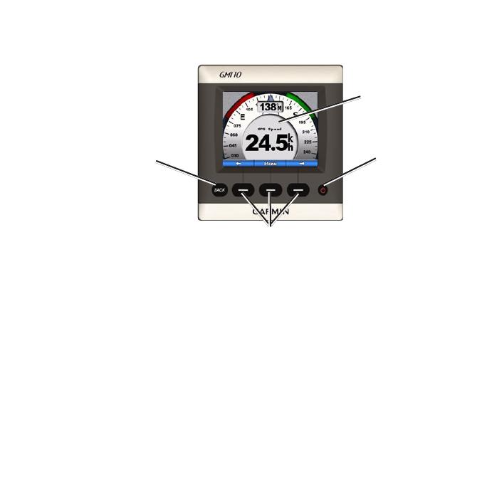
Unit Overview
Back
Power
Soft keys
Instrument
screen
Power—press and hold to power the unit on and off. Press and quickly
release to adjust display settings (page 12).
Soft Keys—used to navigate the menus and select items on the GMI 10.
Typically, the left and right soft keys cycle data on the instrument screen and
navigate menu screens, and the center soft key selects highlighted items and
opens the Menu.
Back—used to move back one menu screen. Press and hold to move all the
way back to the instrument screen from any menu screen.

4 GMI 10 Quick Start Manual
Using the GMI 10
Use the GMI 10 to view numerical
data provided by connected
sensors. Many data types can also
be displayed as an analog gauge
(page 6).
The types of data available
are determined by the sensors
connected to the GMI 10 either
through NMEA 2000 or NMEA
0183.
For example, when connected
to a GPS antenna such as a
GPS 17x, the GMI 10 can show
GPS position, course over ground,
speed over ground, average speed,
maximum speed obtained, and
distance traveled (trip odometer)
information.
Viewing Information
Instrument screens are organized by
category. The categories available
are:
Surface—speed, heading, odometer
(requires a GPS antenna or other
sensor that measures speed or
heading).
Water—depth and temperature
(requires a sonar device such as an
intelligent transducer).
Fuel—level, rate, range, economy
(requires a fuel sensor such as the
GFS 10). You must also have a
sensor that provides speed to use
range and economy information.
GMI 10 Quick Start Manual 5
Custom—create custom instrument
screens. Choose the number
and type of data elds on each
custom screen. You can create and
cycle through up to ve custom
instrument screens. (Page 7)
Selecting an Instrument
Screen Category
Change the instrument screen to a
different category from the menu:
1. From the instrument screen,
select Menu> Setup > Set
Instrument Type.
2. Choose the category you want to
view.
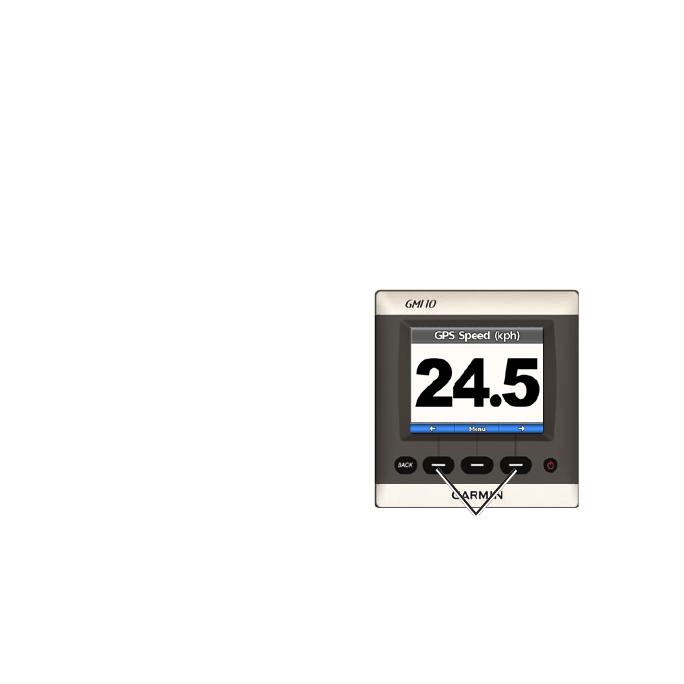
Cycling Through
Instrument Screens in a
Category
When viewing a category, use
the soft keys under the left and
right arrows to cycle through the
instrument screens available in that
category.
Cycle through instrument screens

6 GMI 10 Quick Start Manual
Changing Instrument
Screen Options
Data provided on an instrument
screen is represented either
numerically or as an analog gauge.
In many cases, a numerical value
can be shown as an analog gauge,
and vice versa.
To change the appearance of
an instrument screen:
From the instrument screen,
select Menu > Show Gauge to
view a gauge or Menu > Show
Number to show a number.
NOTE: If the instrument
screen can only be displayed
as a numeric value or an
analog gauge, this choice
will not be available. For
custom instrument screens,
see page 8.
Some instrument screens have
additional options available.
To change additional options
on an instrument screen:
From the instrument screen,
select Menu.
To change the source sensor,
select Source, and choose
sensor you want to use.
For example, if you have a
GPS antenna and a heading
sensor, choose the sensor
you prefer.
To change additional
options, such as resetting an
odometer, adding Trip Speed
Graphics to a speed gauge,
viewing a water-temperature
graph, or adding fuel, select
the option you want to
change.
•
•
GMI 10 Quick Start Manual 7
Creating a Custom
Instrument Screen
You can create and cycle through up
to ve custom instrument screens.
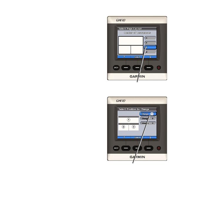
To create the rst custom
instrument screen:
1. From the instrument screen,
select Menu> Setup > Set
Instrument Type > Custom.
2. Selectthenumberofeldsyou
want to show on the custom
instrument screen (1–4).
3. Select the data type you would
liketoshowineacheld.For
a list of all data types, see
pages 14–17.
Select the number of elds
Select the data for each eld

8 GMI 10 Quick Start Manual
To add additional custom
instrument screens:
1. From the custom instrument
screen, select Menu > Add
Custom Page. (If you have
more than one custom
instrument screen, this option
will appear as Add/Remove
Custom Page.)
2. Selectthenumberofeldsyou
want to show on the custom
instrument screen.
3. Select the data type you would
liketoshowineacheld.For
a list of all data types, see
pages 14–17.
NOTE: You can create up
to ve custom instrument
screens and cycle through
them (page 5).
To change an existing custom
instrument screen:
1. From the custom instrument
screen you want to change,
select Menu > Change
Appearance.
Select Change Page Layout
to change the number of
eldsanddatatypesinthe
elds.
Select Change Data Style
to switch between numerical
and analog displays.
2. Select Done whennished.
To remove an existing custom
instrument screen:
From the custom instrument
screen you want to remove,
select Menu > Add/Remove
Custom Page. > Remove
Custom Page.
•
•

GMI 10 Quick Start Manual 9
Conguring the
GMI 10
You can congure various options
on the GMI 10.
From the instrument screen, select
Menu > Setup.
System—customize various system
options (page 9).
Alarms—set alarms to sound for
specic occurrences (page 11).
Display—change the options for
backlight, color mode, and screen
sharing (page 12).
NMEA 2000 Devices—manage
options for connected NMEA 2000
devices (page 13).
Customizing System
Options
To customize system options on
the GMI 10, from the instrument
screen, select Menu > Setup >
System.
Units—Select Statute (mh, ft, ºF),
Metric (kh, m, ºC), or Nautical
(kt, ft, ºF) to dene the individual
units of measure as a group. Select
Custom to individually dene units
of measure.
Heading—set the reference used in
calculating heading information.
Auto Mag Var—Automatic
Magnetic Variation automatically
sets the magnetic declination for
your acquired GPS position.
•

10 GMI 10 Quick Start Manual
True—sets true north as the
heading reference.
User Mag Var—allows you to
set the magnetic variation value.
Beeper—set when the GMI 10
makes audible sounds.
Auto Power—select if the unit
powers on with the NMEA 2000
network.
Language—select the on-screen
language.
Operating Mode—set the GMI 10
for normal operation or for a store
demonstration.
Position—specify how the GMI 10
handles coordinates and maps.
Position Format—change the
coordinate style in which a given
•
•
•
location reading appears.
Map Datum—change the
coordinate system in which the
map is structured.
CAUTION: Do not change
the position format or map
datum unless you are using a
map or chart that species a
different position format or
map datum.
Time—specify how the GMI 10
handles time information.
Time Format—select a 12 hour,
24 hour, or UTC time format.
Time Zone—set the time
zone you want to use for time
readings.
•
•
•

GMI 10 Quick Start Manual 11
DST (Daylight Saving Time)—
indicate whether you want
daylight saving time Off, On,
or Auto. The auto setting turns
daylight saving time on or off,
depending on the time of year.
Speed Sources—select what sensor
to use when determining Fuel
Economy and Wind speed.
GPS Skyview—view GPS
satellites.
System Information—view unit
software information.
Factory Defaults—reset the unit to
factory defaults.
•
Setting Alarms
To set alarms on the GMI 10, from
the instrument screen, select Menu
> Setup > Alarms.
Shallow Water—set an alarm to
sound when the depth is less than
the specied value.
Deep Water—set an alarm to sound
when the depth is greater than the
specied value.
Surface Temperature—set an
alarm to sound when the transducer
reports a temperature that is
2°F (1.1°C) above or below the
specied temperature.

12 GMI 10 Quick Start Manual
Low Fuel—set an alarm to sound
when the fuel remaining (based
on fuel-ow information from a
GFS 10) reaches the specied level.
Battery Voltage—set an alarm to
sound when the battery voltage
reaches the specied level.
Changing the Display
Options
To change the display options on
the GMI 10, from the instrument
screen select Menu > Setup >
Display.
Color Mode—switch between Day
and Night color modes.
Backlight—adjust the backlight
level.
Network Sharing—choose to share
color mode and backlight settings
across the NMEA 2000 network.
NOTE: you can also access
the display options menu
by pressing and quickly
releasing the POWER
button from the instrument
screen.

GMI 10 Quick Start Manual 13
Changing NMEA 2000
Device Options
You can view information about
your NMEA 2000 devices and
change available device-specic
options on the GMI 10. From the
instrument screen, select Menu >
Setup > NMEA 2000 Devices.
You will see a list of all connected
NMEA 2000 devices. Select a
device to see information about the
device, such as the software version
and the serial number.
To change NMEA 2000 device-
specic options:
While viewing the NMEA 2000
device information, select Cong.

14 GMI 10 Quick Start Manual
Appendix
Data Field Options
This table lists all available types of data you can show in a custom data
eld on a custom instrument screen (page 7).
When you create a custom page, data types supported by the sensors
installed on your NMEA 2000 network appear in black. If you do not have
the appropriate sensor for a data type, it appears in red.
Category Data Type Sensor Needed
Engine Battery Voltage NMEA 2000-compatible engine
Fuel Flow Rate Fuel Sensor
Hours NMEA 2000-compatible engine
Oil Pressure NMEA 2000-compatible engine
Engine RPM NMEA 2000-compatible engine
Temperature NMEA 2000-compatible engine
Trim NMEA 2000-compatible engine

GMI 10 Quick Start Manual 15
Category Data Type Sensor Needed
Fuel Total Fuel Flow Rate Fuel Sensor
Total Fuel Level Fuel Sensor
Cruising Range Fuel Sensor
Fuel Economy Fuel Sensor
Fuel Level Fuel Sensor
Tank 1 Fuel Sensor
Tank 2 Fuel Sensor
Navigation Course Made Good GPS Antenna
Distance Made Good GPS Antenna
Waypoint Name Garmin Chartplotter
Bearing to Waypoint Garmin Chartplotter
Distance to Waypoint Garmin Chartplotter
Off Course Garmin Chartplotter
Desired COG Garmin Chartplotter
Heading Heading Sensor
Course Over Ground GPS Antenna
GPS Speed GPS Antenna
Position GPS Antenna

16 GMI 10 Quick Start Manual
Category Data Type Sensor Needed
Turn Garmin Chartplotter
Trip Odometer GPS Antenna
Trip Odometer GPS Antenna
Average GPS Speed GPS Antenna
Maximum GPS Speed GPS Antenna
Weather Barometer Atmospheric sensor
Air Temperature Atmospheric sensor
Humidity Atmospheric sensor
Wind Speed Wind Sensor
Wind Direction Wind Sensor
Sailing Apparent Wind Speed Wind Sensor
Apparent Wind Angle Wind Sensor
True Wind Speed Wind Sensor
True Wind Angle Wind Sensor
Wind VMG (Velocity Made
Good)
Wind Sensor
Waypoint VMG Wind Sensor
Water Depth Depth Transducer

GMI 10 Quick Start Manual 17
Category Data Type Sensor Needed
Temperature Temperature Sensor
Speed Water Speed Sensor
System Time GPS Antenna
Date GPS Antenna
Unit Voltage
None

18 GMI 10 Quick Start Manual
Alarms and Messages
Battery Voltage—alarm – the battery voltage is at or below the specied
value.
Boat is not Moving Fast Enough to Calibrate—water speed calibration
– the boat is moving too slow to calibrate.
Connection with NMEA 2000 device lost—the GMI 10 has lost connection
with a NMEA 2000 device.
Deep Water—alarm – the boat has entered water deeper than the specied
depth.
Entering Target Surface Temperature —the water temperature is inside
the user-dened target temperature zone.
Leaving Target Surface Temperature —the water temperature is outside
the user-dened target temperature zone.
Lost Satellite Reception—a connected GPS antenna has lost satellite
reception.
NMEA Depth Is Below Transducer—the NMEA depth input is using the
DBT sentence which does not include keel offset.

GMI 10 Quick Start Manual 19
NMEA 2000 Device Requires Calibration—a NMEA 2000 device
requiring calibration has been detected.
Shallow Water—alarm – the boat has entered water shallower than the
specied depth.
Simulating Operation—the unit is in demo mode.
Surface Temperature—alarm – the water is approaching the specied
temperature.
Unable to claim NMEA 2000 Address—there is a conict between
NMEA 2000 devices on the NMEA 2000 network.
Water Speed Sensor is not Working—water speed calibration error –
recalibrate the speed sensor.

© 2007 Garmin Ltd. or its subsidiaries
Garmin International, Inc.
1200 East 151
st
Street, Olathe, Kansas 66062, USA
Garmin (Europe) Ltd.
Liberty House, Hounsdown Business Park, Southampton, Hampshire,
SO40 9RB UK
Garmin Corporation
No. 68, Jangshu 2
nd
Road, Shijr, Taipei County, Taiwan
www.garmin.com
Part Number 190-00892-01 Rev. A
/