4 GMI 10 Installation Instructions
InstallatIon InstructIons
To install the wiring harness:
1. Useatestlightorvoltmetertodeterminethepolarityofthevoltagesource.
2. Connectthered(+orpositive)wiretothepositivevoltageterminal.(Ifyouusethefuseblockontheboat,routethe
positiveconnectionthroughthefuse,asshownonthediagram.)
3. Connecttheblack(-orground)wiretothenegativevoltageterminal.
4. InstallorchecktheAGC/3AG – 1 A fuse(onthefuseblockorinthein-lineholder).
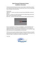
5. AlignthenotchesonthecableplugandonthebackoftheGMI10.Insertthecableintotheconnector,andturnthe
lockingringcounter-clockwiseuntilitstops.
Step 4: Connect the GMI 10 to Sensors
The GMI 10 can connect to sensors using either NMEA 2000 or NMEA 0183.
Connecting the GMI 10 through NMEA 2000
The GMI 10 is packaged with the necessary NMEA 2000 connectors and cable
to either connect the GMI 10 to your existing NMEA 2000 network, or build a
basic NMEA 2000 network. For more information on NMEA 2000, visit
www.garmin.com. Follow the directions and reference the diagrams on page 5
to either connect the GMI 10 to your existing NMEA 2000 network, or to build
a basic NMEA 2000 network.
To connect the GMI 10 to your existing NMEA 2000 network:
1. DeterminewhereyouwouldliketoconnecttheGMI10toyour
existingNMEA2000backbone.
2. DisconnectonesideofaNMEA2000T-connectorfromthebackboneatanappropriatelocation.
IfyouneedtoextendtheNMEA2000backbone,connectanappropriateNMEA2000backboneextensioncable(not
included)tothesideoftheT-connectoryoudisconnected.
3. AddtheincludedT-connectorfortheGMI10intheNMEA2000backbonebyconnectingittothesideofthe
T-connectoryoudisconnected.
4. RoutetheincludeddropcabletothebottomoftheT-connectoryoujustaddedtoyourNMEA2000network.
Iftheincludeddropcableisnotlongenough,youcanuseadropcableupto20ft.(6m)long(notincluded).
5. ConnectthedropcabletotheT-connectorandtheGMI10.
CAUTION: If you have an existing NMEA 2000 network on your boat, it should already be connected to power. Do not
connect the included NMEA 2000 power cable to an existing NMEA 2000 network, because only one power source should be
connected to a NMEA 2000 network.
To create a basic NMEA 2000 Network
1. ConnectthetwoT-connectorstogetherbytheirsides.
2. TheincludedNMEA2000powercablemustbeconnectedtoa12Vdcpowersourcethroughaswitch.Connectto
theignitionswitchoftheboatifpossible,orthroughanappropriateadditionalswitch(notincluded).
3. ConnecttheNMEA2000powercabletooneoftheT-connectors.
4. ConnecttheincludedNMEA2000dropcabletotheotherT-connectorandtotheGMI10.
5. AddadditionalT-connectorsforeachsensor(notincluded)youwanttoaddtotheNMEA2000network,andconnect
eachsensortoaT-connectorwiththeappropriatedropcable(notincluded).
6. ConnecttheappropriateterminatorstoeachendofthecombinedT-connectors.
CAUTION: You must connect the included NMEA 2000 power cable to the boat’s ignition switch, or through an external
switch. The GMI 10 will drain your battery if it is connected directly.
Power/data NMEA 2000Power/data NMEA 2000