OTC Wireless 802.11 Wireless Serial Solutions WiSER2400.IP User manual
- Category
- WLAN access points
- Type
- User manual
This manual is also suitable for

TECHNICAL MANUAL
For WiSER2400.IP
WiSER2400.Plus
802.11 Wireless Serial Solutions
http://www.otcwireless.com

WiSER 2400 Technical Manual Version 2.16 Copyright 2001-2005, OTC Wireless, Inc. All Rights Reserved Page 2 of 32
Technical Manual
For WiSER2400.IP
WiSER2400.Plus
802.11 Wireless Serial Solutions
Copyright
Information in this document is subject to change without notice. Complying
with all applicable copyright laws is the responsibility of the user. No part of
this document may be reproduced or transmitted in any form or by any means,
electronic or mechanical, for any purpose, without the express written
permission of the seller. If, however, your only means of access is electronic,
permission to print one copy is hereby granted.
The seller provides this documentation without warranty, term, or condition of
any kind. The seller may make improvements or changes in the product(s)
and/or the program(s) described in this documentation at any time.
Other product and company names herein may be trademarks of their
respective owners.
Copyright © 2001-2005, OTC Wireless, Inc. All rights reserved.
Version 2.16

WiSER 2400 Technical Manual Version 2.16 Copyright 2001-2005, OTC Wireless, Inc. All Rights Reserved Page 3 of 32
TABLE OF CONTENTS
INTRODUCTION 4
1. Installation 6
1.2 Installation of WiSER2400 Administrative Software 9
1.3 Installation of VirCOM, the virtual serial COM port redirector 9
2. WiSER Deployment Strategies 10
2.1 Using the WiSER2400 in a Point-to-point Link 10
2.2 Using the WiSER2400 in a Point-to-multiple point Link 14
3. Using the WiSER 2400 Administration Software 18
3.1 Overview 18
3.2 Password Protection 20
3.3 Link Status 21
3.4 Configuration Page 22
3.5 Encryption 27
3.6 Statistics 28
3.7 Admin 29
APPENDIX 30
Troubleshooting 30
Limited Warranty 31
Regulatory Compliance 32

WiSER 2400 Technical Manual Version 2.16 Copyright 2001-2005, OTC Wireless, Inc. All Rights Reserved Page 4 of 32
I
I
N
N
T
T
R
R
O
O
D
D
U
U
C
C
T
T
I
I
O
O
N
N
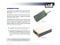
The WiSER2400.IP and the WiSER2400.Plus are IEEE 802.11b compliant
devices with built-in serial interfaces. They are designed to allow non-
wirelessly enabled serial devices to be connected and fully integrated into an
802.11 Network.
The WiSER2400 receives data from equipment with serial ports; converts the
serial data into 802.11 compliant TCP or UDP data packets and transmits
these packets wirelessly. Conversely, the WiSER can receive wireless
packets, which it unpacks and delivers byte-by-byte to the destination
equipment/device through a serial port.
The WiSER2400 requires no device driver and is operating system
independent. They can be used with almost any type of equipment that uses a
serial port, including (but not limited to) cash registers, electronic whiteboards
and navigational instruments. Administration of the WiSER2400 is done
through a Windows based administrative software program. The
administration software can be used to configure the unit’s operating
parameters, administrative and local network settings. It can also be used to
monitor the unit’s communication link conditions.
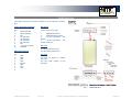
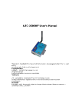
Fig. 1 WiSER2400.IP
The WiSER2400.IP comes with an RS-232 interface and a built-in
2dBi antenna. It comes supplied with a 5V DC power adapter.
The WiSER2400.Plus provides the same functionalities as the
WiSER2400.IP. It has an RS-232 DB-9 connector as well as a mini-
Phoenix connector for RS-485/422 interfaces. It accepts 5V DC to
32V DC power supply that has to be provided for separately by the
user. Input power connection is made through the mini-Phoenix
connector. It also comes with a DIN rail mounting clip and plate
assembly.
Note: Throughout this manual, the term WiSER2400 is used to
refer to both the WiSER2400.IP and the WiSER2400.Plus
Fig. 2 WiSER2400.Plus

WiSER 2400 Technical Manual Version 2.16 Copyright 2001-2005, OTC Wireless, Inc. All Rights Reserved Page 5 of 32
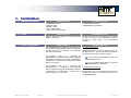
Key Features Specifications
Works with any 802.11b or 802.11g access point
Supports peer-to-peer networking with one another or any 802.11b/g
station devices
Supports TCP/IP and UDP networking over 802.11
Plug & Play operation—
o No driver on the host device is required
o Operation independent of operating system on the host
equipment or device (Windows 98/NT/2000/ME/XP, Linux, Unix,
embedded, etc.)
Supports 64-bit and 128-bit WEP encryption for secured
communication
11Mbps data rate and automatic selection of lower data rate (5.5, 2
and 1 Mbps) in degraded RF environment
Serial interface supports XON/XOFF, DTR/DSR (WiSER2400.IP and
WiSER2400.Plus) and RTS/CTS (WiSER2400.Plus) for both local
and remote hand-shake/flow control
Supports RS-232 interface (WiSER2400.IP)
Supports RS-232/485/422 interfaces, selectable by software
configuration (WiSER2400.Plus)
Compact integrated omni-directional-antenna (WiSER2400.IP)
Reverse-SMA RF connector for antenna attachment
(WiSER2400.Plus)
Microsoft-Windows-based administrative software
Protocols supported: TCP, UDP, ICMP, ARP
Comes with a virtual serial COM port redirector software, VirCOM
Model
WiSER2400.IP; WiSER2400.Plus
Standard
802.11 and 802.11b
Host Interface
RS232 (WiSER2400.IP)
RS232/485/422 (WiSER2400.Plus)
Frequency
2.4GHz – 2.497GHz
RF Channels
11 channels (US, Canada), 13 channels (Europe, Japan)
Transmission
power
16dBm at antenna input typical
RF Receiver
sensitivity
-80dBm @1e-5 BER typical
Antenna
2 dBi integrated dipole antenna (WiSER2400.IP); Reverse-
SMA RF connector (WiSER2400.Plus)
Wireless Data
Rate
11, 5.5, 2 or 1 Mbps fixed rate, or configured to automatic
rate selection
Wireless
Modulation
CCK, Direct Sequence Spread Spectrum
Wireless Link
Distance
300 ~1200 ft (WiSER2400.IP, depending on environment);
Link Distance for WiSER2400.Plus depends on antenna
used
Wireless Network
Types
Support infrastructure and ad-hoc station modes
Wireless Data
Encryption
Support the standard 64-bit and the 128-bit WEP
Network Security
MAC-address-based access control
Serial Port
Interface
Data Bit: 7/8; Parity: none/even/odd; Stop Bit: 1
Serial Data Rate
1200, 2400, 4800, 9600, 14.4K, 19.2K, 38.4K, 57.6K,
115.2K
Input Power
5VDC for WiSER2400.IP (adapter provided); 5VDC to 32
VDC for WiSER2400.Plus (to be supplied by user)
Current
consumption
<480mA (max. reached in transmit-mode)
LED Indicators
4: Power, Transmission, Receiving, Link
Operating
Temperature
-10°C – 50°C
Regulation
Compliance
FCC part 15,Class B
CE (ETSI EN 300 328-1, ETSI EN 301 489-17)
IC

WiSER 2400 Technical Manual Version 2.16 Copyright 2001-2005, OTC Wireless, Inc. All Rights Reserved Page 6 of 32
1
1
.
.
I
I
n
n
s
s
t
t
a
a
l
l
l
l
a
a
t
t
i
i
o
o
n
n
1.1.1 Standard Hardware WiSER2400.IP WiSER2400.Plus
1 WiSER2400.IP radio
1 RS232-P cable
1 RS232-C cable
1 ac-dc power adapter
1 pair of Velcro mounting pads
1 WiSER2400.PLUS radio
1 DIN Rail Mounting Assembly
1.1.2 Power WiSER2400.IP WiSER2400.Plus
Uses 5V DC for input power. An AC-to-DC power
adapter is provided.
Uses 5V DC to 32V DC for input power (to be supplied
by user). See Fig. 4 for an illustration on how to
connect the power input to the mini-Phoenix
connector.
1.1.3 Serial Connections WiSER2400.IP WiSER2400.Plus
The WiSER2400.IP has a built-in RJ-45 connector and
uses an RJ-45 to DB-9 adapter cable for connecting to
the serial port of a PC or a device. Two cables are
included in the package:
The RS-232-P cable is for connecting the
WiSER2400.IP to the RS232 port of DCE equipment
(whiteboard, instrument, etc.) during communication.
It terminates in a male DB-9 connector and is labeled
“Board” on the cable.
The RS-232-C cable is for connecting the
WiSER2400.IP to a computer or DTE equipment
during configuration using the administrative software.
It terminates in a female DB-9 connector and is
labeled “Computer” on the cable
For RS-232 Connection
WiSER2400.Plus has a built-in DB-9 connector for
RS-232 connection. User is to provide the proper RS-
232 cable for connection to a PC or a device.
Use a null-modem serial cable to connect the
WiSER2400.Plus to a PC.
Use a straight-thru serial cable to connect the
WiSER2400.Plus to a DCE device
For RS-485/422 Connection
Please refer to Fig. 4 for connecting the RS-485 and
RS-422 data lines to the mini-Phoenix connector on
the WiSER2400.Plus.

WiSER 2400 Technical Manual Version 2.16 Copyright 2001-2005, OTC Wireless, Inc. All Rights Reserved Page 7 of 32
1.1.4 Selecting the Serial Mode for WiSER2400.Plus
WiSER2400.IP
The WiSER2400.Plus has a 4-position dipswitch next to the mini Phoenix
connector for selecting the serial operating mode:
RS-232
RS-485
(select RS-485 and half-duplex)
RS-422
(select RS-485 and full-duplex)
The factory default has the dipswitch set in the RS-232 mode. Please refer to
Fig. 4 for details in setting the dipswitch for different operating modes.
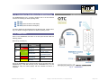
1.1.5 Status LEDs
Power on the WiSER2400, the LEDs on the front panel should exhibit the
following patterns:
(Refer to Fig. 3 and Fig. 4)
LED Color Light Blinking
Pattern
Indication
ON RED
Steady on
Proper power is
supplied
Steady on
Unit is linked to a
wireless system
RX GREEN
Steady blink
Unit is not linked to
any wireless system
TX RED
On when
transmitting
Unit is transmitting
RF signal
LINK
YELLOW
Blinking
Serial Mode
Secure the WiSER2400 at the desired location with the provided Velcro (for
WiSER2400.IP) or DIN Rail mounting kit (for WiSER2400.Plus) once the
hardware is setup and works properly with the intended host device or
equipment.
Fig. 3 WiSER2400.IP

WiSER 2400 Technical Manual Version 2.16 Copyright 2001-2005, OTC Wireless, Inc. All Rights Reserved Page 8 of 32
WiSER2400.Plus
This section describes the signals expected on the mini-Phoenix connector
pins.
10-pin mini-Phoenix terminal
:
Pin:
1. DATA+(RS-485)
2. DATA- (RS-485)
3. N/C
4. TX+ (RS-422)
5. TX- (RS-422)
6. RX+ (RS-422)
7. RX- (RS-422)
8. N/C
9. V+ (Up to +32 VDC)
10. GROUND
DB 9 male connector
:
Pin:
1. DCD
2. RXD
3. TXD
4. DTR
5. Ground
6. DSR
7. RTS
8. CTS
9. -
Dip Switch
:
Location (from left to right)
1. #RS232/485 selector
2. #Full/Half duplex selector
3. 120 ohm termination -- 422
RX pair
4. 120 ohm termination -- 422
TX pair or 485 pair.
For 1 & 2
:
The level up position is high.
The level down position is low.
For 3 & 4
:
The level up position is without
terminator.
The level down position is with
terminator.
Fig. 4 WiSER2400.Plus

WiSER 2400 Technical Manual Version 2.16 Copyright 2001-2005, OTC Wireless, Inc. All Rights Reserved Page 9 of 32
1.2 Installation of WiSER2400
Administrative Software
1.3 Installation of VirCOM, the virtual
serial COM port redirector
1.2.1 System Requirements 1.3.1 System Requirements
To support the WiSER2400 administrative software, the computer must meet
the following minimum requirements:
Windows®98 (SE)/ NT/ ME/ 2000/ XP
One COM port (with a DB-9 male connector or an appropriate
adapter to connect to a DB-9 female connector)
(Optional) A TCP/IP wireless network that connects the PC running
the administrative program and the WiSER2400 unit.
To support the WiSER2400 administrative software, the computer
must meet the following minimum requirements:
Windows®98 (SE)/ NT/ ME/ 2000/ XP
Active TCP/IP services
VirCOM files are under the VirCOM folder on the distribution CD-ROM.
1.2.2 Installation
1.3.2 Installation
To install the administrative program, simply insert the distribution CD-ROM
into the CD-ROM drive. Copy the “wauti_nnnn.exe” file to the desired hard-
drive location on the PC (where ‘nnnn’ is a number).
Click on the setup.exe to install VirCOM.
See the VirCOM Technical Manual for the detail information on using VirCOM.

WiSER 2400 Technical Manual Version 2.16 Copyright 2001-2005, OTC Wireless, Inc. All Rights Reserved Page 10 of 32
2
2
.
.
W
W
i
i
S
S
E
E
R
R
D
D
e
e
p
p
l
l
o
o
y
y
m
m
e
e
n
n
t
t
S
S
t
t
r
r
a
a
t
t
e
e
g
g
i
i
e
e
s
s
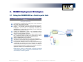
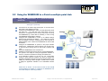
2.1 Using the WiSER2400 in a Point-to-point Link
2.1.1 Using the WiSER2400 in a point-to-point link
Scheme 1
See Figure 5 (overleaf)
Connect the PC to an 802.11b/g access point, or use a PC with a
built-in 802.11b/g wireless LAN card.
Configure the WiSER2400 to match its serial parameters (baud rate,
parity bit, … etc.) with that of the serial device it is to be attached to.
Configuration can be done by temporarily connecting the
WiSER2400, by a serial cable or wirelessly, to a PC running the
WiSER2400 administration software.
Configure the WiSER2400 to match up its TCP/UDP/IP settings
(listening port, destination IP address, … etc.) with that on the PC
side for a TCP/IP or UDP/IP connection.
Configure the WiSER2400 to operate in the proper wireless network
type: Infrastructure mode for linking to an access point, or Ad-hoc
mode for linking with a PC with a built-in wireless LAN card.
Attach the WiSER2400 to the serial device.
Establish the wireless link between the PC and the WiSER2400.
The system is now ready for running the application software on the
PC to control the serial device through the wireless link.
If the application software on the PC can only communicate through
a serial COM port interface and does not support the standard
TCP/UDP/IP protocols through the network interface, the COM port
re-directing software program, VirCOM, will be needed to bridge the
application software to the TCP/UDP/IP network port.
Please refer to Section 3 of this manual as well as the VirCOM
Technical Manual for details on configuring the WiSER2400 and the
Virtual COM port re-directing software.

WiSER 2400 Technical Manual Version 2.16 Copyright 2001-2005, OTC Wireless, Inc. All Rights Reserved Page 11 of 32
Fig. 5

WiSER 2400 Technical Manual Version 2.16 Copyright 2001-2005, OTC Wireless, Inc. All Rights Reserved Page 12 of 32
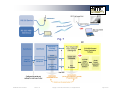
2.1.2 Using the WiSER2400 in a point-to-point link
Scheme 2
See Figure 6 (overleaf)
Configure the WiSER2400 on the device side to match its serial
parameters (baud rate, parity bit, … etc.) with that of the serial
device it is to be attached to. Configuration can be done by
temporarily connecting the WiSER2400, by a serial cable or
wirelessly, to a PC running the WiSER2400 administration software.
Similarly, configure the serial parameters of the WiSER2400 on the
PC side so that it can communicate with the PC.
Configure the WiSER2400s on either side of the link to match up
their TCP/UDP/IP settings (listening port, destination IP address, …
etc.) for a TCP/IP or UDP/IP connection.
Configure the WiSER2400s on both sides to operate in the Ad-hoc
mode.
Attach the WiSER2400s to the serial device and the PC.
Establish the wireless link between the PC and the WiSER2400.
The system is now ready for running the application software on the
PC to control the serial device through the wireless link.
Please refer to Section 3 of this manual for details on configuring the
WiSER2400.

WiSER 2400 Technical Manual Version 2.16 Copyright 2001-2005, OTC Wireless, Inc. All Rights Reserved Page 13 of 32
Fig. 6

WiSER 2400 Technical Manual Version 2.16 Copyright 2001-2005, OTC Wireless, Inc. All Rights Reserved Page 14 of 32
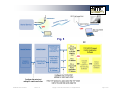
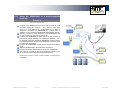
2.2 Using the WiSER2400 in a Point-to-multiple point Link
2.2.1 Using the WiSER2400 in a point-to-multiple
point link
Scheme 3
See Figure 7 (overleaf)
Connect the PC to an 802.11b/g access point, or use a PC with a
built-in 802.11b/g wireless LAN card.
Configure each WiSER2400 to match its serial parameters (baud
rate, parity bit, … etc.) with that of the serial device it is to be
attached to. Configuration can be done by temporarily connecting
the WiSER2400, by a serial cable or wirelessly, to a PC running
the WiSER2400 administration software.
Configure each WiSER2400 to match up its UDP/IP settings
(listening port, destination IP address, … etc.) with that on the PC
side for a UDP/IP connection. Configure the PC side to operate in
UDP broadcast mode. Enable each WiSER2400 to receive UDP
broadcasts.
Configure the WiSER2400s to operate in the proper wireless
network type: Infrastructure mode for linking to an access point,
or Ad-hoc mode for linking with a PC with a built-in wireless LAN
card.
Attach the WiSER2400s to the serial devices.
Establish the wireless link between the PC and the WiSER2400s.
The system is now ready for running the application software on
the PC to control the serial devices through the wireless link.
If the application software on the PC can only communicate
through a serial COM port interface and does not support the
standard TCP/UDP/IP protocols through the network interface, the
COM port re-directing software program, VirCOM, will be needed
to bridge the application software to the TCP/UDP/IP network
port.
Please refer to Section 3 of this manual as well as the VirCOM
Technical Manual for details on configuring the WiSER2400 and
the Virtual COM port re-directing software.

WiSER 2400 Technical Manual Version 2.16 Copyright 2001-2005, OTC Wireless, Inc. All Rights Reserved Page 15 of 32
Fig. 7

WiSER 2400 Technical Manual Version 2.16 Copyright 2001-2005, OTC Wireless, Inc. All Rights Reserved Page 16 of 32
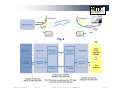
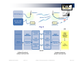
2.2.2 Using the WiSER2400 in a point-to-multiple
point link
Scheme 4
See Figure 8 (overleaf)
Configure each WiSER2400 on the device side to match its serial
parameters (baud rate, parity bit, … etc.) with that of the serial
device it is to be attached to. Configuration can be done by
temporarily connecting the WiSER2400, by a serial cable or
wirelessly, to a PC running the WiSER2400 administration software.
Similarly, configure the serial parameters of the WiSER2400 on the
PC side so that it can communicate with the PC.
Configure the WiSER2400s on either side of the link to match up
their UDP/IP settings (listening port, destination IP address, … etc.)
for a UDP/IP connection. Enable the WiSER2400 on the PC side to
send UDP broadcasts. Enable each WiSER2400 on the device side
to receive UDP broadcasts.
Configure the WiSER2400s on both sides to operate in the Ad-hoc
mode.
Attach the WiSER2400s to the serial device and the PC.
Establish the wireless link between the PC and the WiSER2400.
The system is now ready for running the application software on the
PC to control the serial devices through the wireless link.
Please refer to Section 3 of this manual for details on configuring the
WiSER2400.

WiSER 2400 Technical Manual Version 2.16 Copyright 2001-2005, OTC Wireless, Inc. All Rights Reserved Page 17 of 32
Fig. 8

WiSER 2400 Technical Manual Version 2.16 Copyright 2001-2005, OTC Wireless, Inc. All Rights Reserved Page 18 of 32
3
3
.
.
U
U
s
s
i
i
n
n
g
g
t
t
h
h
e
e
W
W
i
i
S
S
E
E
R
R
2
2
4
4
0
0
0
0
A
A
d
d
m
m
i
i
n
n
i
i
s
s
t
t
r
r
a
a
t
t
i
i
o
o
n
n
S
S
o
o
f
f
t
t
w
w
a
a
r
r
e
e
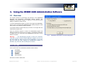
3.1 Overview
This chapter describes the functionality and operations of the WiSER2400
Diagnostic and Configuration administrative software program. The
WiSER2400 administrative program is supported on Microsoft Windows®
98(SE), NT, Millennium, 2000, and XP.
To use the administrative program to monitor and configure the WiSER2400,
the PC can be connected to the WiSER2400 either directly through the serial
port by cable or via a wireless network connection.
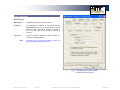
A connection selection window will pop up as shown on the right when the
administrative program starts.
Once the connection selection is chosen, the administrative program will
display an interface as shown in Fig. 10 and Fig. 11 respectively, depending
on whether the PC is connected to the WiSER2400 by serial port, or by a
wireless connection.
Warning: The administrative program in serial port connection
mode will not work if another RS232 application program is set to use
the same COM port. Make sure that no other application is connected
with the COM port when starting the administrative program. In
Windows, any connection with a COM port is exclusive.
3.1.1 The Tabs
There are five Tabs in the administrative software interface window:
Link Status
Configuration
Encryption
Statistics
Administration
Each will be covered in detail below.
Fig. 9 WiSER2400 administration connection dialog panel

WiSER 2400 Technical Manual Version 2.16 Copyright 2001-2005, OTC Wireless, Inc. All Rights Reserved Page 19 of 32
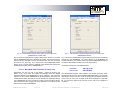
Fig. 10 Administrative software dialog with a PC connected to the
WiSER2400 via a serial cable
Fig. 11 Administrative software dialog with a PC connected to the
WiSER2400 wirelessly.
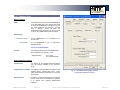
Fig. 10 shows the administrative program interface when the PC is connected
with the WiSER2400 through the serial port by a cable. The user first needs to
select the proper COM port on the PC and its baud rate, byte size, and parity
(as shown in the top of Fig. 10) to match those of the WiSER2400 before
clicking on the “Connect” button to establish communication link between the
administrative program and the WiSER2400 unit.
Defaults: Baud Rate: 9600 / Data bits: 8 / Parity: none
Alternatively, the user can click on the “Detect…” button (as shown in the
bottom of Fig. 10) to have the software automatically detect the RS232
parameter settings of the WiSER2400 at a given COM port. The connection
between the PC and the WiSER2400 will be automatically made when the
administrative software succeeds in correctly detecting the parameter settings
of the WiSER2400. Once the connection is made, the Connect button will turn
into a Disconnect button. Simply click on the “Disconnect” to terminate the link
between the PC and the WiSER2400.
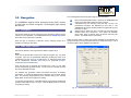
Fig. 11 shows the administrative program interface when the PC is wirelessly
connected to the WiSER2400. To connect the PC to the WiSER2400 via
wireless networking, one needs to make sure that the WiSER2400 and the PC
running the administrative software are on the same subnet.
The default IP settings for the WiSER2400 are:
IP address: 192.168.11.191
Subnet mask: 255.255.255.0
The administrative program, when started in the wireless connection mode,
will automatically scan for all the available WiSER2400 units on the network.
Alternatively, the user can force a scan by clicking the “Get MAC/IP” button as
shown in the top of Fig. 4b. The scan results will be displayed in a pull-down
list. The user then selects from the menu for the unit to be configured or
monitored.

WiSER 2400 Technical Manual Version 2.16 Copyright 2001-2005, OTC Wireless, Inc. All Rights Reserved Page 20 of 32
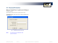
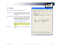
3.2 Password Protection
Before any change/modification can be made to the configuration of a
WiSER2400, a password must be submitted before the configuration
command is executed.
After entering the password, click “OK” to proceed “Cancel” to stop.
The Password Utility is also used to add or change a password for a
WiSER2400 unit.
Fig. 12 WiSER2400 Password Utility panel
NOTE: The default password of WiSER2400 is none.
(Leave the field blank).
Page is loading ...
Page is loading ...
Page is loading ...
Page is loading ...
Page is loading ...
Page is loading ...
Page is loading ...
Page is loading ...
Page is loading ...
Page is loading ...
Page is loading ...
Page is loading ...
-
 1
1
-
 2
2
-
 3
3
-
 4
4
-
 5
5
-
 6
6
-
 7
7
-
 8
8
-
 9
9
-
 10
10
-
 11
11
-
 12
12
-
 13
13
-
 14
14
-
 15
15
-
 16
16
-
 17
17
-
 18
18
-
 19
19
-
 20
20
-
 21
21
-
 22
22
-
 23
23
-
 24
24
-
 25
25
-
 26
26
-
 27
27
-
 28
28
-
 29
29
-
 30
30
-
 31
31
-
 32
32


OTC Wireless 802.11 Wireless Serial Solutions WiSER2400.IP User manual
- Category
- WLAN access points
- Type
- User manual
- This manual is also suitable for
Ask a question and I''ll find the answer in the document
Finding information in a document is now easier with AI
Related papers


Other documents
-
Quatech SS-BLT-300 User manual
-
Quatech SS-BLT-400 User manual
-
Square D WISEREMCTEXT25 User manual
-
 ATC Technology ATC-2000WF User manual
-
 StarTech.com ATC-2000WF User manual
-
Schneider Electric Wiser Window and Door Sensor (PDL) - Device User guide
-
-
-
-

