Page is loading ...

Installation Guide
Wiser Air
™
Thermostat
Guide for Residential Users

Wiser Air Installation Guide V13
www.wiserhome.com
3
English
Safety Information
Read these instructions carefully and look at the equipment to become familiar
with the device before trying to install, operate, service or maintain it. The
following special messages may appear throughout this installation guide or
on the equipment to warn of potential hazards or to call attention to information
that claries or simplies a procedure.
The addition of either symbol to a “Danger” or “Warning” safety label
indicates that an electrical hazard exists which will result in personal
injury if the instructions are not followed.
This is the safety alert symbol. It is used to alert you to potential personal
injury hazards. Obey all safety messages that follow this symbol to avoid
possible injury or death.
DANGER indicates a hazardous situation which, if not avoided, will result in death
or serious injury.
WARNING indicates a hazardous situation which, if not avoided, could result in
death or serious injury.
NOTICE is used to address practices not related to physical injury.
Please Note
Electrical equipment should be installed, operated, serviced, and maintained only by
qualied personnel. No responsibility is assumed by Schneider Electric for any conse-
quences arising out of the use of this material.
A qualied person is one who has skills and knowledge related to the construction,
installation, and operation of electrical equipment and has received safety training to
recognize and avoid the hazards involved.
WARNING
DANGER
NOTIC
E

4
English
© 2015 Schneider Electric. All rights reserved.
Wiser Air Installation Guide V13
www.wiserhome.com
Wiser Air Installation Guide V13
www.wiserhome.com
5
English
Before You Start
Read the information in this section in its entirety before you begin the installation of
Wiser Air.
REQUIRED TOOLS PROVIDED MATERIALS
• Wire stripper
• Drill
• Screwdriver
• Level
• Wiser Air front
• Wiser Air back plate
• Wiser Air trim plate
• Screws (x2) and anchors (x2)
• Wire extender
• Installation guide
Preparation
1. Ensure Wiser Air is suitable for the environment. Check the voltage
compatibility. A thick wire (110V or 220V) is not compatible with Wiser Air, two thin
wires (24V) are needed. Acceptable wire gauge for use with Wiser Air is solid 16 to
24 AWG (1.31 to 0.205mm²).
2. Disconnect power to the air conditioning and/or heating system.
3. Use a properly isolated voltage sensing device to conrm power is off.
4. Wiring must conform to all building codes, regulations, and ordinances as required
by local and national code and regulation authorities.
5. Ensure all electrical loads (air conditioners, heating elements, etc.) that will be
controlled by Wiser Air are connected to appropriate fuses to prevent overload.
Location
• If this is a new installation, install Wiser Air ve feet above the oor surface in
accordance with applicable building codes.
• Install Wiser Air in areas with frequent occupancy and airow.
• Avoid installing Wiser Air in locations near heating/cooling devices.
• Avoid installing Wiser Air in areas with direct sunlight. The screen may become
unreadable due to direct sunlight or reection from windows, and temperature
regulation may be affected.
• Never install Wiser Air behind doors, near corners, near air vents, or in areas with
high dust concentration.
Mounting
1. Keep the front of Wiser Air separate from the back plate before mounting.
2. Align the Wiser Air back plate against a wall using a level and mark the placement
of the mounting holes.
3. Drill holes and install wall anchors at the marked locations. If a stud is present no
anchors are necessary. Always check for wires and pipes before drilling.
Cleaning and care
1. Use a soft, lint-free dry cloth for cleaning.
2. Avoid getting moisture in openings.
3. Do not use cleaning products or compressed air.
4. Never use tools directly on the touchscreen.
5. Never use paint on Wiser Air.
6. Do not drop or crush Wiser Air, or allow Wiser Air to come into contact with liquids.
7. Do not use a damaged device (such as one with a cracked screen) as it may
cause injury.
8. Functionality guarantees are no longer valid if the glass on the screen is broken.
Wiser Air product support
The Customer Care Center (CCC) is your single point of contact for
information about your Wiser Air. Qualied personnel are available to answer your
customer service and technical support questions.
PHONE: 1-855-55WISER (1-855-559-4737)
E-Mail: [email protected]
Web: www.wiserhome.com/support
Installation Procedure
WARNING MERCURY HAZARD
If replacing an existing thermostat that uses a sealed tube of mercury, do not
dispose of the tube in the trash. Contact local waste management authorities for
infomation on the safe disposal or recycling of the mercury.
Failure to safely dispose of the mercury can result in exposure
leading to serious health damage.
Optional trim plate mounting
If you are replacing an existing thermostat you have the option of using the provided
Wiser Air trim plate. If the hole left by the removal of the existing unit is larger than the
back plate of the Wiser Air thermostat, use the optional trim plate. Run the wires and
anchor the mounting screws through it while attaching the back plate to the wall
(Fig. 2). Make sure to attach the trim plate with the central hole oriented upwards.
WARNING

6
English
© 2015 Schneider Electric. All rights reserved.
Wiser Air Installation Guide V13
www.wiserhome.com
Wiser Air Installation Guide V13
www.wiserhome.com
7
English
Installing Wiser Air
1. Disconnect power to the HVAC system by turning off the breaker.
2. Remove the existing thermostat’s panel from the wall without disconnecting the
wiring.
3. Take a picture of the wiring of the terminal connections. If necessary label the
wires to prevent confusion (Fig. 1).
Figure 1. Removal of
existing thermostat and
photograph of wiring.
TIP: Before proceeding further determine if you require the optional trim plate.
TIP: Before proceeding further check if you require a wire extender
(see Appendix).
4. Disconnect the wiring of the existing thermostat and remove the back plate.
5. Pull the wires 6in (15cm) out of the wall if they are not already pulled out.
6. Insert the wires through the central hole in Wiser Air back plate.
7. If required, strip each wire 0.25in (0.6cm) from the end (does not apply to
replacing pre-existing units).
8. Connect the wiring to the Wiser Air back plate, matching the terminal connections
to those in the photograph of the existing thermostat’s wiring or according to the
wiring requirements of your HVAC system.
TIP: See the Wiring terminals section (p.9) in this guide before going further,
or contact Wiser Product Support for assistance if necessary.
Figure 2. Wiring connection and back plate attachment (optional trim plate shown).
TIP: To verify the compatibility of your unit – please visit
www.wiserhome.com/compatibility

8
English
© 2015 Schneider Electric. All rights reserved.
Wiser Air Installation Guide V13
www.wiserhome.com
Wiser Air Installation Guide V13
www.wiserhome.com
9
English
Figure 3. Front to back plate mounting.
9. Gently push the wiring back into the hole.
10. Attach the Wiser Air back plate to the wall using the provided screws in the
mounting holes in the top and bottom (Fig. 2).
11. Attach the front of Wiser Air to the back plate, making sure that the front is oriented
correctly so that the terminal pins on the front panel match the pins on the back
plate. Do not use excessive force on the Wiser Air as this can damage the terminal
pins (Fig. 3).
12. Remove the protective plastic cover from the LCD touchscreen.
13. Reconnect power to the HVAC system.
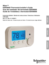
Wiring terminals
This section describes the procedure for connecting the wiring to the back plate.
Figure 4 shows the Wiser Air backplate conguration.
When replacing an older thermostat, refer to the photograph of the original wiring
taken in Step 3 of the installation procedure to connect the wiring to the correct
terminals. See the caution below.
For a new installation, consult the documentation for your HVAC system to determine
the correct wiring terminal connections. Match the wiring labels to the terminal labels.
For more information or assistance in determining the correct wiring for your HVAC
system, see the HVAC wiring help sections on the Wiser Air website
(www.wiserhome.com/support) or contact Wiser Air Product Support.
RC
G
W2
Y2
O/B
S1
C
RH
W
Y
U
S2
Figure 4. Wiring terminals and jumper.
Failure to remove
this jumper can
cause damage to
your Wiser Air.
EQUIPMENT
OPERATION HAZARD
• If a wire is connected
to the RH terminal
you must remove the
backplate jumper.
• Never use any tools
on screwless termi-
nals of Wiser Air.
Save the jumper for
future use.
NOTIC
E

10
English
© 2015 Schneider Electric. All rights reserved.
Wiser Air Installation Guide V13
www.wiserhome.com
Wiser Air Installation Guide V13
www.wiserhome.com
11
English
Troubleshooting
If you experience difculties with your Wiser Air thermostat setup, proceed as follows:
• Disconnect power.
• Check that the front plate of Wiser Air is properly connected to the back plate.
• Check that the wires connected to the terminals on the back plate are properly
attached.
TIP: If you are unsure whether your wiring requires the use of the Wiser Air
jumper, remove the jumper and test the system to see if the heating
comes on. If it does, your installation is complete. If it does not, contact
Wiser Air customer support.
Terminal Descriptions
RC Cool 24V power supply Required
G Fan relay
W2 Heating relay (Stage 2)
Y2 Compressor relay (Stage 2)
O/B Cool / Heat active reversing valve
S1 Outside air sensor
C Common Required
RH Heat 24V power supply Only if RC is connected
W Heating relay
Y Compressor relay
U Universal (W3)
S2 Outside air sensor
Connection Specication Notes
Touchscreen Display
Installation wizard
When installing a new Wiser Air for the rst time, an installation wizard will launch
to guide you through the initial conguration and registration of the device as soon
as the device is connected. Follow the instructions shown. For more information,
go to: www.wiserhome.com/support.
TIP: For on-the-go control of your Wiser Air thermostat, download the app from
the App Store or Google Play.
Welcome to
WiserAir
Begin
Smart Sense Display
Wiser Air has a built-in advanced motion sensor. When it detects a person in proximity, it
will show a limited display.
In order to conserve energy, the display is inactive when no presence is detected by the
sensor.
Figure 5. Wiser Air welcome screen.

12
English
© 2015 Schneider Electric. All rights reserved.
Wiser Air Installation Guide V13
www.wiserhome.com
Wiser Air Installation Guide V13
www.wiserhome.com
13
English
Interactive display
When a user interacts with Wiser Air’s touchscreen, the display will change to show
the following information.
For more information on Wiser Air’s functionality, please consult the online user guide
at: https://www.wiserhome.com/support
Figure 6. Interactive display.
Brings up the display of the
Home, Sleep and Away
Ready Modes
Brings up the Override
Schedule, which lists the
timing of Ready Mode
changes performed by
Wiser Air
Displays the menu
options available
Inside
temperature
controls
Current weather
and outside
temperature
Appendix
Wiser Wire Extender Kit
Introduction
The Wiser Wire Extender Kit is intended for use when a common wire (C) from the
HVAC control board is not available. If you are unsure whether you have the HVAC
wire present, refer to the picture taken in Step 3 of the Installation procedure for Wiser
Air. The picture can also help you determine whether you have a 4 or 5-wire system
in place.
The wire extender kit contains a diode pair and a Printed Control Board (PCB)
assembly. To open the board pinch and pull (Fig. 7).
Figure 7. Wire Extender Kit.
W
Y
HAZARD OF ELECTRICAL SHOCK
The following installation procedure should be performed by qualied personnel:
• Knowledgeable about and licensed in accordance with local electrical
installation code requirements.
• Able to read, interpret, and follow the instructions and precautions provided.
• Trained on the operation and fundamentals of residential HVAC apparatus, and
familiar with the associated hazards.
Failure to follow these instructions can result in personal injury and/or
damage to Wiser Air.
WARNING

14
English
© 2015 Schneider Electric. All rights reserved.
Wiser Air Installation Guide V13
www.wiserhome.com
Wiser Air Installation Guide V13
www.wiserhome.com
15
English
Installation
HAZARD OF ELECTRIC SHOCK, EXPLOSION OR ARC FLASH
Disconnect all power before working on equipment.
Failure to follow these instructions will result in death or
serious injury.
TIP: Take a photograph of the initial wiring of the HVAC system to use as
a reference and to help prevent wiring mishaps during the installation
process.
1. Disconnect the wires from the Y and W terminals on the thermostat.
2. Connect the diode pair to the Y and W terminals (Fig. 8). Ensure that the diode
pair’s Y terminal is connected to the thermostat’s Y terminal and the diode pair’s
W terminal is connected to the thermostat’s W terminal.
3. Connect both wires that were disconnected from the thermostat base in Step 1
to their corresponding points on the diode pair.
4. Connect the other wire that was disconnected from the thermostat base to the C
terminal on the thermostat.
RC
G
W2
Y2
O/B
S1
C
RH
U
S2
W
Y
Figure 8. Diode pair
connection.
This wire con-
nects to the W
on the Wire
Extender
terminal.
DANGER
1. Isolate power from the HVAC
system.
2. Familiarize yourself with the HVAC
control board located inside the air
handler system.
3. Relocate the wire from the R
terminal on the HVAC control board
to the RC or RH terminal on the
STAT side of the PCB assembly.
Ensure that the jumper between the
RC and RH terminals is installed.
4. Relocate the wire from the G
terminal on the HVAC control board
to the G terminal on the STAT side
of the PCB assembly.
5. Connect the wire at the C terminal
of the thermostat to the C terminal
on the STAT side of the PCB as-
sembly.
6. Connect the wire from the common
point of the diode pair to either the
W or Y terminal on the STAT side
of the PCB assembly. Ensure that
the jumper between the W and Y
terminals is installed.
7. Connect the wires between ter-
minals RC, Y, W, C, and G on the
HVAC control board and the EQUIP
side of the PCB assembly.
8. Connect RC, Y, W, C, and G on the
HVAC control board to RC, Y, W,
C, and G on the EQUIP side of the
wire extender respectively.
9. Mount the PCB assembly near the
HVAC control board.
RC
RC R Y W C G
STAT EQUIP
C RCY
RH Y W C G
HVAC EQUIPMENT
RC
G
W2
Y2
O/B
S1
C
RH
W
Y
U
S2
WISER AIR BACK PLATE
WIRE TO HVAC SIDE
WIRE TO WISER AIR SIDE
RH W C G
W
Y
Installing the wire extender kit in a 4-wire system
Figure 9. PCB Installation
in a 4-wire system.

16
English
© 2015 Schneider Electric. All rights reserved.
Wiser Air Installation Guide V13
www.wiserhome.com
Wiser Air Installation Guide V13
www.wiserhome.com
17
English
Installing the wire extender kit in a 5-wire system
In order to complete this procedure, ensure that the RC/RH jumper on the STAT side
of the PCB is unscrewed and removed.
Figure 10. Wire extender jumper removal.
STAT EQUIP
G C Y
RH Y W C G
RC R Y W C G
RH Y W C G
HVAC EQUIPMENT
RC
WIRE TO HVAC SIDE
RC
G
W2
Y2
O/B
S1
C
RH
W
Y
U
S2
WISER AIR BACK PLATE
WIRE TO WISER AIR SIDE
W
Y
RH
W
C G
RC
Figure 11. PCB Installation in a 5-wire system.
Installing the wire extender kit in a 5-wire system
1. Isolate power from the HVAC
system.
2. Familiarize yourself with the HVAC
control board located inside the air
handler system.
3. Relocate the wire from the RC
terminal on the HVAC control
board to the RC terminal on the
STAT side of the PCB assembly.
4. Connect the wire relocated from
terminal RH on the HVAC control
board to terminal RH on the STAT
side of the PCB assembly.
5. Relocate the wire from the G ter-
minal on the HVAC control board
to the G terminal on the STAT side
of the PCB assembly.
6. Connect the wire at the C terminal
of the thermostat to the C terminal
on the STAT side of the PCB
assembly.
7. Mount the PCB assembly near the
HVAC control board.
8. Connect the wire from the common
point of the diode pair to either the
W or Y terminal on the STAT side
of the PCB assembly. Ensure that
the jumper between the W and Y
terminals is installed.
9. Connect the wires between the
RC, RH, Y, W, C, and G terminals
on the HVAC control board to RC,
RH, Y, W,C and G on the EQUIP
side of the wire extender respec-
tively.

18
English
© 2015 Schneider Electric. All rights reserved.
Wiser Air Installation Guide V13
www.wiserhome.com
Electrical equipment should be installed, operated, serviced, and maintained only by qualied personnel. No
responsibility is assumed by Schneider Electric for any consequences arising out of the use of this material.
© 2015 Schneider Electric. All rights reserved.
Schneider Electric and Wiser are trademarks owned by Schneider Electric Industries SAS or its afliated
companies. All other trademarks are the property of their respective owners.
/