
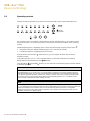
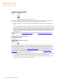
ABB i-bus
®
KNX
DALI Light Controller DLR/S 8.16.1M
Product Manual


ABB i-bus
KNX
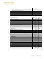
Contents
DLR/S 8.16.1M | 2CDC 507 100 D0202 i
Contents
Page
1 General ................................................................................................. 3
1.1 Using the product manual .............................................................................................................4
1.1.1 Structure of the product manual ...................................................................................................4
1.1.1.1 Software Tool ...............................................................................................................................4
1.1.2 Notes ............................................................................................................................................5
1.2 Product and functional overview ...................................................................................................6
1.3 DALI principles for the DLR/S .......................................................................................................8
1.3.1 DALI group control ........................................................................................................................9
2 Device technology ............................................................................. 11
2.1 DLR/S 8.16.1M ........................................................................................................................... 12
2.1.1 Technical data DLR/S 8.16.1M ................................................................................................... 12
2.1.2 Connection diagram DLR/S 8.16.1M .......................................................................................... 15
2.1.3 Dimensional drawing DLR/S 8.16.1M ......................................................................................... 17
2.2 Light Sensor LF/U 2.1 ................................................................................................................. 18
2.2.1 Technical data LF/U 2.1.............................................................................................................. 18
2.2.2 Connection diagram LF/U 2.1 ..................................................................................................... 20
2.2.3 Dimensional drawing LF/U 2.1 .................................................................................................... 21
2.2.4 Polar diagram LF/U 2.1............................................................................................................... 22
2.2.5 Checking the LF/U 2.1 ................................................................................................................ 22
2.3 Mounting and installation ............................................................................................................ 23
2.4 Description of the DALI output .................................................................................................... 25
2.5 Display elements ........................................................................................................................ 26
2.6 Operating controls ...................................................................................................................... 28
3 Commissioning .................................................................................. 31
3.1 Overview..................................................................................................................................... 32
3.1.1 Conversion ................................................................................................................................. 35
3.1.1.1 Conversion procedure ................................................................................................................ 36
3.1.2 Copying and exchanging parameter settings.............................................................................. 37
3.1.2.1 Procedure for copy and exchange .............................................................................................. 38
3.1.2.2 Functional overview .................................................................................................................... 39
3.1.3 Overlapping lighting groups ........................................................................................................ 41
3.2 Parameter ................................................................................................................................... 42
3.2.1 Parameter window General ........................................................................................................ 43
3.2.2 Light sensor parameter window .................................................................................................. 51
3.2.3 Parameter window Central ......................................................................................................... 53
3.2.3.1 Parameter window Status - Central ............................................................................................ 61
3.2.3.2 Parameter window Gx Group ..................................................................................................... 67
3.2.3.2.1 Parameter window - Gx Status ................................................................................................... 77
3.2.3.2.2 Parameter window - Gx Fault ..................................................................................................... 81
3.2.3.2.3 Parameter window - Gx Functions .............................................................................................. 86
3.2.3.2.4 Parameter window - Gx Staircase lighting .................................................................................. 94
3.2.3.2.5 Parameter window - Gx Light controller ...................................................................................... 99
3.2.3.2.6 Parameter window - Gx Control Operating ............................................................................... 107
3.2.3.2.7 Parameter window - Gx Slave .................................................................................................. 112
3.2.4 Parameter window Scenes ....................................................................................................... 117
3.2.4.1 Parameter window Scene x ...................................................................................................... 118
3.3 Communication objects ............................................................................................................ 121
3.3.1 Summary of communication objects ......................................................................................... 122
3.3.2 Communication objects General ............................................................................................... 124
3.3.3 Communication objects DALI output ........................................................................................ 132
3.3.4 Communication objects Group x ............................................................................................... 144
3.3.5 Communication objects Scene x/y ............................................................................................ 150
3.3.6 Communications object Light control ........................................................................................ 152
3.3.7 Communication objects Slave function ..................................................................................... 155
3.3.8 Communication objects Staircase lighting function ................................................................... 157

ABB i-bus
KNX
Contents
ii 2CDC 507 100 D0202 | DLR/S 8.16.1M
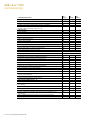
4 Planning and application ................................................................. 159
4.1 Automatic DALI addressing ..................................................................................................... 159
4.2 Function diagram ..................................................................................................................... 160
4.3 Monitoring of lamps and ballasts ............................................................................................. 162
4.4 Exchange of DALI devices ....................................................................................................... 163
4.5 Effect of ageing on lighting equipment ..................................................................................... 164
4.6 Burning-in of lighting equipment .............................................................................................. 165
4.7 Control telegram and status with a communication object ....................................................... 166
4.8 Staircase lighting ..................................................................................................................... 167
4.8.1 Staircase lighting with Light control function ............................................................................ 170
4.9 Constant light control ............................................................................................................... 171
4.9.1 Changing the setpoint .............................................................................................................. 175
4.9.2 Deactivation of constant light control ....................................................................................... 176
4.9.3 Activating constant lighting control ........................................................................................... 176
4.9.4 Follow-up time of the inactive light control ............................................................................... 177
4.9.5 Commissioning/calibration of the constant lighting control ....................................................... 177
4.9.6 Brightness detection function ................................................................................................... 183
4.9.7 Function of the constant lighting control................................................................................... 183
4.10 Scene....................................................................................................................................... 187
4.11 Slave ........................................................................................................................................ 190
4.11.1 Slave with offset function ......................................................................................................... 193
4.12 DALI dimming curve................................................................................................................. 195
4.12.1 Characteristic adjustment of the linear lighting curve ............................................................... 197
4.12.2 Characteristic adjustment of phys-min dimming value ............................................................. 198
A Appendix ........................................................................................... 199
A.1 Code table Diagnostics Low byte (no. 6) ................................................................................. 199
A.2 Code table Diagnostics High byte (no. 6)................................................................................. 200
A.3 Code table Request diagnostics (no. 7) ................................................................................... 202
A.4 Table of fading times Fade Time (no. 8) .................................................................................. 203
A.5 Code table Status sensors (no. 9) ........................................................................................... 204
A.6 Code table Fault group/device code (no. 19) ........................................................................... 206
A.7 Code table 8 bit scene (no. 212) .............................................................................................. 210
A.8 Further information about DALI ................................................................................................ 211
A.9 Scope of delivery ..................................................................................................................... 212
A.10 Order details ............................................................................................................................ 213
A.11 DALI equipment ....................................................................................................................... 214

ABB i-bus
KNX
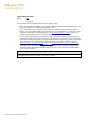
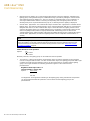
General
DLR/S 8.16.1M | 2CDC 507 100 D0202 3
1 General
The ABB i-bus
®
KNX DALI Light Controller DLR/S combines both the internationally standardized and
open standards for digital illumination control DALI (EN 62 386) and the installation system KNX
(ISO/IEC 14 543-3 and EN 50 090) and, at the same time, allows energy-efficient, constant light control.
Up to 64 DALI devices can be connected to DALI output of the DLR/S. The 64 DALI devices can be
individually addressed and allocated as required in up to 16 lighting groups. Control using KNX is
implemented exclusively via these 16 lighting groups.
With eight light sensors, up to eight separate constant light controls are possible that additionally provide
enhanced comfort and automatic energy conservation.
Constant light control can:
reduce operating costs
save energy
guarantee an optimum working environment at constant brightness
provide enhanced lighting comfort in day-to-day operation
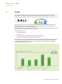
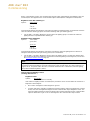
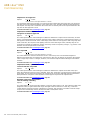
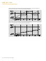
The occupancy is also automatically detected in addition to lighting control via a KNX presence detector,
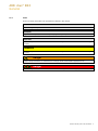
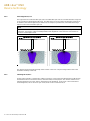
an above average energy saving potential can also be achieved using KNX lighting technology alone.
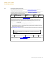
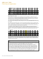
The following graphic provides an overview of the energy that can be saved by the use of modern,
automatic intelligent installation systems.

ABB i-bus
KNX
General
4 2CDC 507 100 D0202 | DLR/S 8.16.1M
1.1 Using the product manual
This manual provides detailed technical information relating to the function, installation and programming
of the ABB i-bus
®
KNX DALI Light Controller DLR/S 8.16.1M and the corresponding Light Sensor LF/U 2.1.
The use of the DLR/S is explained using examples.
This manual is divided into the following chapters:
Chapter 1
General
Chapter 2
Device technology
Chapter 3
Start-up
Chapter 4
Planning and application
Chapter A
Appendix
1.1.1 Structure of the product manual
In this manual, you will find all the descriptions of the parameters and communication objects as well as
application examples.
For the actual configuration of the DALI system, you will require the Software Tool. This Software Tool is
designed exclusively for working with ABB i-bus
®
KNX devices. A description can be found in the online
help of the Tool.
1.1.1.1 Software Tool
A Software Tool is available for DALI commissioning (changing DALI short addresses and DALI group
assignment).
This Software Tool can be downloaded free of charge from our website (www.abb.com/knx).
Other test and analysis functions are also available, depending on the gateway version.
In addition, the Software Tool can be used for simplified setting of the control parameters for constant light
control in the DALI Light Controller. No ETS is required for the Software Tool. However, Falcon Runtime
(version 1.6 or higher and version 1.8 or higher for Windows 7) must be installed to set up a connection
between the PC and KNX.
Note
When the Software Tool is connected to the DALI Light Controller, the function of the DALI devices is, at
first, not influenced. Only when you switch to the configuration mode are the functions, such as
Staircase lighting, Slave and Control, deactivated.
The Block and Forced operation functions are by-passed, meaning that the DALI devices can be
identified clearly for commissioning. However, the Block and Forced operation functions remain in the
background and are reactivated on exiting the Software Tool. Nonetheless, the brightness value set in
the Software Tool remains intact if Forced operation or Block is present. During the connection to the
Software Tool, incoming KNX telegrams are executed. This also applies to the Staircase lighting, Slave
and Control functions. The functions are deactivated again when the Software Tool is exited or when
the DALI device is selected again in the Software Tool.

ABB i-bus
KNX
General
DLR/S 8.16.1M | 2CDC 507 100 D0202 5
1.1.2 Notes
Notes and safety instructions are represented as follows in this manual:
Note
Tips for usage and operation
Examples
Application examples, installation examples, programming examples
Important
These safety instructions are used as soon as there is danger of a malfunction without risk of damage
or injury.
Attention
These safety instructions are used as soon as there is danger of a malfunction without risk of damage
or injury.
Danger
These safety instructions are used if there is a danger to life and limb with inappropriate use.
Danger
These safety instructions are used if there is an extreme danger to life with inappropriate use.

ABB i-bus
KNX
General
6 2CDC 507 100 D0202 | DLR/S 8.16.1M
1.2 Product and functional overview
The group-oriented ABB i-Bus
®
KNX DALI Light Controller DLR/S 8.16.1M is a modular installation device
in ProM design. Up to 64 DALI devices can be connected to a DALI output and can be controlled in
16 lighting groups. The DALI power source for the 64 DALI devices is integrated into the DLR/S.
Control using KNX is implemented exclusively via 16 lighting groups. Only the first 8 lighting groups can be
used for direct constant light control combined with 8 Light Sensors LF/U 2.1. Using the Slave function,
any number of lighting groups can be assigned to a master, e.g. controller. A brightness value offset is
available for a slave, e.g. a second lamp strip, to control a brightness value that deviates from the master
for every controller group (master). The offset can, for example, be time-controlled or switched off or on
with KNX using an outdoor brightness sensor, so that the room is always lit with the optimum level of
brightness. Furthermore, the Staircase lighting function is available. As an option, constant light control
can be combined with the Staircase lighting function.
Furthermore, setting of 14 light scenes is possible, which can be recalled or stored via 8 bit or 1 bit KNX
telegrams.
The DALI devices connected to the DALI output (max. 64) can also be controlled or polled (broadcast)
together. This is also possible without previous commissioning (group assignment) via the KNX.
Information relating to a lamp and/or ballast fault is available individually for a lighting group or for a DALI
device on the KNX. DALI fault messages can be disabled on the KNX with the assistance of a KNX
communication object. Because of this disabling, the DLR/S can, for example, work together with the
emergency lighting monitoring systems which disconnect the lamps from the DALI during an emergency
lighting test. The resulting system-related ballast malfunction detected by the DLR/S is not reported.
Individual lighting groups can be switched or dimmed using manual control on the device. Furthermore,
errors/faults in the lighting group are displayed.
The brightness value (0…100 %) of the ballast after ballast supply voltage recovery (power-on level) can
be parameterized. The initial DALI address assignment occurs automatically via the DALI Light Controller.
For this, when a DALI device is replaced and there is seamless DALI addressing, the new DALI device can
be commissioned automatically without any aids. This function can be suppressed by a parameter in the
application.
Readdressing of the DALI devices and the assignment of the 64 DALI devices into 16 lighting groups is
implemented in the independent Software Tool, so that, for example, a facility manger without ETS
knowledge is capable of exchanging and reassigning DALI devices should maintenance be required.
Fault states of the individual DALI devices and/or lighting groups are represented graphically. Furthermore,
commissioning of the constant light control is simplified. DALI addresses and group assignments can be
deleted and DALI devices reset to their supplied state.
The setting of the parameters and allocation of the group addresses is implemented with the Engineering
Tool Software ETS. The most up-to-date version should be used.

ABB i-bus
KNX
General
DLR/S 8.16.1M | 2CDC 507 100 D0202 7
The application offers a wide range of functions:
Switching, dimming, setting of brightness values including status feedbacks
Programming of individual maximum and minimum dimming limit values (dimming thresholds)
Status response of lamps and/or ballast malfunctions
Coded error checks for each of the individual 64 DALI devices
Different dimming speeds for switching, setting brightness and dimming
Reaction on DALI and KNX bus voltage failure and recovery
Programming of the brightness value (power on level) after a ballast supply voltage recovery
Individual burn-in of lighting groups
Block function and Forced operation
Internal master/slave control in the DLR/S or via communication object
For every Light Controller, a brightness offset that can be activated for a second light strip via KNX
14 independent light scenes, which can be recalled or stored via 1 bit or 8 bit telegrams
Staircase lighting function including warning

ABB i-bus
KNX
General
8 2CDC 507 100 D0202 | DLR/S 8.16.1M
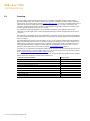
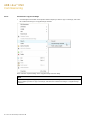
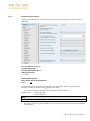
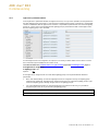
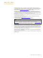
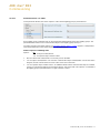
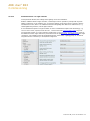
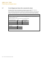
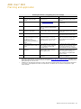
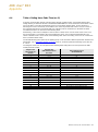
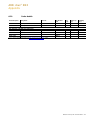
1.3 DALI principles for the DLR/S
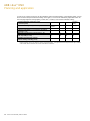
ABB Stotz Kontakt GmbH currently has 4 KNX-DALI devices in the ABB i-bus
®
KNX range, for the
integration of DALI interfaces in a KNX building installation. Independent of additional functions such as
constant light control, every device has its strengths, which become obvious with the different project
types.
The following table shows the fundamental technical differences between the DALI controls. This manual
deals primarily with group-oriented DALI control that is supported in the DLR/S. A detailed description of
the DALI Gateway DG/S specific functions can be found in the product manuals of the DALI Gateway.
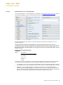
Property
DG/S 8.1
Central
control
DG/S 1.1
Individual
control
DG/S 1.16.1
Group
control
DGN/S 1.16.1
Group
control
DLR/S 8.16.1M
Group
control
DLR/A 4.8.1.1
Group
control
Design
MDRC
MDRC
MDRC
MDRC
MDRC
SM
Mounting width
(1 space unit = 18 mm)
6 units
4 units
4 units
4 units
6 units
220 x 147 x 50 mm
DALI outputs
8 (A…H)
2 (A, B)
1 (A)
1 (A)
1 (A)
1 (A)
Light Sensor (LF/U 2.1)
inputs
-
-
-
-
8
4
DALI equipment (ballast) per
gateway (IEC62386-101)
128 (max. 16 per
output)
128 (max. 64 per
output)
64
64 (ballasts and
emergency lighting
converter)
64
64
DALI emergency lighting
converter (IEC62386-202)
-
-
-
64
-
-
Lighting groups per Gateway
8 (installation)
A: max. 255 (KNX)
B: 1
16
1)
(DALI)
16 (DALI)
16 (DALI)
8 (DALI)
Lighting groups
established via
cable installation
A: KNX
B: Cable
installation
DALI
DALI
DALI
DALI
DALI devices (e.g. ballasts)
per lighting group
max. 16
A: 64 max.
B: 64 max.
max. 64
max. 64
max. 64
max. 64
DALI addressing
not required
A: 64 Individual
B: 64 individual
64 individual
64 individual
64 individual
64 individual
Number of DALI telegrams
per KNX telegram of the
group
1 telegram
A: max. 64
telegrams
B: 1 telegram
1 telegram per
group
1 telegram per
group
1 telegram per
group
1 telegram per
group
Power supply to KNX
processor
2)
via
KNX
KNX
KNX
KNX
KNX
KNX
DALI voltage
3)
integrated power
supply
integrated power
supply
integrated power
supply
integrated power
supply
integrated power
supply
integrated power
supply
1)
Overlapping DALI groups are supported, i.e. a DALI device may belong to several DALI groups.
2)
KNX programming is possible when KNX voltage is connected. Gateway operating voltage for KNX programming is not
required.
3)
A Gateway supply voltage (85…265 V AC or 110…240 V DC) is prerequisite.

ABB i-bus
KNX
General
DLR/S 8.16.1M | 2CDC 507 100 D0202 9
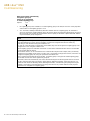
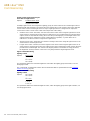
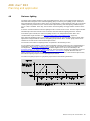
1.3.1 DALI group control
The ABB i-bus
®
KNX DALI Light Controller DLR/S 8.16.1M provides the option of individually addressing
64 DALI devices on a DALI output and making them available via 16 lighting groups on the KNX.
The advantage of this concept is that, at any time, the 64 DALI devices can be assigned to a lighting group
individually and without a change to the installation. As a result, maximum flexibility is retained until final
acceptance or when the room usage changes. At the same time, the programming effort in ETS is
considerably reduced by the assignment of 64 individual devices to 16 lighting grouplighting groups.
Furthermore, the programming effort can also be reduced using the copy and exchange function of lighting
groups in the DLR/S.
The Light Sensors LF/U 2.1 required for constant light control can be assigned to one of the first 8 DALI
lighting groups via ETS. The detected brightness is used in the DALI Light Controller for the calculation of
the control values. The calculated control value is sent directly, without any additional KNX bus
communication, to the assigned DALI lighting group. Using master/slave operation, further lighting groups
can be integrated directly in the DLR/S or indirectly via the communication objects on the KNX.
For every lighting group, the DALI Lighting Controller can send the status of the lighting group on the KNX.
Furthermore, it is possible to poll the fault status of every single DALI device individually via the KNX.
Coded telegrams are available for this purpose.

ABB i-bus
KNX
General
10 2CDC 507 100 D0202 | DLR/S 8.16.1M
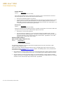
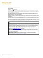
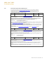
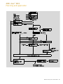
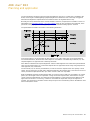
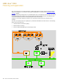
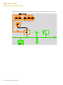
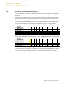
The following diagram clarifies the function of the group-oriented DALI Light Controller DLR/S 8.16.1M:
Note
There is always the possibility of integrating a lamp (DALI device) in several lighting groups. In this
case, we refer to several overlapping lighting groups. The DLR/S does not forcibly inhibit this option.
However, these overlapping lighting groups are not specially supported. There are also no special
parameterization options. The reaction of the overlapping lighting groups is not defined.
It is not recommended, especially with constant light control, to use overlapping lighting groups. The
control circuits should not mutually influence one another or be influenced by an unknown external
controller. In these cases, unsteady, incorrect or highly fluctuating constant light control can result.

ABB i-bus
KNX
Device technology
DLR/S 8.16.1M | 2CDC 507 100 D0202 11
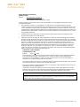
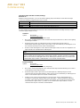
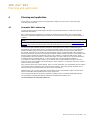
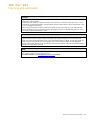
2 Device technology
DLR/S 8.16.1M
LF/U 2.1
The ABB i-bus
®
KNX DALI Light Controller DLR/S 8.16.1M is a KNX modular
installation device (MDRC) in ProM design for installation in the distribution board on
a 35 mm mounting rail.
The DALI Light Controller can, in conjunction with the application program Control
Dim Groups 8f DALI/1, integrate devices with DALI interfaces into a KNX building
installation. The connection to the KNX is implemented via a KNX connection
terminal on the device shoulder.
The 8 sensor inputs for the Light Sensor LF/U, together with the first 8 lighting
groups of the DALI Light Controller, can be used for a constant light control.
Up to 64 DALI devices can be connected to the DALI output. The 64 DALI devices
should be assigned to 16 lighting groups with the ETS-independent Software Tool.
Control of the 64 DALI devices via KNX is exclusively group-oriented.
The fault status (lamps and ballasts) of every individual DALI device can be sent via
a coded communication object on the KNX.
In the DLR/S, a staircase lighting time curve can be set. Constant light control can
be combined with a staircase lighting time curve, so that constant light control can
be implemented during the staircase lighting time curve. The 16 lighting groups can
be integrated into scenes as required. Using 1 bit or 8 bit KNX scene telegrams,
these scenes can then be recalled or stored via the KNX. Furthermore, a
Master/Slave function with integrated offset is available that can be used to integrate
further lighting groups or dimming actuators into the light control.
Using central telegrams, all the DALI devices connected to a DALI output can be
commonly controlled via the KNX (broadcast).
The DLR/S is a DALI control device (master) and requires an AC or DC auxiliary
power supply. The DALI power source for the 64 DALI devices is integrated into the
DALI Light Controller. In order to control the DALI devices manually or via the KNX,
the KNX voltage and the auxiliary voltage (light controller operating voltage) must be
applied. Should one of these voltage sources be absent, the DALI devices can no
longer be controlled. The reaction of the DALI devices on voltage failure can be
parameterized.
Individual lighting groups can be switched or dimmed using manual control on the
device. Furthermore, the fault for every lighting group is indicated by a yellow LED
on the DLR/S.
2CDC 071 076
S0009
2CDC 071 018 F0008

ABB i-bus
KNX
Device technology
12 2CDC 507 100 D0202 | DLR/S 8.16.1M
2.1 DLR/S 8.16.1M
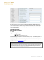
2.1.1 Technical data DLR/S 8.16.1M
Supply
Light controller supply voltage
85…265 V AC, 50/60 Hz
110…240 V DC
Power consumption total via mains
Maximum 3.5 W at 230 V AC and max. load
1)
Current consumption total via mains
Maximum 15 mA at 230 V AC and max. load
1)
Leakage loss total for device
Maximum 1.6 W at 230 V AC and max. load
1)
Current consumption KNX
Maximum 10 mA
Power consumption via KNX
Maximum 210 mW
DALI output
Number of outputs
1 to EN 60 929 and DIN EN 62 386
The DALI output is a fixed 230 V, i.e.
unintentional application of the light controller
supply voltage will not cause destruction of the
DALI output.
Number of DALI devices
Maximum 64
Number of lighting groups
16
Distance between DLR/S and last DALI device
Cable cross-section 0.50 mm
2
0.75 mm
2
1.00 mm
2
1.50 mm
2
100 m
2)
150 m
2)
200 m
2)
300 m
2)
Sensor inputs
Light Sensor LF/U 2.1
Number of inputs
Max. cable length per sensor
For detailed information,
see Light Sensor LF/U 2.1, page 18
8
Per light sensor 100 m, Ø 0.8 mm,
P-YCYM or J-Y(ST)Y cable (SELV),
e.g. shielded KNX bus cable
Connections
KNX
KNX connection terminal,
0.8 mm Ø, solid
DALI outputs and mains voltage
Screw terminal:
0.2…2.5 m
m2
fine stranded
0.2…4 mm
2
single core
Tightening torque
Max. 0.6 Nm
Light Sensor LF/U:
Wire end ferrule without/with plastic sleeve
TWIN ferrule
Tightening torque
Without 0.25…2.5 mm
2
/ with 0.25…4 mm
2
0.5…2.5 mm
2
Max. 0.6 Nm
Brightness detection
Lighting control operating range
Optimized for 500 Lux.
200…1,200 Lux for rooms with average
furnishing level, degree of reflection 0.5
Max. 860 Lux in a very brightly furnished room
(reflection 0.7)
Max. 3,000 Lux in a very darkly furnished room
(reflection 0.2)
The Lux values are measured values on the
work surface (reference surface)
3)
.

ABB i-bus
KNX
Device technology
DLR/S 8.16.1M | 2CDC 507 100 D0202 13
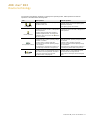
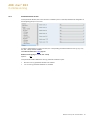
Operating and display elements
Button/LED
For assignment of the physical address
Button /LED
For switchover between manual operation and
KNX operation
Button
Switch to next lighting group
Button
Switch ON or dim UP
Button
Switch OFF or dim DOWN
Button
Detect devices
LED
Display for operation readiness
LED
DALI operating voltage display
16 LED …
Lighting group 1…16 display
Degree of protection
IP 54
Compliant to EN 60 529
Protection class
II
Compliant to EN 61 140
Isolation category
Overvoltage category
Pollution degree
III to EN 60 664-1
2 to EN 60 664-1
KNX safety extra low voltage
SELV 24 V DC
DALI voltage
Typical 16 V DC (9.5…22.5 V DC)
No-load voltage
Lowest supply current at 11.5 V
Highest supply current
To DIN EN 60 929 and DIN EN 62 386
16 V DC
4)
160 mA
230 mA
Temperature range
Power
-5 °C…+45 °C
Storage
-25…+55 °C
Transport
-25…+70 °C
Environmental conditions
Humidity
Maximum 95 %, no condensation allowed
Design
Modular installation device (MDRC)
Modular installation device, ProM
Dimensions
90 x 108 x 64.5 mm (H x W x D)
Mounting width
6 x 18 mm modules
Mounting depth
68 mm
Mounting
On 35 mm mounting rail
Compliant to EN 60 715
Installation position
Any
Weight
0.26 kg
Housing, color
Plastic housing, gray
Approvals
KNX to EN 50 090-1, -2
EN 62 386 (Part 101 and 102)
Certification
DALI
CE mark
In accordance with the EMC guideline and low
voltage guideline
1)
Maximum load corresponds to 64 DALI devices at 2 mA each.
2)
The length relates to the entire routed DALI control cable.
The maximum values are rounded off and relate to the resistance value. EMC influences are not considered. For this reason, the values should be
considered as absolute maximum values.
3)
Rooms are lit up differently by the incidental daylight and the artificial light of the lamps. Not all the surfaces in the rooms, e.g. walls, floor and
furniture, reflect the light which falls on them in the same manner. Accordingly, even though there is an exactly calibrated constant light control in
daily operation, deviations to the setpoint value may occur. These deviations may be up to +/- 100 lx, should the current ambient conditions in the
room, and accordingly the reflection properties of the surfaces (paper, people, reorganized or new furniture), differ significantly from the original
ambient conditions at the time of calibration. Deviations may also occur if the light sensor is influenced by direct or reflected light falling on it, which
is not influenced or only slightly influenced by the surfaces in the detection range of the light sensor.
4)
Cannot be measured directly on the digital multimeter, as there is not a constant DC voltage due to the DALI telegrams. Measure with a CRO for
correct results. One exception is the KNX download phase. In this phase, no DALI telegrams are sent, whereby the DALI voltage is constantly
present on the DALI output.

ABB i-bus
KNX
Device technology
14 2CDC 507 100 D0202 | DLR/S 8.16.1M
Note
The DALI gateway conforms to the SELV properties to IEC 60 364 4 41 (DIN VDE 0100 410).
DALI does not need to feature SELV properties, and it is possible to route the DALI control lines
together with the mains voltage on a multi-core cable.
All-pole disconnection must be ensured in order to avoid dangerous touch voltages which originate from
feedback from differing phase conductors.
Installation must be performed so that both DALI lines and lines carrying mains voltage are
disconnected when an area is disconnected.
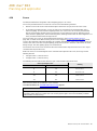
Device type
Application
Max. number of
communication objects
Max. number of
group addresses
Max. number of
associations
DLR/S 8.16.1M
Control Dim Groups 8f DALI/1*
212
254
255
* … = Current version number of the application. Please refer the software information on our website for this purpose.
Note
ETS and the current version of the device application are required for programming.
Editing with the ETS2 is not possible!
The current application can be found with the respective software information for download on the
Internet at www.abb.com/knx. After the import to the ETS, the application can be found at
ABB/Illumination/Light Controller/Control Dim Groups 8f DALI/1.
The device does not support the locking function of a KNX device in ETS. If you use a BCU code to
inhibit access to all the project devices, it has no effect on this device. Data can still be read and
programmed.

ABB i-bus
KNX
Device technology
DLR/S 8.16.1M | 2CDC 507 100 D0202 15
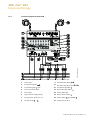
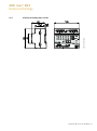
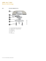
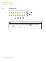
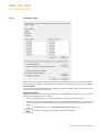
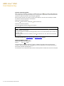
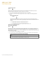
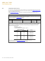
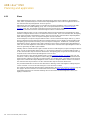
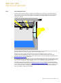
2.1.2 Connection diagram DLR/S 8.16.1M
1
Label carrier
9
LED Operation display
2
Programming button
10
LED DALI operating voltage
3
Programming LED (red)
11
LED Manual operation
4
Bus connection terminal
12
Manual operation button
5
DALI output
13
Groups button
6
Light controller supply voltage
14
Detect devices button
7
8 Light Sensor inputs LF/U 2.1
15
Button ON/UP OFF/DOWN
8
16 LED groups …
16
Light Sensor LF/U 2.1
2CDC 072 024 F0011

ABB i-bus
KNX
Device technology
16 2CDC 507 100 D0202 | DLR/S 8.16.1M
Note
When positioning the Light Sensor LF/U in the room, it is important to ensure that the individual control
circuits cannot interfere with one another. The LF/U should be mounted above the area, in which the
actual lighting intensity is measured.
The luminaires or sunlight may not shine directly into the brightness sensor. Pay attention to
unfavorable reflections, for example, from mirrored or glass surfaces.
The white fibre-optic rod can limit the detection range and reduce the lateral lighting sensitivity to
external lighting sources.
Note
If the LF/U is not connected to the DLR/S, a DC voltage of a few mV can be measured directly with a
multi-function measurement device. The measured value is between 0 mV (absolute darkness) and a
few 100 mV, depending on the brightness. If 0 mV is also measured at normal brightness, this is due to
an open circuit, short circuit or inverse polarity fault or a defective sensor.

ABB i-bus
KNX
Device technology
DLR/S 8.16.1M | 2CDC 507 100 D0202 17
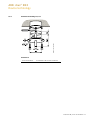
2.1.3 Dimensional drawing DLR/S 8.16.1M
2CDC 072 002 F0011

ABB i-bus
KNX
Device technology
18 2CDC 507 100 D0202 | DLR/S 8.16.1M
2.2 Light Sensor LF/U 2.1
LF/U 2.1
The ABB i-bus
®
KNX Light Sensor LF/U 2.1 is a brightness sensor for closed rooms.
The Light Sensor is installed in a standard installation box in the ceiling. The cover (white)
of the sensor is stuck firmly onto the device. The complete unit is then screwed into a
flush-type box.
Up to eight Light Sensors LF/U 2.1 can be connected to a DALI Light Sensor
DLR/S 8.16.1M. The Light Sensor measures brightness values in closed rooms. When
combined with the detected values, the DLR/S is used for constant light control. It is
possible to combine the brightness values from several Light Sensors for the calculation of
an individual control circuit. It is thus possible to implement light control in rooms with
difficult lighting conditions.
The electrical connection of the LF/U to the DLR/S is undertaken with a twin core MSR
cable (SELV), e.g. KNX bus cable. The total length of this cable may not exceed 100 m.
The LF/U is supplied with a Plexiglas rod, which snaps into the sensor housing.
The registration area can be limited with the Plexiglas rod with the white coating.
2.2.1 Technical data LF/U 2.1
Supply
SELV
Implemented via DLR/S 8.16.1M
Connections
On the DLR/S 8.16.1M
1 connecting terminal white/yellow
(connecting terminals are supplied with the
device)
Max. cable length per sensor
Per sensor 100 m, Ø 0.8 mm,
P-YCYM or J-Y(ST)Y cable (SELV),e.g.
shielded KNX bus cable
Brightness detection
Lighting control operating range
Optimized for 500 Lux.
200…1,200 Lux for rooms with average
furnishing level, degree of reflection 0.5
Max. 860 Lux in a very brightly furnished room
(reflection 0.7)
Max. 3,000 Lux in a very darkly furnished room
(reflection 0.2)
The Lux values are measured values on the
work surface (reference surface)
1)
.
Optimum installation height
2…3 m
Degree of protection
IP 20
To EN 60 529
Protection class
II
To EN 61 140
Isolation category
Overvoltage category
Pollution degree
III to EN 60 664-1
2 to EN 60 664-1
2CDC 071 018 F0008
Page is loading ...
Page is loading ...
Page is loading ...
Page is loading ...
Page is loading ...
Page is loading ...
Page is loading ...
Page is loading ...
Page is loading ...
Page is loading ...
Page is loading ...
Page is loading ...
Page is loading ...
Page is loading ...
Page is loading ...
Page is loading ...
Page is loading ...
Page is loading ...
Page is loading ...
Page is loading ...
Page is loading ...
Page is loading ...
Page is loading ...
Page is loading ...
Page is loading ...
Page is loading ...
Page is loading ...
Page is loading ...
Page is loading ...
Page is loading ...
Page is loading ...
Page is loading ...
Page is loading ...
Page is loading ...
Page is loading ...
Page is loading ...
Page is loading ...
Page is loading ...
Page is loading ...
Page is loading ...
Page is loading ...
Page is loading ...
Page is loading ...
Page is loading ...
Page is loading ...
Page is loading ...
Page is loading ...
Page is loading ...
Page is loading ...
Page is loading ...
Page is loading ...
Page is loading ...
Page is loading ...
Page is loading ...
Page is loading ...
Page is loading ...
Page is loading ...
Page is loading ...
Page is loading ...
Page is loading ...
Page is loading ...
Page is loading ...
Page is loading ...
Page is loading ...
Page is loading ...
Page is loading ...
Page is loading ...
Page is loading ...
Page is loading ...
Page is loading ...
Page is loading ...
Page is loading ...
Page is loading ...
Page is loading ...
Page is loading ...
Page is loading ...
Page is loading ...
Page is loading ...
Page is loading ...
Page is loading ...
Page is loading ...
Page is loading ...
Page is loading ...
Page is loading ...
Page is loading ...
Page is loading ...
Page is loading ...
Page is loading ...
Page is loading ...
Page is loading ...
Page is loading ...
Page is loading ...
Page is loading ...
Page is loading ...
Page is loading ...
Page is loading ...
Page is loading ...
Page is loading ...
Page is loading ...
Page is loading ...
Page is loading ...
Page is loading ...
Page is loading ...
Page is loading ...
Page is loading ...
Page is loading ...
Page is loading ...
Page is loading ...
Page is loading ...
Page is loading ...
Page is loading ...
Page is loading ...
Page is loading ...
Page is loading ...
Page is loading ...
Page is loading ...
Page is loading ...
Page is loading ...
Page is loading ...
Page is loading ...
Page is loading ...
Page is loading ...
Page is loading ...
Page is loading ...
Page is loading ...
Page is loading ...
Page is loading ...
Page is loading ...
Page is loading ...
Page is loading ...
Page is loading ...
Page is loading ...
Page is loading ...
Page is loading ...
Page is loading ...
Page is loading ...
Page is loading ...
Page is loading ...
Page is loading ...
Page is loading ...
Page is loading ...
Page is loading ...
Page is loading ...
Page is loading ...
Page is loading ...
Page is loading ...
Page is loading ...
Page is loading ...
Page is loading ...
Page is loading ...
Page is loading ...
Page is loading ...
Page is loading ...
Page is loading ...
Page is loading ...
Page is loading ...
Page is loading ...
Page is loading ...
Page is loading ...
Page is loading ...
Page is loading ...
Page is loading ...
Page is loading ...
Page is loading ...
Page is loading ...
Page is loading ...
Page is loading ...
Page is loading ...
Page is loading ...
Page is loading ...
Page is loading ...
Page is loading ...
Page is loading ...
Page is loading ...
Page is loading ...
Page is loading ...
Page is loading ...
Page is loading ...
Page is loading ...
Page is loading ...
Page is loading ...
Page is loading ...
Page is loading ...
Page is loading ...
Page is loading ...
Page is loading ...
Page is loading ...
Page is loading ...
Page is loading ...
Page is loading ...
Page is loading ...
Page is loading ...
Page is loading ...
Page is loading ...
Page is loading ...
Page is loading ...
Page is loading ...
Page is loading ...
Page is loading ...
Page is loading ...
-
 1
1
-
 2
2
-
 3
3
-
 4
4
-
 5
5
-
 6
6
-
 7
7
-
 8
8
-
 9
9
-
 10
10
-
 11
11
-
 12
12
-
 13
13
-
 14
14
-
 15
15
-
 16
16
-
 17
17
-
 18
18
-
 19
19
-
 20
20
-
 21
21
-
 22
22
-
 23
23
-
 24
24
-
 25
25
-
 26
26
-
 27
27
-
 28
28
-
 29
29
-
 30
30
-
 31
31
-
 32
32
-
 33
33
-
 34
34
-
 35
35
-
 36
36
-
 37
37
-
 38
38
-
 39
39
-
 40
40
-
 41
41
-
 42
42
-
 43
43
-
 44
44
-
 45
45
-
 46
46
-
 47
47
-
 48
48
-
 49
49
-
 50
50
-
 51
51
-
 52
52
-
 53
53
-
 54
54
-
 55
55
-
 56
56
-
 57
57
-
 58
58
-
 59
59
-
 60
60
-
 61
61
-
 62
62
-
 63
63
-
 64
64
-
 65
65
-
 66
66
-
 67
67
-
 68
68
-
 69
69
-
 70
70
-
 71
71
-
 72
72
-
 73
73
-
 74
74
-
 75
75
-
 76
76
-
 77
77
-
 78
78
-
 79
79
-
 80
80
-
 81
81
-
 82
82
-
 83
83
-
 84
84
-
 85
85
-
 86
86
-
 87
87
-
 88
88
-
 89
89
-
 90
90
-
 91
91
-
 92
92
-
 93
93
-
 94
94
-
 95
95
-
 96
96
-
 97
97
-
 98
98
-
 99
99
-
 100
100
-
 101
101
-
 102
102
-
 103
103
-
 104
104
-
 105
105
-
 106
106
-
 107
107
-
 108
108
-
 109
109
-
 110
110
-
 111
111
-
 112
112
-
 113
113
-
 114
114
-
 115
115
-
 116
116
-
 117
117
-
 118
118
-
 119
119
-
 120
120
-
 121
121
-
 122
122
-
 123
123
-
 124
124
-
 125
125
-
 126
126
-
 127
127
-
 128
128
-
 129
129
-
 130
130
-
 131
131
-
 132
132
-
 133
133
-
 134
134
-
 135
135
-
 136
136
-
 137
137
-
 138
138
-
 139
139
-
 140
140
-
 141
141
-
 142
142
-
 143
143
-
 144
144
-
 145
145
-
 146
146
-
 147
147
-
 148
148
-
 149
149
-
 150
150
-
 151
151
-
 152
152
-
 153
153
-
 154
154
-
 155
155
-
 156
156
-
 157
157
-
 158
158
-
 159
159
-
 160
160
-
 161
161
-
 162
162
-
 163
163
-
 164
164
-
 165
165
-
 166
166
-
 167
167
-
 168
168
-
 169
169
-
 170
170
-
 171
171
-
 172
172
-
 173
173
-
 174
174
-
 175
175
-
 176
176
-
 177
177
-
 178
178
-
 179
179
-
 180
180
-
 181
181
-
 182
182
-
 183
183
-
 184
184
-
 185
185
-
 186
186
-
 187
187
-
 188
188
-
 189
189
-
 190
190
-
 191
191
-
 192
192
-
 193
193
-
 194
194
-
 195
195
-
 196
196
-
 197
197
-
 198
198
-
 199
199
-
 200
200
-
 201
201
-
 202
202
-
 203
203
-
 204
204
-
 205
205
-
 206
206
-
 207
207
-
 208
208
-
 209
209
-
 210
210
-
 211
211
-
 212
212
-
 213
213
-
 214
214
-
 215
215
-
 216
216
-
 217
217
-
 218
218
-
 219
219
-
 220
220


Ask a question and I''ll find the answer in the document
Finding information in a document is now easier with AI
Related papers
-
ABB i-bus KNX User manual
-
-
-
-
-
-
-
-
-
Other documents
-
Dataflex 54.500 Datasheet
-
Sunricher SR-2701B User manual
-
THEBEN DU 1 DALI S RF KNX User manual
-
iGuzzini MI27 Installation guide
-
-
-
-
-
-
Dali Wall bracket Operating instructions