FS Fotr Series Handheld Optical Time Domain Reflectometer User guide

Type
User guide
Optical Time Domain Reectometer
MENU Marker File OPM VFL
ESC
REAL
SCAN
CHARGE
ENTER
FOTR SERIES HANDHELD OPTICAL
TIME DOMAIN REFLECTOMETER
V1.0
Quick Start Guide
Quick-Start Anleitung
Guide de Démarrage Rapide
TRAGBARE OPTISCHE ZEITBEREICHSREFLEKTOMETRIE
OTDR DER FOTRSERIE
RÉFLECTOMÈTRE OPTIQUE TEMPOREL DE POCHE DE
LA SÉRIE FOTR
EN
Optical Time Domain Reectometer
MENU Marker File OPM VFL
ESC
REAL
SCAN
CHARGE
ENTER
Introduction
The FOTR series Handheld OTDR is designed to meet a wide variety of
requirements for the optical ber measurement in short and medium distance. It
has outstanding performance at the event dead zone and dynamic range. The
built-in VFL can guarantee the fault detection for all range optical bers.
FOTR-201/FOTR-202/FOTR-203
USB Cable x1 Power Adapter x1
FOTR-201/FOTR-202/FOTR-203
Accessories
1
EN
Optical Time Domain Reectometer
MENU Marker File OPM VFL
ESC
REAL
SCAN
CHARGE
ENTER
Function Introductions
1 2 3
USB Micro SD DC
4
5
10
11
12
13
17
14
18 15
16
19 20 21
6
7
8
9
2
EN
24
2322
OTDR
FC/PC
VFL
FC/PC
NO. Description
1
2
3
USB interface
TF(micro SD) card slot
Power adapter socket
4Charge Indicator
5
6
7
8
9
10
11
Cursor select button
Menu button
Zoom control button
Full screen button
Power button
LCD
File operation button
3
EN
NO. Description
12
13
14
OPM fast enter button
VFL control button
Cancel button
15 Real-time measurement button
16
17
18
19
20
21
22
23
24
Average measurement button
Up button
Conrming button
Left button
Down button
Right button
OTDR optic ber connector
VFL optic ber connector
Anti-dust cover
4
EN
Operation Instructions
1. On/o
Button is used to turn on/o the device. Keep pressing it for 2 seconds to
turn on device. Short press it again to turn o the device.
Press " " button to start measuring. But user should modify measurement
setting by real requirement before test start.
SCAN
2. Measurement Interface
There are 10x10 grids in waveform region. Horizontal grids mean distance, vertical
grids mean dB value. As shown in gure, each horizontal grid represents 0.2km,
each vertical grid represents 4dB.
2012-01-01 WED 21:25
*
A-B: ---.---Km --.--dB --.--dB/Km Km/div
File Info:
No. Distance Loss Reection dB/Km C.Loss
2012-01-01
B: 0.000Km
WED 21:25
174622_0001.sor
0.00
4.00
8.00
12.00
16.00
20.00
24.00
28.00
32.00
36.00
40.00
A-B: 000.000Km 00.00dB 00.00dB/Km 0.200Km/div
Measure Info;
1/3
No. Distance Loss Reection dB/Km C.Loss
0.000 0.00 0.00-28.00 - -.- -
1550nm 2.0Km 10ns
Power
Date and time
The distance and
Attenuation between
A and B cursor
File name
Waveform region
Every horizontal grid
is 0.2Km
Events list
Measurement setting
info
5
EN
Optic ber start Reection event Attenuation event
Mix event Gain event Optic ber ending
Press Up or Down button to select an event which needs to be located by cursor
on the waveform. Then press " " button to return to waveform interface. The
cursor will stay on the position of the selected event. Press " " button to return
to waveform interface.
3. Real-time and average measurement
Real-time measurement can quickly judge basic faults of optical ber. Press " "
button to start real-time measuring. During measuring, you can change range,
zoom in or zoom out . Press " " button again or " " button to stop.
The device will not analyses event after real-time measure-ment in default. Unless
you turn on RT analyse in System settings, the device will analyse events
according to the last refreshed waveform.
Average measurement can judge the line condition more accurate. It can get a
better SNR and ts high requirement circuit. Press " " button to start. User can
set measurement time from 5 second to 180 second. The device analyses
events and generates event list automatically. Press " " button during
measuring, device will stop measuring, analyses events and generates event list
automatically.
4. Event list
After measurement or open a waveform in memory, there is event list on the
bottom of waveform interface. Press " " button to show the whole event list.
Six types of events as followed:
REAL
REAL ESC
SCAN
ESC
ENTER
ENTER
ESC
6
EN
5. Real-time measurement tips
The device supports user to change measurement range during real-time
measurement. Start Real-time measuring function and press Up or Down button
to increase or decrease the range. And it also supports to change the cursor
position and zoom in/out waveform in realtime, which means you can zoom in
partial waveform while measuring to judge the network fault.
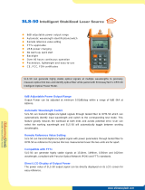
6. Cusor selection and waveform zoom in/out
This device has two cursors, A and B. Default distance is 0m, activated cursor
turned to brightred. Press " " button switch to another cursor. Press Left or
Right button to move cursor. Press Up or Down button to previous or next event.
You can calculate the distance and attenuation between two cursors.
Keep pressing " " , then press and Up/Down button to zoom in or out
waveform vertically.
Keep pressing " " , then press Left/Right button to zoom in or out horizontally.
Press " " button to return to full screen display.
Event List
No.
1/6
4.301 0.12 -54.67 0.28 1.18
0.940 0.08 -51.74 0.24 0.26
0.000 0.00 -51.74 -.-- 0.00
5.589 -.-- -.-- -.-- -.--
18.712 -0.05 -41.03 0.22 4.07
39.809 -.-- -46.02 0.21 9.41
2/6
3/6
4/6
5/6
6/6
Press key ENTER tolocate the corresponding event.
Dis. Loss Ref. dB/Km C.Loss
2012-01-01
A: 0.000Km
WED 21:25
*
0.00
4.00
8.00
12.00
16.00
20.00
24.00
28.00
32.00
36.00
40.00
A-B: 000.000Km 00.00dB 00.00dB/Km 0.200Km/div
Measure Info:
1/3
No. Distance Loss Reection dB/Km C.Loss
0.000 0.00 0.00-28.00 - -.- -
1550nm 2.0Km 10ns
B: 0.583Km
Marker
7
EN
7. Menu
There are four pages of menu which used to congure parameters. Under
waveform interface, press " " button to switch the four menus cyclically.
7.1 Menu-File menu
(1) Enter File menu, there are two options, "open" and "formatting SD card". Select
one option and press " " button to enter the corresponding operation.
File
Open
Format SD Card...
Measure Settings
Press key MENU to switch to the menu tag.
System Settings About
Open...
Format SD Card...
Are you sure to format the SD card?
Warnning
OK Cancel
WARNING: Formatting SD card operation will delete all les
and cannot recover, please be cautious.
MENU
ENTER
8
NOTE: The focus of zooming is the location of the activated cursor.
EN
(2) Select "open" option, there are folders. The folder name is the date of the le
saved, which is generated automatically by system. Files measured in the same
day will be stored in the same folder. Folder can only be delete, but not rename.
And must delete all les before delete the folder.
Press Up or Down button to select a folder and press " " button to open delete
tip. Then press " " button to nish deleting, or press " " or " " button to
cancel.
(3) Select one folder to display all les inside. Press Up or Down button to select
one le and press " " button to display it in main interface. The le information
at the bottom is the le's main measurement setting.
Press " " button can delete or rename the le. Filename can make up of 23
digits, alphabets and special symbols at most. The last four numbers_xxxx is
generated by "Automatic naming" function. Shut down this function will not
generate.
File
20140615 2014-06-15
20140617
20140618
20140619
20140622
2014-06-17
2014-06-18
2014-06-19
2014-06-22
Measure Settings
Press key RIGHT to edit les,press key LEFT to exit.
System Settings About
Delete...
File
.
..
133210_0001.sor
133210_0002.sor
133210_0003.sor
133210_0004.sor
2014-06-18
2014-06-18
2014-06-18
2014-06-18
Measure Settings
File Info: 1550nm 370m 10ns
System Settings About
Delete...
Rename...
ENTER ESC
ENTER
9
EN
(4) When nish measuring an optic ber, press " " button to enter storage
interface. Default lename is hour/minute/second of rst time storage. Press
Up/Down/Left/Right button to select alphabets, digits and symbols on
soft keyboard. You can input 23 alphabets at most. If "Automatic naming" is
enabled, the lename will automatically generated with four digits. Without
shutting down the device, the following stored le's name will automatically
plus 1. The le format is .SOR. On le recalling interface, press Right button can
Modify lename, as the same operations above.
7.2 Menu-Measure settings
Measure settings menu is used to set relative measurement data, which the
judgment of events list is based on. Wrong setting might leads to wrong or
missing events.
Wavelength---wavelength of laser.
Scan mode---manual and auto mode. Under auto mode, it will match the
distance, range and pulse width.
Range---match with the length of measured optic ber, usually over one level.
Pulse width---set the pulse width of output laser. Usually, small pulse width can
measure close event, large pulse width can measure remote distance, but enlarge
event's blind area.
Average time--- can set between 5 second and 180 second as average measure-
ment time.
Splice loss---treat as an event when the loss is higher than setting value.
Rename
File Name:
140950
abcdefg789
hijklmn456
opqrstu123
vwxyz._0 #
backCaps Save
File
10
EN
Reection threshold---treat as an event when the reection is higher than setting
value.
End threshold---treat as the end of optic ber when the loss is higher than setting
value.
Refractive rate---represent the average refractive index of entire optic ber.
Scatter coecient--- the intrinsic value of Rayleigh Scattering.
7.3 Menu-System settings
System settings menu is used to set the device's basic functions.
Auto Power O--- set time of automatic o or cancel this function
Auto Name---name automatically when le is saving, can cancel this function.
Optical Detector --- detect whether there is signal in optic ber or not before
measuring.
RT Analyse --- set whether analyses events after real-time measuring or not.
Brightness--- adjust brightness of LCD.
Date--- set year, month, day.
Time ---set hour, minute.
Length unit --- default is metric units.
Factory settings --- is used in resetting to default , and has no eect on The set
time and stored data.
File
Wavelength
Scan Mode
Range
Pulse Width
Average Time
Splice Loss
Reection Threshold
End Threshold
Refractive Rate
Scatter Coecient
Km
ns
s
dB
dB
dB
dB
Measure Settings System Settings About
nm
1550
Manual
40
1000
120
0.05
65.0
2.0
1.46832
52.1
11
EN
7.4 Menu- About
This menu is version details about device's conguration of hardware and
software. CPU number is used to generate upgrading code, which should inform
distributor or factory before software upgrading.
8. OPM function
Press " " button on device with OPM function to enter OPM measurement
interface. Press " " button to start measuring. Press " " button to change
the wavelength. The meter's six calibration wavelengths are: 850nm, 1300nm,
1310nm, 1490nm, 1550nm, 1625nm. Press " " button to quit OPM function.
File
Firmware Version TEN 1A20V35_MAIN_V1.2
Measure Settings System Settings About
Firmware Version SEN1A20V35_MAIN_V1.2.0
Firmware Version FEN1A20V35_MAIN_V1.x.0
Firmware Version A4B75978
Language English
TEN 1A20V35_ANALOG_V0.3
TEN 1A20V35_TFT_V1.1
File
Auto Power O
Auto Name
Optical Dectector
RT Analyse
Brightness
Date
Time
Length Unit
Factory Settings
Press key ENTER toedit settings.
Measure Settings System Settings About
10min
On
On
O
60
2013 11 02
21 57
Metric
No
Optical Power Meter
Press key Down to change
the wavelength.
dBm
mw
Press key Enter to start or
to stop measure.
Power +00.00
000.00
1310 nm
On
OPM
ENTER
ESC
12
EN
9. VFL
This device has VFL function, the output power is about 1nW. Press " " button
to control red laser on-ashing-o. When Laser is on, the prompt icon will occur at
upper right corner.
10. TF card and USB communication
All measured waveforms are stored in TF card. Using mini USB cable can store
data to PC. PC will show a new disk icon, data inside. According to lename, user
can store or recall les.
2012-01-01
B: 0.000Km
WED 21:25
*
0.00
4.00
8.00
12.00
16.00
20.00
24.00
28.00
32.00
36.00
40.00
A-B: 000.000Km 00.00dB 00.00dB/Km 0.200Km/div
Measure Info;
1/3
No. Distance Loss Reection dB/Km C.Loss
0.000 0.00 0.00-28.00 - -.- -
1550nm 2.0Km 10ns
2012-01-01
B: 0.000Km
WED 21:25
0.00
4.00
8.00
12.00
16.00
20.00
24.00
28.00
32.00
36.00
40.00
A-B: 000.000Km 00.00dB 00.00dB/Km 0.200Km/div
Measure Info;
1/3
No. Distance Loss Reection dB/Km C.Loss
0.000 0.00 0.00-28.00 - -.- -
1550nm 2.0Km 10ns
*
VFL
13
11. User upgrading
When device needs upgrading, user does not need to send it back to factory.
Prepare materials before upgrading as followed:
(1) CPU ID
(2) TF(micro SD) card, capacity is less than 16GB
Inform the CPU ID to distributor or factory, you can get upgrading rmware only
for your device. Store the rmware to TF card through computer. Insert TF card to
device when it is power o.
EN
Press " " and " " button and hold them, then press " " button to turn
on the device, upgrading is starting. You can delete upgrading le in TF card when
nish upgrading.
12. Charging
This device has lithium batteries inside, and can only use the power adapter from
factory to charge it. Insert the adapter to device, and nish charging in 8-10 hours.
Red charge indicator means charging, while green means nish.
Maintenance
(1) You are cautioned that changes or modications not espressly approved in this
document could void yout authority to operate this equipment.
(2) To reduce the risk of re or electric shock,do not expose this apparatus to rain
or moisture.
(3) To avoid electrical shock, do not open the cabinet. Refer servicing to
qualiedpersonnel only.
(4) As the laser is harmful to the eyes, do not attempt to disassemble the cabinet.
(5) At the same time, can not use dierent style or dierent capacitance batteries.
And only charge the rechargeable batteries.
(6) As much as possible, avoid sudden temperature changes. Do not attempt to
use the drive immediately after moving it from a cold to a warm location, to
raising the room temperature suddenly, as condensation may form with in the
drive. If the temperature changes suddenly while using the drive, stop using it
and take out batteries for at least an hour.
(7) When long time no use, must take out the batteries to avoid destroying the
device.
MENU SCAN
14
EN
1
Product Warranty
Online Resources
Download
Help Center
Contact Us
https://www.fs.com/products_support.html
https://www.fs.com/service/fs_support.html
https://www.fs.com/contact_us.html
FS ensures our customers that any damage or faulty items due to our workman-
ship, we will oer a free return within 30 Days from the day you receive your
goods.
Warranty: All Optical Power Meters enjoy 1 year limited warranty
against defect in materials or workmanship. For more details about
warranty, please check at https://www.fs.com/policies/warranty.html
Return: If you want to return item(s), information on how to return
can be found at https://www.fs.com/policies/day_return_policy.html
15
Optical Time Domain Reectometer
MENU Marker File OPM VFL
ESC
REAL
SCAN
CHARGE
ENTER
Einführung
Die tragbare OTDR der FOTR-Serie wurde entwickelt, um eine Vielzahl von
Anforderungen für die Messung von Lichtwellenleitern über kurze und mittlere
Entfernungen zu erfüllen. Sie verfügt über eine hervorragende Leistung bei der
Ermittlung der Deadzone und des Dynamikbereichs. Der eingebaute VFL
ermöglicht eine Fehlererkennung für alle Glasfasern.
FOTR-201/FOTR-202/FOTR-203
USB-Kabel x1 Netzadapter x1
FOTR-201/FOTR-202/FOTR-203
Zubehör
16
DE
Optical Time Domain Reectometer
MENU Marker File OPM VFL
ESC
REAL
SCAN
CHARGE
ENTER
Funktionen
1 2 3
USB Micro SD DC
4
5
10
11
12
13
17
14
18 15
16
19 20 21
6
7
8
9
17
DE
18
24
2322
OTDR
FC/PC
VFL
FC/PC
NR. Beschreibung
1
2
3
USB-Schnittstelle
TF(micro SD)-Kartensteckplatz
Netzadapter-Buchse
4Ladeindikator
5
6
7
8
9
10
11
Cursor-Auswahltaste
Menü-Taste
Taste für die Zoomsteuerung
Taste für Vollbild
Power-Taste
LCD
Taste für Dateibearbeitung
DE
NR. Beschreibung
12
13
14
OPM-Schnelleingabetaste
VFL-Steuerungstaste
Abbrechen-Taste
15 Taste für Echtzeitmessung
16
17
18
19
20
21
22
23
24
Taste für die Durchschnittsmessung
Aufwärts-Taste
Bestätigungs-Taste
Links-Taste
Ab-Taste
Rechts-Taste
OTDR-Lichtwellenleiter-Anschluss
VFL-Lichtwellenleiter-Anschluss
Anti-Staub-Abdeckung
19
DE
  • Page 1 1
  • Page 2 2
  • Page 3 3
  • Page 4 4
  • Page 5 5
  • Page 6 6
  • Page 7 7
  • Page 8 8
  • Page 9 9
  • Page 10 10
  • Page 11 11
  • Page 12 12
  • Page 13 13
  • Page 14 14
  • Page 15 15
  • Page 16 16
  • Page 17 17
  • Page 18 18
  • Page 19 19
  • Page 20 20
  • Page 21 21
  • Page 22 22
  • Page 23 23
  • Page 24 24
  • Page 25 25
  • Page 26 26
  • Page 27 27
  • Page 28 28
  • Page 29 29
  • Page 30 30
  • Page 31 31
  • Page 32 32
  • Page 33 33
  • Page 34 34
  • Page 35 35
  • Page 36 36
  • Page 37 37
  • Page 38 38
  • Page 39 39
  • Page 40 40
  • Page 41 41
  • Page 42 42
  • Page 43 43
  • Page 44 44
  • Page 45 45
  • Page 46 46
  • Page 47 47
  • Page 48 48
  • Page 49 49
  • Page 50 50
  • Page 51 51
  • Page 52 52

FS Fotr Series Handheld Optical Time Domain Reflectometer User guide

Type
User guide

Ask a question and I''ll find the answer in the document

Finding information in a document is now easier with AI