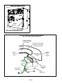
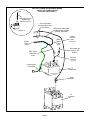
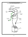
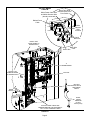
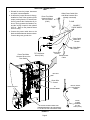
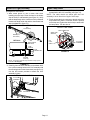
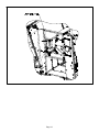
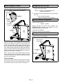
The Lennox C1UVCL10A-2 is a germicidal light kit designed to reduce microbial life forms (viruses, bacteria, yeasts, and molds) in the air. It uses ultraviolet (UVC) energy to effectively combat mold growth and proliferation on illuminated surfaces. The enhanced rapid start ballast provides UVC lamp operation at a full range of operating conditions, indicated by LED status lights. The kit includes a door switch that de-energizes the UVC light when the door is opened, ensuring safety.
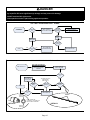
The Lennox C1UVCL10A-2 is a germicidal light kit designed to reduce microbial life forms (viruses, bacteria, yeasts, and molds) in the air. It uses ultraviolet (UVC) energy to effectively combat mold growth and proliferation on illuminated surfaces. The enhanced rapid start ballast provides UVC lamp operation at a full range of operating conditions, indicated by LED status lights. The kit includes a door switch that de-energizes the UVC light when the door is opened, ensuring safety.


-
 1
1
-
 2
2
-
 3
3
-
 4
4
-
 5
5
-
 6
6
-
 7
7
-
 8
8
-
 9
9
-
 10
10
-
 11
11
-
 12
12
-
 13
13
-
 14
14
-
 15
15


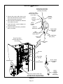
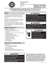
The Lennox C1UVCL10A-2 is a germicidal light kit designed to reduce microbial life forms (viruses, bacteria, yeasts, and molds) in the air. It uses ultraviolet (UVC) energy to effectively combat mold growth and proliferation on illuminated surfaces. The enhanced rapid start ballast provides UVC lamp operation at a full range of operating conditions, indicated by LED status lights. The kit includes a door switch that de-energizes the UVC light when the door is opened, ensuring safety.
Ask a question and I''ll find the answer in the document
Finding information in a document is now easier with AI
Related papers
-
Lennox D-Box User manual
-
-
-
-
-
Lennox Rooftop Unit Operating instructions
-
-
Lennox SSB User manual
Other documents
-
 Healthy Climate UV-2000 Homeowners Manual & Dealer Installation Instructions
-
FIELD CONTROLS FlexMountUV UV-13FM and UV-17FM Air Purifier Installation guide
-
-
Bard 46441700 User manual
-
-
Reznor SDH Installation guide
-
-
CFM CX3000GS User manual
-
Healthcare Lighting 2403413 User manual
-
Atari gvrSX User manual
