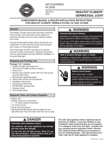
Reznor SDH Installation guide

Type
Installation guide

This manual is also suitable for

Reznor SDH is a versatile cooling system with an optional germicidal UV light (Option UV2) for enhanced air purification. Ideal for commercial and industrial settings, its cooling module efficiently maintains comfortable indoor temperatures. The UV2 light, when installed, actively combats harmful microorganisms, promoting a cleaner and healthier environment.

Reznor SDH is a versatile cooling system with an optional germicidal UV light (Option UV2) for enhanced air purification. Ideal for commercial and industrial settings, its cooling module efficiently maintains comfortable indoor temperatures. The UV2 light, when installed, actively combats harmful microorganisms, promoting a cleaner and healthier environment.

Form I-PREEVA-UV, P/N 220705, Page 1
Installation Form for
Cooling Coil UV Light, Option UV2
Form I-PREEVA-UV
Description and
Application
Option UV2, germicidal ultra-violet light, is designed for installation in Reznor
PREEVA Models PDH, SDH, and RDH with an optional cooling module that has
either a DX or a chilled water coil. The light is installed in the blower section down-
stream from and facing the cooling coil. Option UV2 light requires a separate dedi-
cated power source which may be 115V/1Ph, 208V/1Ph, or 230V/1Ph.
Read this entire instruction manual before beginning installation. Comply with all
warnings and safety considerations.
Reznor, LLC cannot and does not guarantee that all organisms will be inactivated
or killed or that use of Option UV2 light will prevent infection or illness. Additionally,
the health aspects associated with the use of this product and its ability to aid in
disinfection of environment air have not been investigated by UL.
Safety
Considerations
Installation and servicing of air conditioning equipment can be hazardous due to
system pressure and electrical components. Only trained and qualied service
personnel should install, repair, or service air conditioning equipment.
Follow all safety codes. Wear safety glasses and work gloves and cover all exposed
skin when installing or servicing ultra-violet light.
HAZARD INTENSITY LEVELS
DANGER: Failure to comply will result in severe personal injury or
death and/or property damage.
WARNING: Failure to comply could result in severe personal injury
or death and/or property damage.
CAUTION: Failure to comply could result in minor personal injury
and/or property damage.
Denitions
of Cautions,
Warnings, and
Dangers
WARNING
Improper installation, adjustment, alter-
ation, service, or maintenance can
cause property damage, personal injury,
or death. A qualied installer or service
agency must perform installation and
service.
CAUTION
Use only the specied high-output, low
temperature bulbs with this lamp. Use
of a lower wattage or incorrect bulb can
result in damage to the light and/or the
bulb. (See replacement list on page 4.)
WARNING
Before installing or servicing an
Option UV2 light, turn off the main
power switch to both the light xture
and to the unit. Electrical shock can
cause injury or death.
CAUTION
Never expose eyes or skin to ultra-
violet light from any source. Light
must be off before opening the door
on the blower section, cooling coil
module, optional mixing box, and
optional evaporator cooling module.
Never use the UV lamp for lighting.
Applies to: Models PDH, SDH, RDH with Cooling Module
Page 2
CAUTION
Do not touch bulb glass without gloves.
Oil from ngerprints will permanently
etch glass of bulb and weaken structure.
Clean bulb after handling.
CAUTION
Bulb contains a small amount of
mercury. If a bulb breaks, clean with
care and dispose of using an envi-
ronmentally safe disposal method.
The Option UV2 light is factory-installed in the blower section, downstream of the
cooling coil. PREEVA Sizes 75-150 have one light xture; Sizes 175-400 have
two. The bulb(s) are shipped in the blower section attached to each xture but not
installed for use. When handling a bulb, wear gloves and DO NOT TOUCH the
glass; handle only on the ends.
In units with a DX coil, there will also be a parts bag containing three hole plugs.
Field-supplied components include a disconnect switch, 14 gauge wiring, metal
conduit or aluminum tape, and conduit connection or wire bushing.
Installation
Instructions
1. Turn off all power to the unit. Open the blower and electrical compartment
doors.
2. Ultra-violet light may damage certain plastics and exposed non-UVC protected
wires. Any eld-supplied wiring or plastics in the blower compartment must be
wrapped with aluminum tape or installed in metal conduit.
Field
Connection
Panel
NOTE: The field connection panel is shown above with a unit on/off switch and a convenience outlet.
Both are optional and may not be on the unit being installed.
Mark and
drill hole(s)
for attaching
disconnect
switch.
Cooling Coil
Module
Blower
Section
Heat
Section
Electrical
Compartment
Airflow
FIGURE 1 -
Location and
Installation of
Field-Supplied
Disconnect Switch
Install disconnect switch wiring. Refer to the wiring diagram
in FIGURE 2. Wiring must be 14 gauge. Run wires from the
disconnect switch location through the factory-supplied con-
duit at the electrical compartment wall to the blower door
interlock switch junction box.
Example of one type of
eld-installed UV light
disconnect switch
Factory-installed blower
door safety interlock switch
Safety Considerations (cont’d)
3. A separate, dedicated power
supply must be used for the
Option UV2 light. Do not use unit
wiring or control box connec-
tions.
Wiring must comply with national
and local codes. Power source
must be a suitable fused,
grounded, protected source with
the correct voltage. Voltages other than
115/1, 208/1, 230/1 will permanently
damage the lamp. Wire per TABLE 1.
TABLE 1 - Supply Wiring
Wiring Wire Color
Power Black
Neutral White
Ground Green
4. Install the eld-supplied disconnect switch. See FIGURE 1 and follow
instructions.
a) Locate the eld connection panel. Mark and drill hole(s) for attaching eld-
supplied disconnect switch .
Location and
Components
Form I-PREEVA-UV, P/N 220705, Page 3
5. Install the ultra-violet bulb(s).
CAUTIONS
Do not touch bulb glass without gloves. Oil from
ngerprints will permanently etch the glass and
weaken bulb structure. Clean bulb after handling.
Install the bulb BEFORE the power is applied.
Installing the bulb while power is on will trigger
the “end-of-lamp-life circuit”, and the bulb will
not light. If this happens, shut off power, wait ten
minutes, and turn power on. Bulb should light.
The bulb is shipped in its original carton which is cable tied to the
installed light xture. See FIGURE 3. Grasping only the ends of
the bulb (not the glass), remove it from the package.
Using a lint free cloth and isopropyl alcohol, clean the bulb. Fin-
gerprints on a bulb will permanently damage it. Push the bulb
into place until it is seated. Rotate 90° until two distinct clicks
are heard.
FIGURE 3 - Bulb Shipping
Location in Blower Section
Bulbs)
are shipped
in their original car-
ton and require eld
installation. Read
cautions before
removing
bulb.
b) Refer to the wiring diagram in FIGURE 2 and run eld-supplied 14 gauge
wiring from the disconnect switch location, through the factory-installed con-
duit, to the junction box for the blower door interlock switch.
c) Install the disconnect switch and connect the wires.
If a connection opening
is not used, remove
that grommet and
replace it with
a hole plug.
FIGURE 4 -
Coil Cabinet
Module with
DX Coil
6. DX Coil Only - Plug all unused openings.
If the unit has a DX coil, all openings in the cooling
coil module for line connections must be used or
plugged. If any openings are unused, remove the
factory-installed grommet and replace it with the
appropriate size hole plug provided in the plastic
parts bag. See FIGURE 4.
7. Test bulb. Wear safety glasses and cover skin.
Standing as far away as possible, turn power on to
the light and depress door interlock switch. If bulb
glows with a blue hue, turn off power. If bulb does
not glow, turn off the power and nd the cause.
BLOWER DOOR
INTERLOCK SWITCH
Models 175-400 only
Lamp Ballast #2
Lamp
Ballast #1
- Applies to
All Sizes
2 x 4 JUNCTION BOX
FIELD SUPPLIED
FUSED DISCONNECT
LINE/1/60
Field Connection
Panel
OPTION UV2 WIRING
(UVC Lights are located in
the blower compartment.)
#14 Ga
White
#14 Ga
Black
#14 Ga White
#14 Ga
Green
#14 Ga Black
#14 Ga
White
#14 Ga
Black
GRD
#14 Ga
Green
GRD
GRD
Field wiring
Factory wiring
#14 Ga
Black
#14 Ga
Green
#14 Ga
Green
#14 Ga
Green
#14 Ga White
#14 Ga
Black
#14 Ga
Green
#14 Ga Green
FIGURE 2 -
Wiring
Page 4
Operation
Ultra-violet lamp should be operated continuously from its power source. Lamp
should not be connected to indoor fan power source or any power source where
lamps would be cycled more than twice a day.
While lit, the bulb color should be light blue. If bulb color changes to red or ickers,
replace the bulb. Bulbs that are not light blue will not emit ultra-violet radiation and
will not kill harmful bacterial or fungi.
Fiberglass lter media is recommended for lters exposed to ultra-violet light. Poly-
ester or cotton lters are subject to ultra-violet degradation and are not recom-
mended.
Maintenance
and Service
Disconnect all power before performing any maintenance or service.
Bulbs need periodic replacement to maintain design specications. Replace bulbs
after 6000 hours of operation or one year, whichever comes rst. For best perfor-
mance, replace bulbs at the beginning of each cooling season.
Output can also be checked with a UVC radiometer. Replace bulb when output
falls to 70% of initial reading.
CAUTION
Use only specied high output, low temperature bulbs with
this xture. Use of a lower wattage or incorrect bulb can result
in damage to xture or bulb.
See table below for replacement bulb P/N’s. Other bulbs may plug into the xture
but they should not be used. Non-approved bulbs will overheat bulb and power
source. Normal operating temperature for the bulb is 80°F; normal operating tem-
perature for the power source is 125°F.
Replacement Parts
Description 75/100 125/150 175/200/225 250/300/350/400
UVC Bulb, Steril-Aire
#GTD VO
220440 220441 (2) 220440 (2) 220442
22” (559mm) 34” (864mm) 22” (559mm) 40” (1016mm)
Light Fixture, 115/208/
230V, Steril-Aire #DE-
220434 220435 (2) 220434 (2) 220436
241VO 361VO 241VO 421VO
Blower Door Interlock Safety Switch - All Sizes, P/N 217262
Troubleshooting
Symptom Recommended Action (in order of priority)
Bulb does not
light.
1. Turn off power. Wait 10 minutes and turn power on.
2. Replace bulb (see P/N’s above). Recommend bulb(s) be replaced at the
beginning of every cooling season.
3. Check line voltage.
4. Check wiring to the bulb.
5. Replace power supply.
Low output radi-
ometer reading or
visibly weak light.
1. Replace bulb (see P/N’s above).
2. Check line voltage.
3. Checking wiring to bulb.
Red/orange light. 1. Check ambient temperature. If the temperature is at or below 35°F, bulb
is too cold to operate properly.
2. If ambient temperature is above 35°F, see “low output” above.
(800) 695-1901, www.ReznorHVAC.com
©2014 Reznor,LLC. All rights reserved.
Trademark Note: Reznor
®
and PREEVA
®
are registered in at least the United States.
0514 Form I-PREEVA-UV (Version 0.1)
Check the wiring and the switches or replace the bulb. Retest and check until
light operates properly.
8. Close the doors and turn on power to the unit.
Instructions
(cont’d)

  • Page 1 1
  • Page 2 2
  • Page 3 3
  • Page 4 4

Reznor SDH Installation guide

Type
Installation guide
This manual is also suitable for

Reznor SDH is a versatile cooling system with an optional germicidal UV light (Option UV2) for enhanced air purification. Ideal for commercial and industrial settings, its cooling module efficiently maintains comfortable indoor temperatures. The UV2 light, when installed, actively combats harmful microorganisms, promoting a cleaner and healthier environment.

Ask a question and I''ll find the answer in the document

Finding information in a document is now easier with AI