Aprilaire 8140 Owner's manual

Type
Owner's manual

This manual is also suitable for

MODEL 8140 FRESH AIR VENTILATOR MODEL 8140NC FRESH AIR VENTILATOR
SAFETY INSTRUCTIONS
WARNING
1. 120 Volts may cause serious injury from electric shock. Disconnect electrical power before starting installation or servicing. Leave power
disconnected until installation/service is completed.
2. Sharp edges may cause serious injury from cuts. Use care when cutting plenum openings and handling duct work.
CAUTION
1. Read all instructions before beginning installation.
2. Improper installation may cause property damage or injury. Installation, service, and maintenance must be performed by a qualified service
technician.
READ AND SAVE THESE INSTRUCTIONS
VENTILATION CONTROLLER
FILTER
COVER
VENTILATION TERMINALSLOW PRESSURE PORTHIGH PRESSURE PORT
INLET COLLAR AND
NORMALLY CLOSED
POWER DAMPER
OUTLET
COLLAR
WALL MOUNT
BRACKET LOCATION
JOIST MOUNT
BRACKET LOCATION
TABLE OF CONTENTS
Safety Instructions ...............................................1
Introduction and Compliance Statement ...........................2
Specifications ...................................................2
Install Electrical Outlet............................................2
Ventilator Location and Orientation................................3
Mount the Ventilator .............................................3
Mount Intake Hood ..............................................4
Install Ductwork .................................................4
Model 8140NC – Wiring to Various Controls ........................5
Model 8140NC – Test Mode .......................................6
Model 8140NC – Sequence of Operation ...........................6
Model 8140 – Wiring the Control to the HVAC System ...............6
Model 8140 – Connecting the Control to the Ventilator ..............7
Model 8140 – Operation ..........................................7
Model 8140 – Test Mode..........................................8
Measure Delivered Airflow ........................................8
Model 8140 – Set Up . . . . . . . . . . . . . . . . . . . . . . . . . . . . . . . . . . . . . . . . . . . . .9
Model 8140 – Rater/Inspector Verification .........................10
Model 8140 – Sequence of Operation .............................10
Filter Cleaning...................................................11
Internal Schematics ..............................................11
Limited Warranty ...............................................12
Model 8140 and 8140NC
Fresh Air Ventilator
Installation and Operating Instructions
10012996 B2208006B 7.19
English 1
INTRODUCTION AND COMPLIANCE STATEMENT
The Model 8140 and 8140NC Fresh Air Ventilators are designed to bring in precisely the right amount of outdoor air into today’s efficiently designed
homes. Duct the inlet of the ventilator to an outdoor air intake and duct the discharge to the HVAC system, then simply plug the unit in, set the
amount of needed ventilation and select the desired temperature limits.
Temperature limits are set on the control to avoid bringing in outdoor air during the hottest or coldest period of the day. The built in control will
automatically compensate for the ventilation time that is missed by bringing in additional outdoor air during milder periods of the day. Compliance
with the requirements of ASHRAE 62.2-2010 is met as the control adds ventilation time as needed to account for the fractional on-time and
effectiveness of the ventilation schedule. The control will also ensure that ventilation occurs no less than one hour of every four. When properly
installed and set, the Model 8140 and 8140NC Fresh Air Ventilators will meet the mechanical ventilation requirements of:
Energy Star Certified Homes, Version 3
EPA Indoor airPLUS, Version 1
2012 & 2015 International Residential Code (IRC)
2012 & 2015 International Energy Conservation Code (IECC)
California Energy Commission Title 24
SPECIFICATIONS
TABLE 1 – SPECIFICATIONS
External Static Pressure ("w.c.) Airflow (CFM) Efficacy (CFM/watt) Voltage
0.0 250 4.5
120 VAC
1 phase
60 Hz
0.2 205 3.8
0.4 165 3.1
0.6 125 2.1
17.15
14.00
22.13
27.75
11.60
10.50
14.31
INLET: ROUND COLLAR
FOR 6" DIAMETER DUCT
OUTLET: OVAL COLLAR
FOR 6" DIAMETER DUCT
CONTROL NOT INCLUDED
ON MODEL 8140NC
90-2299
FIGURE 1 – DIMENSIONS (INCHES)
INSTALL ELECTRICAL OUTLET
Install a standard NEMA 5-15 receptacle suitable for the location, near where the ventilator will be installed. The ventilator comes equipped with a
6-foot power cord with a standard 3-prong plug.
2 English
MOUNTING BRACKET LOCATIONS
MOUNTED TO THE JOIST HUNG FROM THE JOIST
AIR FLOW
MOUNTED TO WALL OR FLOOR JOISTS
90-2241
FIGURE 3 – MOUNTING BRACKET POSITIONING
VENTILATOR LOCATION AND ORIENTATION
CAUTION
1. Mount the blower with the lowest, exposed moving parts at
least 8 feet (2.4 m) above floor or grade level.
2. Mount the blower at least 3.3 feet (1.0 m) from any accessible
opening of the duct.
Choose a location for the ventilator that is within 6 feet of the outlet
into which the ventilator will be plugged. Allow space for filter removal
and service as shown in FIGURE 2.
The ventilator can be mounted in any orientation.
10"
FILTER
ACCESS
24"
MOTOR
ACCESS
90-2241
FIGURE 2 – CLEARANCES FOR SERVICING
MOUNT THE VENTILATOR
1. Install the mounting brackets, using the supplied #8 x 1/2" screws, to the side of the housing as shown in FIGURE 3. Use the holes nearest the
covers for mounting to floor joists or hanging from rafters. Use the holes near the bottom of the unit for mounting to a flat wall or ceiling surface.
2. Secure the ventilator into joists or a strong platform and screw into place using the #10 x 3/4" screws provided. The ventilator weighs
approximately 25 pounds, so do not secure it into drywall alone.
English 3
MOUNT INTAKE HOOD
Install a weather tight hood with a bird screen.
Cut a hole in the exterior wall that is large enough to fit 6" insulated flexible duct through with minimal compression of the insulation. Pull the duct
through the hole and attach the flex duct to the collar of the hood. Use metal foil tape or a plastic zip-tie to secure the duct to the collar. Pull the
insulation and vapor barrier over the duct and tape it to the collar.
IMPORTANT: The end of the insulation must be sealed to prevent condensation from forming inside the insulation. If a plastic zip-tie is used to
secure the insulation to the hood collar, also tape the end to seal it against condensation problems.
Press the hood against the outside wall and secure in place with screws; seal around the perimeter of the hood with caulk.
INSTALL DUCTWORK
Install 6" diameter flexible, insulated duct
from the round inlet collar of the unit to the
intake hood and from the oval outlet collar
of the unit to the HVAC system. Duct the
outlet of the ventilator to the return side of
the HVAC system (refer to FIGURE 4).
IMPORTANT: The end of the
insulation must be sealed to prevent
condensation from forming inside
the insulation. If a plastic zip-tie is
used to secure the insulation to the
hood collar, also tape the end to seal
it against condensation problems.
FILTER
FURNACE/AIR HANDLER
AIR FLOW
FRESH AIR
VENTILATOR
FRESH AIR INTAKE DUCT
FRESH AIR
OUTSIDE
WALL
TYPICAL BASEMENT INSTALLATION
FRESH AIR
VENTILATOR
GABLE END WALL, BAND JOIST, OR PORCH SOFFIT
FRESH AIR
FRESH AIR INTAKE DUCT
FRESH AIR
INTAKE HOOD
WITH SCREEN
FRESH AIR
INTAKE HOOD
WITH SCREEN
RETURN MIXING BOX
FURNACE/AIR
HANDLER
FILTER
AIR FLOW
TYPICAL ATTIC INSTALLATION
90-2241
FIGURE 4 – DUCTING IN UPFLOW AND HORIZONTAL HVAC SYSTEMS
4 English
MODEL 8140NC – WIRING TO VARIOUS CONTROLS
Suggested Controls:
Aprilaire IAQ Control Models 8910, 8910W or 8920W
Aprilaire Thermostat Models 8620 or 8620W
Model 8120A or 8120X Digital Ventilation Controller
Select the diagram that corresponds to the control to be used. Wire the controls to the HVAC equipment and any other IAQ accessory in accordance
with the literature provided with the control.
CONTROL MODULE OF IAQ CONTROL
VENT
SEE
NOTE 1
MODEL 8120A DIGITAL VENTILATION CONTROLLER
VENT
OUTPUTSINPUTSPOWER
GW
CR VENTO DT GfUSED
N OT
SEE NOTE 1
MODEL 8620/8620W THERMOSTAT
VENT
C I2
I1 Y
O/B RC
RG
Y2 W2
L T2
T1
S1
S2
W
R
C
Y
W
O
Gs
Gh
ODT
VENT
MODEL 8120X DIGITAL VENTILATION CONTROLLER
VENT
SEE NOTE 1
FIGURE 5 – WIRING TO IAQ CONTROL
FIGURE 7 – WIRING TO MODEL 8120A
FIGURE 6 – WIRING TO THERMOSTAT
FIGURE 8 – WIRING TO MODEL 8120X
NOTE 1: An outdoor temperature sensor must be installed to use outdoor temperature limits for ventilation control.
English 5
MODEL 8140NC – TEST MODE
After all ducting and wiring is complete, plug in the ventilator, restore power to the HVAC system and make sure the switch controlling the outlet into
which the ventilator is plugged (if applicable) is turned on.
1. Use the installed control to complete a circuit between the VENT terminals on the 8140NC.
2. Verify that the ventilator blower starts and that the integral damper opens.
3. If the ventilator has been wired to turn on the HVAC blower with ventilation, verify that the blower is on.
4. Measure the airflow (CFM) that the installed ventilator is delivering. See MEASURE DELIVERED AIRFLOW section on page 8.
5. Using the instructions provided with the installed control, adjust the ventilation settings as required.
MODEL 8140NC – SEQUENCE OF OPERATION
Refer to the installation manual provided with the control that is wired to the Model 8140NC.
MODEL 8140 – WIRING THE CONTROL TO THE HVAC SYSTEM
NOTICE
Disconnect power to HVAC system during wiring to avoid
electrical shorts.
1. Remove the control from the mounting plate as shown in FIGURE 9.
Set control aside in a safe place until all wiring has been completed.
2. Run a 6-conductor (min.) cable (for furnace/AC applications) or a
7-conductor (min.) cable between the control and the HVAC system.
3. Wire to the HVAC system in accordance with FIGURE 10 if installed in
a furnace/AC application or FIGURE 11 if installed with a heat pump.
CONTROL CONNECTOR
CONTROL
MOUNTING
PLATE
CONTROL
VENTILATION CONTROL
R
C
Y
W
G
R
C
Y
W
G
THERMOSTAT
WIRE NUT
(FIELD
SUPPLIED)
R
C
Y
W
O
GS
GH
FURNACE
R & C = 24 VAC
Y = COOLING
W = HEAT
GS = FAN INPUT
GH = FAN OUTPUT
VENT
O DT
90-2299
FIGURE 9 – REMOVE CONTROL FROM MOUNTING PLATE
FIGURE 10 – WIRING VENTILATION CONTROL TO A FURNACE
6 English
VENTILATION CONTROL
R
C
Y
W1
G
R
C
Y
W
G
HEAT PUMP THERMOSTAT
WIRE NUT
(FIELD
SUPPLIED)
O
R & C = 24 VAC
Y = COMPRESSOR
W1 = 1st STAGE AUX. HEAT
O = REV. VALVE, COOLING
GS = FAN INPUT
GH = FAN OUTPUT
R
C
Y
W
O
GS
GH
VENT
O DT
HEAT PUMP
O
FIGURE 11 – WIRING VENTILATION CONTROL TO A HEAT PUMP
MODEL 8140 – CONNECTING THE CONTROL TO THE VENTILATOR
Plug the Control Connector into the back of the
control at the location shown in FIGURE 12. Route
the connector wire through the channels in the
control and reattach the control to the mounting
plate. Restore power to the HVAC system and plug
in the ventilator when complete.
CONTROL BACK CONTROL FRONTCONTROL MOUNTING PLATE
90-2291
FIGURE 12 – PLUG THE CONTROL INTO THE VENTILATOR
MODEL 8140 – OPERATION
The display will appear faint normally; the first press of any button will turn on the display at full power.
MIN/
HR
CODE
Use for Rater/Inspector Verification.
Press and hold for 5 seconds to
enter Test Mode or Set Up Menu.
Lights green when ventilating.
Shows the ventilation time setting (minutes/hr), mode of operation
(Code or Comfort) and whether the HVAC fan has been turned on when ventilating.
Use to override the calculated ventilation
time setting (6 – 60 minutes/hr). Press
and hold to turn ventilation OFF.
To return to the calculated setting, go
completely through the Set Up Menu.
English 7
MODEL 8140 – TEST MODE
After wiring and set up have been completed, Test Mode can be used to verify that all components in the ventilation system function and that wiring
to the HVAC system fan is correct.
2
3
TABLE 2 – MODEL 8140 TEST MODE MENU
Test Sequence Description
HP
°F
HC
%
Shows outdoor temperature or ----°F if no
separate outdoor temperature sensor has been
installed. Model 8140 installations do not require a
separate sensor – outdoor temperature is measured
by the control's on-board sensor.
tESt shows on the display, the green Fresh Air LED
will light and either the damper will open or the
power ventilator will turn on depending on what
has been wired to the VENT terminals.
1
Hold for 5 seconds.
MEASURE DELIVERED AIRFLOW
1. Make sure the ventilator is plugged in and wired to an external control (Model 8140NC) or that
the integral control is wired to the HVAC system (Model 8140).
2. Use 1/4" flexible tubing to attach a pressure gauge set to " w.c. (sometimes shown as “in. w.g.
or “in. H2O”) to the inlet and outlet pressure ports on the ventilator. The pressure gauge should
have as small a range as possible to get a meaningful measurement – a range of 1.0" w.c. should
be sufficient. Connect the high or “+” port of the gauge to the outlet pressure port on the
ventilator, and the low or “-“ port of the gauge to the inlet pressure port on the ventilator. See
FIGURE 13.
3. Model 8140NC – Turn on the ventilator using the installed control for the Model 8140NC. This
can be done by temporarily changing the ventilation setting to 60 minutes/hour or you can
simply place a jumper between the VENT terminals of the ventilator.
Model 8140 – Turn on the ventilator by using the “Up” button to increase the ventilation setting
to 60 MIN./HR.
4. Use the label on the cover of the ventilator, or TABLE 3, to convert the pressure reading to
delivered airflow. If the pressure reading false between listed values, either use the lower value
or interpolate between values: CFM = Lower Value + [(Higher Value – Lower Value) * 10 *
(Pressure Reading – Lower Value Pressure)]. The following is an example:
a. Measured Pressure Reading is 0.34" w.c.
b. Table 2 lists 205 CFM @ 0.3" w.c. and 175 @ 0.4" w.c.
c. Either use 175 CFM or interpolate:
CFM = 175 + [(205-175) * 10 * (0.34-0.3)] = 175 + [(30) * 10 * (.04)] = 175 + 12 = 187 CFM
Interpolating will demonstrate higher delivered airflow, but requires a calculation to be done.
TABLE 3 – DELIVERED AIRFLOW
CORRESPONDING TO MEASURED PRESSURE
AT VENTILATOR PRESSURE PORTS
Measured Pressure
(" w.c.)
Delivered Airflow
(CFM)
0.1 250
0.2 230
0.3 205
0.4 175
0.5 145
0.6 110
0.7 70
TABLE 2 – MODEL 8140 TEST MODE MENU
Test Sequence Description
MEASURED REQ’D CONT CFM
FAN
After 15 seconds, the HVAC fan will turn on if it has
been wired and set up to do so. The display will
show FAN along with tESt.
MIN/
HR
CODE
After 45 seconds Test Mode automatically
completes and the display returns to the operating
display.
INLET
OUTLET
Lo
Hi
-
+
90-2354
FIGURE 13 – MEASURE PRESSURE AT
INLET AND OUTLET PRESSURE PORTS
8 English
MODEL 8140 – SET UP
NOTICE
Before setting up the control for use, the amount of ventilation air being delivered (CFM) by the installed ventilation system must be measured.
1
Hold for 5 seconds, then release.
2
Throughout the Set Up Menu, the and buttons are used to change values, the Select button is used enter the value and move on to the next Set
Up Menu item.
TABLE 4 – MODEL 8140 SET UP MENU
Menu Item Values
Description
HP
HC
HP or HC
HP if wiring to a heat pump.
HC if wiring to furnace and AC.
CODE
#
BEDROOMS
HIGH
1 – 10
Number of bedrooms
used to calculate required
continuous ventilation rate.
COMFORT
HOUSE
(
FT
2
)
LOW
500 – 7500 ft2
Square footage – used to
calculate required continuous
ventilation rate.
MEAS
REQ
D CONT
CFM
FAN
30 – 250 CFM
Measured outdoor airflow
delivered during ventilation.
HP
°F
CODE NO.OF BEDROOMS
HIGH
OFF,
85°F – 105°F
Ventilation high temperature
limit. Ventilation is limited
when the outdoor temperature
exceeds the setting. Turn OFF if
no high limit is desired.
HP
°F
COMFORT HOUSE (FT
2
)
LOW
OFF,
-10°F – 40°F
Ventilation low temperature
limit. Ventilation is limited
when the outdoor temperature
falls below the setting. Turn
OFF if no low limit is desired.
MEAS REQ’D CONT CFM
FAN
On, “bLnd”, OFF
ON HVAC fan turns on
whenever ventilation occurs.
bLnd (blend) HVAC fan turns
on with ventilation only when
the outdoor temperature is
outside a set range.
OFF HVAC fan is not turned on
with ventilation.
TABLE 4 – MODEL 8140 SET UP MENU
Menu Item Values
Description
HP
°F
MEAS REQ’D CONT CFM
FAN
CODE # BEDROOMS
HIGH
OFF, 60°F to 5°F
less than Vent.
High Temp. Limit
Only available when bLnd is
selected. When the outdoor
temperature is above the
setting, the HVAC fan will
be turned on to mix (blend)
outdoor air with indoor air for
tempering.
HP
°F
MEAS REQ’D CONT CFM
FAN
COMFORT HOUSE (FT
2
)
LOW
OFF, 5°F less
than Vent. Low
Temp. Limit to
55°F
Only available when bLnd is
selected. When the outdoor
temperature is below the
setting, the HVAC fan will
be turned on to mix (blend)
outdoor air with indoor air for
tempering.
CODE
COMFORT
See IMPORTANT
NOTE below.
“codE”, “cFrt”
codE No RH limits and any
missed ventilation due to
temperature is made up per
ASHRAE 62.2-2010.
cFrt (comfort) Adds indoor RH
limits to ventilation; ventilation
missed due to limits is not
made up.
HC
%
CODE # BEDROOMS
HIGH
OFF,
45% – 70% RH
Only available when cFrt is
selected. When the outdoor RH
exceeds the setting, ventilation
will not occur.
HC
%
COMFORT HOUSE (FT
2
)
LOW
OFF,
10% – 30% RH
Only available when cFrt is
selected. When the outdoor
RH drops below the setting,
ventilation will not occur.
When all Set Up Menu options have been entered, the control will
display donE.
IMPORTANT NOTE: The 8140 control senses the temperature and humidity of the outdoor air. To prevent extended periods of inactivity, set the
control mode to codE, or if setting to cFrt (comfort), set the RH limits to OFF.
English 9
MODEL 8140 – RATER/INSPECTOR VERIFICATION
To verify the ventilation time setting, press the Select button to scroll through the calculated Required Continuous CFM and the Measured CFM for
this installation. If any value does not match the expected value, the Set Up Menu must be entered to change the floor area, number of bedrooms or
measured CFM.
The calculation used for the ventilation time setting is (all calculations compliant with ASHRAE Standard 62.2-2010):
)
Required Continuous CFM
Measured CFM
(
Minutes per Hour = 60
*
Required Continuous CFM =
(
(Floor Area ft
2
*
.01) + (No. of Bedrooms + 1)
*
7.5
)
Measured CFM is entered during set up and Required Continuous CFM is calculated according to the equation below:
MIN/
HR
CODE
MEAS
REQ
D CONT CFM
FAN
MEAS
REQ
D CONT
CFM
FAN
MODEL 8140 – SEQUENCE OF OPERATION
“CODE” SETTING
The control will turn on ventilation with a heating, cooling or fan call for the set number of minutes during a one-hour cycle period. If the outdoor
temperature is above the high temperature ventilation limit, ventilation will not occur with a cool or fan call, but if it is below the low temperature
ventilation limit it will occur with a heat call. If the HVAC equipment does not turn on enough to meet the ventilation time within the hour, the control
will turn on ventilation without a call, if the outdoor air temperature is within the high and low ventilation temperature limits. The control will also
turn on the HVAC system blower, if wired and set up to do so.
If the outdoor temperature exceeds the limits set at the end of the first hour, then no additional ventilation will occur for another 60 minutes, and the
cycle period will automatically adjust to four hours. When the ventilator starts again, it will sample the air temperature and if in range, will meet the
set amount of ventilation during the four-hour cycle period. For example, if the Vent Time was set to 25 minutes per hour and the air temperature fell
below the low limit setting ventilation would only occur during a heating call. If the heating only operated for 10 minutes during the hour, the control
will automatically change the cycle period to four hours and work to provide the additional 90 total minutes of ventilation (25 min/hr * 4 hours = 100
minutes, minus the 10 minutes of ventilation that occurred during heating) during the four-hour cycle period.
If the air temperature is still out of range, the control will automatically switch to an 8-hour cycle period, then a 12-hour cycle period and finally a
24-hour cycle period. During 8, 12 and 24 hour cycle periods, the total ventilation time increases to compensate for ventilation effectiveness as defined
in ASHRAE Standard 62.2-2010. When the cycle period automatically adjusts to 24-hours, the control will turn on ventilation to meet the requirements
even if the temperature is outside of the set limits.
“COMFORT” SETTING
The control will turn on ventilation with a heating, cooling or fan call by the HVAC equipment, if the outdoor air temperature is within the high and
low ventilation temperature limits and the outdoor RH is within the high and low RH limits, for the set number of minutes during a one-hour cycle
period. If the HVAC equipment does not turn on enough to meet the ventilation time within the hour, the control will turn on ventilation without a
call, if the outdoor air temperature and indoor RH is within the set limits. The control will also turn on the HVAC system blower, if wired and set up to
do so.
10 English
FILTER CLEANING
Normally, the fresh air filter will need to be removed and cleaned every six months, but check it after the first three months following installation to
determine if more or less frequent cleaning will be necessary. After cleaning the filter inside the ventilator, clean off the screen at the fresh air intake
hood on the outside of the house. The most common cause of reduced ventilation is a clogged air intake hood.
To clean the ventilator filter:
1. Remove the two screws securing the filter door to the housing and swing open the door (FIGURE 14).
2. Rotate the plastic filter retainer to release the filter and remove it from the ventilator (FIGURE 15).
3. Use water to rinse the filter and shake the excess moisture off the filter.
4. Replace the filter in the ventilator, turn the filter retainer to secure it in the housing, and close and secure the filter door.
REMOVE (2) SCREWS
FILTER DOOR
PLASTIC
FILTER RETAINER
FIGURE 14 FIGURE 15
90-2241 90-2241
INTERNAL SCHEMATICS
RED
GRN
BLU
BRN
GRN
L2-WHT
L1-BLK
BLK
WHT
YLW
YLW
ORG
N
L
120 VAC
CON3
CON2
CON3
ORG
R
C
Y
W
O
Gs
Gh
VENT
O DT
WHT
RED
BLU
CAPPED RED & WHITE WIRES ARE LOCATED INSIDE THE FILTER DOOR TO POWER
THE CONTROL (R & C TERMINALS) FROM THE POWER PCB ASSEMBLY. USE ONLY
IF THE VENTILATON CONTROLLER WILL NOT BE WIRED TO THE HVAC SYSTEM.
M
M
BLOWER
RUN CAPACITOR
CHASSIS GROUND
GND
CHASSIS
GROUND
DAMPER
MOTOR
POWER PCB ASSEMBLY
VENTILATION CONTROLLER
FIGURE 16 – MODEL 8140 INTERNAL SCHEMATIC
English 11
LIMITED WARRANTY
Your Research Products Corporation Aprilaire® Fresh Air Ventilator is expressly warranted for five (5) years from date of installation to be free from defects in materials or workmanship.
Research Products Corporation’s exclusive obligation under this warranty shall be to supply, without charge, a replacement for any component which is found to be defective within such
five (5) year period and which is returned not later than thirty (30) days after said five (5) year period by you to either your original supplier or to Research Products Corporation, Madison,
Wisconsin 53701, together with the model number and installation date of the ventilator.
THIS WARRANTY SHALL NOT OBLIGATE RESEARCH PRODUCTS CORPORATION FOR ANY LABOR COSTS AND SHALL NOT APPLY TO DEFECTS IN WORKMANSHIP OR MATERIALS
FURNISHED BY YOUR INSTALLER AS CONTRASTED TO DEFECTS IN THE VENTILATOR ITSELF.
IMPLIED WARRANTIES OF MERCHANTABILITY OR FITNESS FOR A PARTICULAR PURPOSE SHALL BE LIMITED IN DURATION TO THE AFORESAID FIVE YEAR PERIOD. RESEARCH PRODUCTS
CORPORATION’S LIABILITY FOR INCIDENTAL OR CONSEQUENTIAL DAMAGES, OTHER THAN DAMAGES FOR PERSONAL INJURIES, RESULTING FROM ANY BREACH OF THE AFORESAID
IMPLIED WARRANTIES OR THE ABOVE LIMITED WARRANTY IS EXPRESSLY EXCLUDED. THIS LIMITED WARRANTY IS VOID IF DEFECTS(S) RESULT FROM FAILURE TO HAVE THIS UNIT
INSTALLED BY A QUALIFIED HEATING AND AIR CONDITIONING CONTRACTOR. IF THE LIMITED WARRANTY IS VOID DUE TO FAILURE TO USE A QUALIFIED CONTRACTOR, ALL DISCLAIMERS
OF IMPLIED WARRANTIES SHALL BE EFFECTIVE UPON INSTALLATION.
Some states do not allow limitations on how long an implied warranty lasts or the exclusion or limitation of incidental or consequential damages so the above exclusion or limitations may
not apply to you.
This warranty gives you specific legal rights and you may also have other rights which vary from state to state.
WARRANTY REGISTRATION
Visit us online at www.aprilaire.com to register your Aprilaire product. If you do not have online access, please mail a postcard with your name, address, phone number, email address, product
purchased, model number, date of purchase, and dealer name and address to: Research Products Corporation, P.O. Box 1467, Madison, WI 53701.
Your warranty registration information will not be sold or shared outside of this company.
TERMINAL
BLOCK
M
RED
BLOWER
RUN CAPACITOR
GRN
BLU
BRN
GRN
L2-WHT
L1-BLK
CHASSIS GROUND
GND
CHASSIS
GROUND
BLK
WHT
M
YLW
YLW
ORG
DAMPER
MOTOR
N
L
120 VAC
CON3
CON2
BLU
CON3
ORG
POWER PCB ASSEMBLY
FIGURE 17 – MODEL 8140NC INTERNAL SCHEMATIC
AprilairePartners.com
P.O. Box 1467
Madison, WI 53701-1467
800.334.6011 F: 608.257.4357
Printed in USA
©2019 Aprilaire – Division of Research Products Corporation
12 English
VENTILADOR DE AIRE FRESCO MODELO 8140 VENTILADOR DE AIRE FRESCO MODELO 8140NC
INSTRUCCIONES DE SEGURIDAD
ADVERTENCIA
1. El voltaje de 120V puede provocar lesiones graves por descarga eléctrica. Antes de comenzar con el proceso de instalación o de mantenimiento, desconecte
el artefacto. Deje el artefacto desconectado hasta que se complete la instalación.
2. Los bordes filosos pueden causar lesiones graves por cortes. Se debe tener precaución al cortar las aberturas de la cámara y manipular los conductos.
PRECAUCIÓN
1. Lea las instrucciones antes de comenzar con la instalación.
2. Si se instala el artefacto de manera incorrecta puede causar daños a la propiedad o lesiones. Un técnico calificado debe realizar la instalación, el servicio y el
mantenimiento del artefacto.
LEA Y CONSERVE ESTAS INSTRUCCIONES
CONTROLADOR DEL
SISTEMA DE VENTILACIÓN
TAPA DEL
FILTRO
TERMINALES DEL SISTEMA DE VENTILACIÓNPUERTO DE BAJA PRESIÓNPUERTO DE ALTA PRESIÓN
ANILLO DE ENTRADA
Y REGULADOR DE
ENERGÍA NORMALMENTE
CERRADO
ANILLO
DE SALIDA
UBICACIÓN DEL
SOPORTE PARA PARED
UBICACIÓN DEL
SOPORTE PARA VIGA
ÍNDICE
Instrucciones de seguridad .............................................. 1
Introducción y declaración de cumplimiento...............................2
Especificaciones ........................................................2
Instalación del tomacorriente ............................................2
Ubicación y orientación del ventilador ....................................3
Instalación del ventilador ...............................................3
Instalación del extractor de admisión .....................................4
Instalación de los conductos .............................................4
Modelo 8140NC: cableado para varios controles............................5
Modelo 8140NC: modo de prueba ........................................6
Modelo 8140NC: secuencia de funcionamiento.............................6
Modelo 8140: cableado del control al sistema de HVAC .....................6
Modelo 8140: cómo conectar el control al ventilador........................7
Modelo 8140: funcionamiento ............................................7
Modelo 8140: modo de prueba ...........................................8
Medición del flujo de aire distribuido......................................8
Modelo 8140: configuración ..............................................9
Modelo 8140: verificación del evaluador/inspector.........................10
Modelo 8140: secuencia de funcionamiento...............................10
Limpieza del filtro.......................................................11
Esquemas internos......................................................11
Garantía limitada ......................................................12
Ventilador de aire fresco modelo 8140 y 8140NC
Instrucciones de instalación y funcionamiento
10012996 B2208006B 7.19
Español 1
INTRODUCCIÓN Y DECLARACIÓN DE CUMPLIMIENTO
El ventilador de aire fresco modelo 8140 y 8140NC está diseñado para incorporar de manera precisa la cantidad correcta de aire del exterior a las viviendas actuales
diseñadas eficientemente. Conduzca la entrada del ventilador a una entrada de aire exterior y conduzca la descarga al sistema de HVAC; luego, simplemente enchufe
la unidad, configure la cantidad de ventilación necesaria y seleccione los límites de temperatura deseados.
Los límites de temperatura se configuran en el sistema de control para evitar incorporar aire del exterior durante los períodos más calurosos del día. El sistema de
control integrado compensará de manera automática el tiempo de ventilación que se pierde al incorporar más aire del exterior durante los períodos más templados
del día. Se cumple con los requisitos de la norma 62.2-2010 de ASHRAE, ya que el sistema de control agrega tiempo de ventilación, si es necesario, según el
porcentaje de tiempo en fracciones y la efectividad del programa de ventilación. El sistema de control también se asegura que la ventilación se produzca durante
no menos de una hora de cada cuatro. Si se instalan y se configuran de manera adecuada, los ventiladores de aire fresco modelo 8140 y 8140NC cumplirán con los
requisitos mecánicos de ventilación de:
Energy Star Certified Homes, versión 3
Indoor airPLUS de la EPA, versión 1
Código Residencial Internacional (IRC) 2012 y 2015
Código Internacional de Conservación de Energía (IECC) 2012 y 2015
Título 24 de la Comisión de Energía de California
ESPECIFICACIONES
TABLA 1: ESPECIFICACIONES
Presión estática externa
(in de columna de agua)
Flujo de aire
(pies cúbicos por minuto)
Eficacia
(pies cúbicos por minuto/vatios) Voltaje
0.0 250 4.5
120VCA
1fase
60Hz
0.2 205 3.8
0.4 165 3.1
0.6 125 2.1
17.15
14.00
22.13
27.75
11.60
10.50
14.31
ENTRADA: ANILLO CIRCULAR
PARA CONDUCTO DE 6IN
DE DIÁMETRO
SALIDA: ANILLO OVALADO
PARA CONDUCTO DE 6IN
DE DIÁMETRO
SIST. DE CONTROL NO
INCLUIDO EN EL MODELO 8140NC
90-2299
FIGURA1: DIMENSIONES (PULGADAS)
INSTALACIÓN DEL TOMACORRIENTE
Instale un receptáculo estándar NEMA 5-15 que sea adecuado para la ubicación, cerca del lugar donde se instalará el ventilador. El ventilador cuenta con un cable de
6pies y un enchufe estándar de 3 puntas.
2 Español
UBICACIONES DEL SOPORTE PARA PARED
INSTALADO EN LA VIGA COLGADO DE LA VIGA
FLUJO DE AIRE
INSTALADO EN LAS VIGAS DE PARED O DE PISO
90-2241
FIGURA 3: COLOCACIÓN DEL SOPORTE DE MONTAJE
UBICACIÓN Y ORIENTACIÓN DEL VENTILADOR
PRECAUCIÓN
1. Con la menor cantidad de piezas móviles expuestas, instale el soplador
al menos a 8pies (2.4m) del piso o del nivel del suelo.
2. Instale el soplador a una distancia mínima de 3.3pies (1.0m) de
cualquier abertura desde la que se pueda acceder al conducto.
Seleccione una ubicación para instalar el ventilador que se encuentre a menos
de 6 pies del tomacorriente en el que enchufará el ventilador. Deje espacio
para retirar el filtro y para realizar el mantenimiento, tal como se muestra en la
FIGURA 2.
El ventilador se puede instalar en cualquier orientación.
10IN PARA
ACCEDER
AL FILTRO
24IN PARA
ACCEDER
AL MOTOR
90-2241
FIGURA 2: ESPACIOS PARA REALIZAR EL MANTENIMIENTO
INSTALACIÓN DEL VENTILADOR
1. Instale los soportes de montaje con los tornillos N.° 8 x 1/2in que se proporcionan, al costado de la carcasa, tal como se muestra en la FIGURA 3. Utilice los
orificios que se encuentran más cerca de las cubiertas para colocar el ventilador en las vigas del piso o para colgarlo de las vigas del techo. Utilice los orificios que
se encuentran cerca de la parte inferior de la unidad para colocar el ventilador en una pared plana o en la superficie del techo.
2. Ajuste el ventilador en las vigas o en una plataforma resistente y utilice los tornillos N.° 10 x 3/4in que se proporcionan para fijarlo en su lugar. El ventilador pesa
aproximadamente 25libras, por lo tanto no lo coloque sobre un panel de yeso.
Español 3
INSTALACIÓN DEL EXTRACTOR DE ADMISIÓN
Instale un extractor hermético con una malla contra pájaros.
Haga un agujero en la pared exterior que sea lo suficientemente grande como para que ingrese un conducto flexible aislado de 6in con una compresión mínima del
aislamiento. Pase el conducto a través del orificio y conecte el conducto flexible al anillo del extractor. Utilice cinta adhesiva metálica o una abrazadera de plástico para
fijar el conducto al anillo. Tire de la barrera de vapor y del aislamiento sobre el conducto y péguela al anillo.
IMPORTANTE: se debe sellar el final del aislamiento para evitar que se produzca condensación dentro del aislamiento. Si se utiliza una abrazadera de plástico
para asegurar el aislamiento al anillo del extractor, también coloque cinta al final para sellar y evitar problemas de condensación.
Presione el extractor contra la pared exterior y ajústelo en su lugar con los tornillos; selle todo el perímetro del extractor con sellador.
INSTALACIÓN DE LOS CONDUCTOS
Instale un conducto flexible, aislado de 6in de
diámetro desde el anillo de entrada redondo
de la unidad al extractor de admisión y desde
el anillo de salida ovalado de la unidad hasta
el sistema de HVAC. Conduzca la salida del
ventilador hacia el lateral de retorno del sistema
de HVAC (consulte la FIGURA 4).
IMPORTANTE: se debe sellar el final del
aislamiento para evitar que se produzca
condensación dentro del aislamiento.
Si se utiliza una abrazadera de plástico
para asegurar el aislamiento al anillo
del extractor, también coloque cinta al
final para sellar y evitar problemas de
condensación.
FILTRO
SISTEMA DE
CALEFACCIÓN/CLIMATIZADOR
FLUJO
DE AIRE
VENTILADOR DE
AIRE FRESCO
CONDUCTO DE ADMISIÓN
DE AIRE FRESCO
AIRE FRESCO
PARED
EXTERIOR
INSTALACIÓN TÍPICA PARA SÓTANO
VENTILADOR DE
AIRE FRESCO
PARTE FINAL DEL HASTIAL, VIGA PERIMETRAL O PLAFÓN DEL PORCHE
AIRE FRESCO
CONDUCTO DE ADMISIÓN DE AIRE FRESCO
EXTRACTOR DE
ADMISIÓN DE
AIRE FRESCO
CON MALLA
EXTRACTOR DE
ADMISIÓN DE
AIRE FRESCO
CON MALLA
CAJA DE MEZCLA DE
AIRE DE RETORNO
SISTEMA DE
CALEFACCIÓN/
CLIMATIZADOR
FILTRO
FLUJO DE AIRE
INSTALACIÓN TÍPICA PARA ÁTICOS
90-2241
FIGURA 4: INSTALACIÓN DE LOS CONDUCTOS EN SISTEMAS DE HVAC CON FLUJO DE AIRE ASCENDENTE Y HORIZONTAL
4 Español
MODELO 8140NC: CABLEADO PARA VARIOS CONTROLES
Controles sugeridos:
Los modelos con control de Calidad del aire interior (Indoor Air Quality, IAQ) 8910, 8910W o 8920W de Aprilaire
Los modelos de termostato 8620 o 8620W de Aprilaire
Controlador digital del sistema de ventilación modelo 8120A o 8120X
Seleccione el diagrama que corresponda de acuerdo con el sistema de control que se utilizará. Conecte los controles al equipo de HVAC y a cualquier otro accesorio
del sistema de IAQ de acuerdo con la información que se proporciona con el control.
MÓDULO DE CONTROL DEL SISTEMA DE CONTROL DE IAQ
VENT
CONSULTE
LA NOTA1.
CONTROLADOR DIGITAL DEL SISTEMA DE VENTILACIÓN MODELO 8120A
VENT
SALIDASENTRADAS
ALIMENTACIÓN
GW
CR VENTODT Gf
SIN
USAR
CONSULTE LA NOTA1.
TERMOSTATO MODELO 8620/8620W
VENT
C I2
I1 Y
O/B RC
RG
Y2 W2
L T2
T1
S1
S2
W
CONSULTE LA NOTA1.
R
C
Y
W
O
Gs
Gh
ODT
VENT
CONTROLADOR DIGITAL DEL SISTEMA DE VENTILACIÓN MODELO 8120X
VENT
CONSULTE LA NOTA1.
FIGURA 5: CABLEADO DEL SISTEMA DE CONTROL DE IAQ
FIGURA 7: CABLEADO DEL MODELO 8120A
FIGURA 6: CABLEADO DEL TERMOSTATO
FIGURA 8: CABLEADO DEL MODELO 8120X
NOTA 1: se debe instalar un sensor de temperatura exterior para utilizar los límites de temperatura exterior y así controlar el sistema de ventilación.
Español 5
MODELO 8140NC: MODO DE PRUEBA
Una vez que la instalación de los conductos y el cableado se haya completado, conecte el ventilador, restablezca la alimentación del sistema de HVAC y asegúrese de
que el interruptor que controla el tomacorriente en el que está enchufado el ventilador (si corresponde) esté encendido.
1. Utilice el sistema de control instalado para completar un circuito entre los terminales VENT en el modelo 8140NC.
2. Verifique que el soplador del ventilador arranque y que se abra el regulador integral.
3. Si se conectó el ventilador para encender el soplador de ventilación del sistema de HVAC, verifique que el soplador esté encendido.
4. Mida el flujo de aire (CFM) que distribuye el ventilador instalado. Consulte la sección MEDICIÓN DEL FLUJO DE AIRE DISTRIBUIDO en la página 8.
5. Mediante las instrucciones que se proporcionan junto con el sistema de control instalado, configure el sistema de ventilación según corresponda.
MODELO 8140NC: SECUENCIA DE FUNCIONAMIENTO
Consulte el manual de instalación que se proporciona con el sistema de control que está conectado al modelo 8140NC.
MODELO 8140: CABLEADO DEL CONTROL AL SISTEMA DE HVAC
AVISO
Desenchufe el sistema de HVAC durante el cableado para evitar que
ocurran cortocircuitos eléctricos.
1. Retire el sistema de control de la placa de montaje tal como se muestra en
la FIGURA 9. Coloque el sistema de control en un lugar seguro hasta que
finalice de realizar todo el cableado.
2. Pase un cable de 6 conductores (mínimo) (para sistema de calefacción/aire
acondicionado) o un cable de 7 conductores (mínimo) entre el sistema de
control y el sistema de HVAC.
3. Conecte el cable al sistema de HVAC de acuerdo con la FIGURA 10 si está
instalado en un sistema de calefacción/aire acondicionado o de acuerdo con
la FIGURA 11 si está instalado en un sistema de bomba de calor.
CONECTOR DEL SISTEMA
DE CONTROL
PLACA DE
MONTAJE DEL
SISTEMA DE
CONTROL
SISTEMA DE CONTROL
CONTROL DEL SISTEMA DE VENTILACIÓN
R
C
Y
W
G
R
C
Y
W
G
TERMOSTATO
EMPALME
DE PLÁSTICO
PARA CABLES
(SUMINISTRADO
EN EL LUGAR)
R
C
Y
W
O
GS
GH
SISTEMA DE
CALEFACCIÓN
R y C = SIST. DE CALEFACCIÓN DE 24VCA
Y = ENFRIAMIENTO
W = CALEFACCIÓN
GS = ENTRADA DEL VENTILADOR
GH = SALIDA DEL VENTILADOR
VENT
O DT
90-2299
FIGURA 9: RETIRO DEL SISTEMA DE CONTROL DE LA PLACA DE MONTAJE
FIGURA 10: CABLEADO DEL SISTEMA DE CONTROL DE LA VENTILACIÓN A UN SISTEMA DE CALEFACCIÓN
6 Español
CONTROL DEL SISTEMA DE VENTILACIÓN
R
C
Y
W1
G
R
C
Y
W
G
TERMOSTATO CON BOMBA DE CALOR
EMPALME DE
PLÁSTICO
PARA CABLES
(SUMINISTRADO
EN EL LUGAR)
O
R & C = 24 VCA
Y = COMPRESOR
W1 = AUX. DE 1 º ETAPA CALEFACCIÓN
O = VÁLVULA DE INV., ENFRIAMIENTO
GS = ENTRADA DEL VENTILADOR
GH = SALIDA DEL VENTILADOR
R
C
Y
W
O
GS
GH
VENT
O DT
BOMBA DE CALOR
O
FIGURA 11: CABLEADO DEL SISTEMA DE CONTROL DE LA VENTILACIÓN A UNA BOMBA DE CALOR
MODELO 8140: CÓMO CONECTAR EL SISTEMA DE CONTROL AL VENTILADOR
Enchufe el conector del sistema de control en la parte
posterior del control en la ubicación que se muestra en
la FIGURA 12. Pase el cable del conector a través de
los canales en el sistema de control y vuelva a conectar
el sistema de control a la placa de montaje. Cuando
finalice, vuelva a conectar el sistema de HVAC y conecte
el ventilador.
PARTE TRASERA DEL
SISTEMA DE CONTROL
PARTE FRONTAL DEL
SISTEMA DE CONTROL
PLACA DE MONTAJE DEL
SISTEMA DE CONTROL
90-2291
FIGURA 12: CONEXIÓN DEL SISTEMA DE CONTROL AL VENTILADOR
MODELO 8140: FUNCIONAMIENTO
Por lo general, la pantalla aparecerá con luz tenue; el primer botón que se presione encenderá la pantalla al máximo.
MIN/
HR
CODE
Uso del sistema de verificación del
evaluador/inspector. Mantenga
presionado durante 5 segundos para
ingresar al modo de prueba o al menú
de configuración.
Las luces se encienden en color verde cuando
el sistema de ventilación está encendido.
Muestra la configuración de tiempo del sistema de ventilación (minutos/hora), el modo de
funcionamiento (Código o Comodidad) y si el ventilador del sistema de HVAC se encendió al
momento de iniciar el sistema de ventilación.
Se utiliza para anular la configuración del
tiempo de ventilación calculado (6 a 60
minutos/hora). Mantenga presionado
para apagar el sistema de ventilación.
Para regresar a la configuración calculada,
complete el menú de configuración.
Español 7
MODELO 8140: MODO DE PRUEBA
Una vez que finalice el cableado y la configuración, se puede utilizar la función Test Mode (Modo de prueba) para verificar que todos los componentes del sistema de
ventilación funcionen y que el cableado al ventilador del sistema de HVAC se haya realizado correctamente.
2
3
TABLA 2: MENÚ DEL MODO DE PRUEBA DEL MODELO 8140
Secuencia de prueba Descripción
HP
°F
HC
%
Muestra - - - -°F para indicar que no se instaló ningún
sensor de temperatura exterior independiente. Las
instalaciones del modelo 8140 no requieren un sensor
independiente: la temperatura exterior se mide con el
sensor incorporado del sistema de control.
Se muestra tESt (Prueba) en la pantalla, la luz LED verde
de Fresh Air (Aire fresco) se encenderá y se abrirá el
regulador o se encenderá el ventilador, según la forma en
que se conectaron los terminales VENT.
1
Mantenga presionado
durante 5 segundos.
MEDICIÓN DEL FLUJO DE AIRE DISTRIBUIDO
1. Asegúrese de que el ventilador esté enchufado y conectado a un sistema de control externo (modelo
8140NC) o que el sistema de control integral esté conectado al sistema de HVAC (modelo 8140).
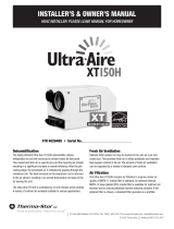
2. Utilice conductos flexibles de 1/4in para conectar un indicador de presión configurado para medir pulgadas
de columna de agua (a veces se muestra como “in. w.g.” o “in. H2O”) en los puertos de presión de entrada
y salida del ventilador. El indicador de presión debe contar con un rango lo más pequeño posible para
obtener una medición significativa: un rango de 1.0in de columna de agua debería ser suficiente. Conecte
el puerto superior o “+” del indicador de presión al puerto de presión de la salida del ventilador y el puerto
inferior o “-” del indicador al puerto de presión de la entrada del ventilador. Consulte la FIGURA13.
3. Modelo 8140NC: encienda el ventilador mediante el sistema de control instalado para el modelo 8140NC. Esto
se puede implementar al cambiar temporalmente la configuración del sistema de ventilación a 60 minutos/
hora o simplemente puede colocar un puente de conexión entre los terminales VENT del ventilador.
Modelo 8140: encienda el ventilador con el botón “Up” (Arriba) para aumentar la configuración del
sistema de ventilación a 60 min./hora.
4. Consulte la etiqueta que se encuentra en la tapa del ventilador, o la TABLA 3, para convertir la lectura de
presión a la medida de flujo de aire distribuido. Si la lectura de presión no corresponde con los valores
que figuran en la lista, utilice el valor más bajo o intercale entre los valores: CFM (pies cúbicos por minuto)
= valor menor + [(valor mayor – valor menor) * 10 * (lectura de presión – presión de menor valor)]. A
continuación se presenta un ejemplo:
a. La lectura de presión medida es 0.34in de columna de agua
b. La tabla 2 indica 205CFM a 0.3in de columna de agua y 175 a 0.4in de columna de agua.
c. Utilice 175CFM o intercale:
CFM = 175 + [(205-175) * 10 * (0.34-0.3)] = 175 + [(30) * 10 * (0.04)] = 175 + 12 = 187 CFM
La intercalación demostrará un flujo de aire distribuido más elevado, pero es necesario realizar un cálculo.
TABLA 3: FLUJO DE AIRE DISTRIBUIDO DE
ACUERDO CON LA PRESIÓN MEDIDA EN LOS
PUERTOS DE PRESIÓN DEL VENTILADOR
Presión medida
(in de columna de agua)
Flujo de aire distribuido
(pies cúbicos por minuto)
0.1 250
0.2 230
0.3 205
0.4 175
0.5 145
0.6 110
0.7 70
TABLA 2: MENÚ DEL MODO DE PRUEBA DEL MODELO 8140
Secuencia de prueba Descripción
MEASURED REQ’D CONT CFM
FAN
Después de 15 segundos, el ventilador del sistema de
HVAC se encenderá si se conectó y está configurado para
seguir este procedimiento. La pantalla mostrará FAN
(Ventilador) junto con tESt (Prueba).
MIN/
HR
CODE
Después de 45 segundos, el modo de prueba finalizará de
manera automática y la pantalla volverá a la pantalla de
funcionamiento.
ENTRADA
SALIDA
Baja
Alta
-
+
90-2354
FIGURA 13: MEDICIÓN DE LA PRESIÓN EN LOS
PUERTOS DE ENTRADA Y SALIDA DE PRESIÓN
8 Español
  • Page 1 1
  • Page 2 2
  • Page 3 3
  • Page 4 4
  • Page 5 5
  • Page 6 6
  • Page 7 7
  • Page 8 8
  • Page 9 9
  • Page 10 10
  • Page 11 11
  • Page 12 12
  • Page 13 13
  • Page 14 14
  • Page 15 15
  • Page 16 16
  • Page 17 17
  • Page 18 18
  • Page 19 19
  • Page 20 20
  • Page 21 21
  • Page 22 22
  • Page 23 23
  • Page 24 24

Aprilaire 8140 Owner's manual

Type
Owner's manual
This manual is also suitable for

Ask a question and I''ll find the answer in the document

Finding information in a document is now easier with AI

in other languages