Page is loading ...

www.omega.com
e-mail: [email protected]
User’s Guide
CN8500 Series
1/16 DIN Temperature and Process
Controllers

OMEGAnet
®
On-Line Service Internet e-mail
www.omega.com [email protected]
It is the policy of OMEGA to comply with all worldwide safety and EMC/EMI regulations that apply. OMEGA is constantly pursuing certification of
its products to the European New Approach Directives. OMEGA will add the CE mark to every appropriate device upon certification.
The information contained in this document is believed to be correct, but OMEGA Engineering, Inc. accepts no liability for any errors it contains, and
reserves the right to alter specifications without notice.
WARNING: These products are not designed for use in, and should not be used for, patient-connected applications.
Benelux:
Postbus 8034, 1180 LA Amstelveen
The Netherlands
TEL: +31 (0)20 6418405 FAX: +31 (0)20 6434643
Toll Free in Benelux: 0800 0993344
e-mail: [email protected]
Czech Republic:
Rude
´
arma
´
dy 1868, 733 01 Karvina
´
8
TEL: +420 (0)69 6311899 FAX: +420 (0)69 6311114
Toll Free in Czech Republic: 0800-1-66342
e-mail: [email protected]
France:
9, rue Denis Papin, 78190 Trappes
TEL: +33 (0)130 621 400 FAX: +33 (0)130 699 120
Toll Free in France: 0800-4-06342 e-mail: [email protected]
Servicing Europe:
USA and Canada:
Sales Service: 1-800-826-6342 / 1-800-TC-OMEGA
®
Customer Service: 1-800-622-2378 / 1-800-622-BEST
®
Engineering Service: 1-800-872-9436 / 1-800-USA-WHEN
®
TELEX:
996404 EASYLINK: 62968934 CABLE: OMEGA
USA: ISO 9001 Certified
One Omega Drive, P.O. Box 4047
Stamford CT 06907-0047
TEL: (203) 359-1660
FAX: (203) 359-7700
e-mail: [email protected]
Servicing North America:
For immediate technical or application assistance:
Mexico:
TEL: (001) 800-826-6342
FAX: (001) 203-359-7807
En Espan
~
ol: (001) 203-359-7803
e-mail: [email protected]
Germany/Austria:
Daimlerstrasse 26, D-75392
Deckenpfronn, Germany
TEL: +49 (0)7056 3017 FAX: +49 (0)7056 8540
Toll Free in Germany: 0800 TC-OMEGA
SM
e-mail: [email protected]
United Kingdom: ISO 9002 Certified
One Omega Drive
River Bend Technology Centre
Northbank, Irlam
Manchester M44 5EX United Kingdom
TEL: +44 (0)161 777 6611 FAX: +44 (0)161 777
6622
Toll Free in United Kingdom: 0800488488
e-mail: [email protected]
Canada:
976 Bergar
Laval (Quebec) H7L 5A1
TEL: (514) 856-6928
FAX: (514) 856-6886
e-mail: [email protected]

Table of
Contents
Installation
Mounting 2
Contact Identification 3
Sensor Input Connections 4
Power Wiring 5
Operation
Notes on Outputs 6
Notes on Alarms 13
Parameter Menu Organization
and Descriptions
16
Tuning Procedures 20
Options
Auto/Manual 26
Remote Setpoint Select 26
Recorder Output (PV retransmission) 28
Transducer Excitation 29
Digital Communications 30
Recalibration Procedure 37
Error Codes 37
Technical Specifications 38
Ordering Codes 42
Warranty Information 44

1
The OMEGA
®
CN8500 Temperature and
Process Controller features:
Omega Logic
TM
(allows selection of various cooling and
damping settings relative to single and multi-lag
processes and storage effects)
Single input, RTD, thermocouple, current and voltage
input models available
Voltage and current models scalable from -1999 to 9999
Non-volatile memory
NEMA 4X front panel
Adjustable hysteresis and heat-cool spread
User-selectable control modes (PID, PI, PD, and On/Off)
User-selectable ramp to setpoint
Auto-tuning, heat or cool
Dual output and alarm capability
RS-232 and RS-485 communications
Twin-branched double wipe contacts
Rugged molded housing with barriers and locking
terminals
100 mm depth behind panel
Wide range power supply: 100 to 250 Vac and 100 to
330 Vdc; 24 Vac/Vdc optional
Features

2
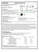
Figure 2. Case Dimensions
Prior to mounting the CN8500 Series in your panel, make sure
that the cutout opening is of the right size, 1.771" x 1.771"
(45 mm x 45 mm), and deburred to enable a smooth fit.
A minimum of 4" (100 mm) of depth behind the panel is required.
Figure 3. CN8500 Series Mechanical Components
Bezel
Case Clip
Grips
Rubber Gasket
Customer Panel
Installation
Figure 1. Recommended Panel Layout for Multiple
Controllers
Measurements between
centerlines of panel
cutouts
are minimum
recommended.
C
L
C
L
C
L
C
L
2.850" (72.4 mm)
2.150" (54.6 mm)
1.171" (45 mm)

3
Mounting
Notes on Wiring
Slide the mounting collar off and remove any wrapping
material from the instrument. (To ease removal of the collar,
gently pry up all three tabs on each side with a thin-blade screw-
driver.)
slide the mounting collar back onto the unit from behind the
panel. Press the tabs of the mounting collar into the ridges of
the case housing. The case should now be secure in the cutout.
If it can still be moved, reposition the mounting collar until the
unit is completely immobile within the panel.
If it is necessary to remove the CN8500 Series chassis from the
case housing, press the grips on each side of the front panel
bezel firmly until the tabs release. The chassis may then be
pulled out. To re-install, press both bezel grips simultaneously
and carefully push the chassis back into the case housing until
the tabs snap into place.
IMPORTANT: All electrical wiring connections should be made
only by trained personnel, and in strict accordance with the
National Electrical Code and local regulations.
Power and signal wires should always be kept separate and
input leads should never be placed in the same conduit as power
leads. We recommend separating connecting wires into bundles:
power, signal, alarms and outputs. These
bundles should then be routed through individual conduits.
Shielded sensor cables should always be terminated at panel
ground.
If additional RFI attenuation is required, noise suppression
devices such as an R.C. snubber at the external noise source
may be used.
Figure 4. Contact Identification

4
Sensor Input
Connections
Figure 5. Thermocouple Input Wiring
Make sure that you are using the
appropriate thermocouple and
extension wire. Connect the neg-
ative lead (generally colored red
in ISA-type thermocouples) to
contact #9; connect the positive
lead to contact #10. Extension wires must be the same
polarity as the thermocouple.
Figure 6. RTD Wiring
The CN8500 Series accepts
input from 2- or 3-wire, 100
ohm platinum resistance tem-
perature detectors (RTDs).
Connect 2-wire RTDs to con-
tacts #9 and #10, with a
jumper across contacts #8
and #9. Keep leads short and
use heavy gauge copper
extension wire, if necessary, to minimize lead resistance. For
long runs, 3-wire RTDs should be used.
Thermocouple circuit
resistance should not
exceed 100 ohms for
rated accuracy; errors
will occur at higher
resistance values. If
shielded thermocouple
wire is used, terminate
the shield only at panel
ground.
Use wire with a resis-
tance no greater than
10 ohms. An error of
0.2° F will result for
each additional 10
ohms of resistance
encountered. If shield-
ed RTD wire is used,
terminate the shield
only at panel ground.
Note: For 2 Wire RTD
Jumper 8 & 9

5
Power Wiring
Figure 7. Process and Linear Input Wiring
Voltage Inputs: Connect the
positive voltage input to con-
tact #10; the negative input to
contact #8.
mV/Current Inputs: Connect
the positive current input to
contact #10; the negative
input to #9.
The CN8500 Series power supply accepts 100 to 250 Vac,
100 to 330 Vdc, or 24 Vac/Vdc line power without any switch
settings or polarity considerations. All connections should be
made in accordance with the National Electrical Code and
local regulations, using only NEC Class 1 wiring for all power
terminals.
It is advisable, but not necessary, to fuse one leg of the
incoming power line, contact #11, with a 2AG, 0.5 amp
rated fuse. Be sure that only instrument power input is
fused — not power to the load.
100 - 250 Vac 50/60 HZ
100 - 330 Vdc (Auto Polarity)
24 Vac/Vdc (Auto Polarity)
Figure 8. Power
Wiring
Connection

6
Operation
Omega CN8500 Series Universal Controller
The CN8500 Series is a full-function, autotuning PID con-
troller, calibrated and pre-configured for your application
requirements, according to the ordering code specified, either
as a temperature or linear process controller.
Just a few easy steps are required before the instrument can
be placed into service. After completing the mounting and
wiring procedures as previously instructed, set your individ-
ual process parameter values by stepping through the
CN8500 Series’ setup menus, using the simple front-panel
keys as instructed. Then, initiate the autotuning sequence as
shown (or tune manually).
Notes on Outputs
When you ordered your CN8500 Series controller, a specific
output type was specified, designated as either “R1,R2”, “F1,
F2”, “DC1,DC2”, or “T1,T2”. If you ordered the dual-output
CN8502 model, you also had the option of configuring your
controller with either one or two output actions. Generally,
output 1 is a heat (reverse-acting) function and output 2 is a
cool (direct-acting) function. For best results, follow the
recommendations for setting cycle times for the output type
supplied with your controller. A brief description of output
types follows:
Output Type Description
R 5A/3A (120/240 Vac) relay, normally
open, used for switching resistive loads. If
relays or solenoids are to be driven, select
the “T” output.
F 4-20 mA, full output to load with 500 ohm
impedance max. (suppressed).
DC 20 Vdc pulsed output for solid-state relays.
T1 A @ 120/240 Vac , solid-state relay, zero
voltage-switched and optically isolated from
drive signal. Only resistive loads to
may be controlled directly. Larger loads
may be controlled using an external
contactor.

7
Operation
Mode Key Used to access Standby,
Tune, Run or Manual modes.
Lower Key Used to scroll down through
available parameter settings, decrease values
or change menu levels (Hold for fast-step
progression)
Raise Key Used to scroll up through available
parameter settings, increase values or change menu
levels (Hold for fast-step progression)
Parameter/Access Key Used to index through parameters
or to access Menu Levels
After mounting and wiring your
CN8500 Series controller, you are
ready to set the parameter values
required of your application. Take
a moment to familiarize yourself
with the unit’s front panel con-
trols and indicators.
Process Value
Displays measured
process temperature
in °F or °C or process
value in engineering
units
Setpoint Value
Displays programmed
setpoint temperature
in °F or °C or setpoint
value in engineering
units
Output 1
LED indication
of Heat cycle
(Output 1 action)
Output 2
LED indication
of Cool cycle
(Output 2 action)
Alarm 1
LED indication
of Alarm1 condition
Alarm 2
LED indication
of Alarm 2 condition
Function 1
LED indication of
Special Function 1
Function 2
LED indication of
Special Function 2
Figure 9. Front Panel Controls and Indicators

8
Operation
Power On
When power is first applied to the CN8500 controller, all LED
segments and indicators are momentarily illuminated. The
Process Value (PV) window then displays [ -At- ] or
[ -Ap- ] and the Setpoint Value (SV) window displays an ini-
tialization code, e.g., [ tf06 ]. The last two digits of this code
indicate the software revision supplied with your controller.
Please provide this revision number when contacting us
regarding your controller. Depending upon whether Setpoint
Target Time [ SP.tt ] is enabled, you may also see this symbol:
or . This means that the controller is ramping up or
down to setpoint according to its previously programmed
parameters. The default setpoint on initial power up is equal
to the process value. Before proceeding further, wait until the
display has stabilized and then use the Raise or Lower
keys to enter or adjust your desired Setpoint Value.
Parameter Menu Organization
Your CN8500 Series controller has five distinct menu levels.
This enables quick access to relevant parameters without the
need for scrolling through long menus. Menu “05” is used for

9
Operation
initial controller configuration and menus “02” and “03” are
used for setting or changing parameters. Menus “00” and
“01” are used when the controller is in regular unattended
operation and are not used for setting parameters. For safety
and security purposes, we recommend placing the con-
troller in menu level “00” or “01” when in regular opera-
tion; however, it is not required.
If you wish to “escape” from parameter selection within
these menus at any time, simply press the Mode key
once. A description of the menu hierarchy and a detailed list-
ing of menus and parameters begins on page 22.
Standby Mode
When the controller is placed in Standby Mode, outputs are
disabled; however, access is permitted to all menu levels and,
unless the controller is at Run menu levels “00” or “01”,
operating parameters may still be changed. Use this mode for
tuning the controller. To enter Standby Mode, press and hold
the Mode key for four seconds until the lower window
display flashes [ StbY ]. To exit Standby Mode from Menu
Levels “01” to “05”, press and hold the Mode key for four
seconds until the lower window display flashes [ tUnE ].
(If the Damping setting in menu “02” is [ OFF ], then [HEAt ]
or [ Cool ] will be displayed instead of [ tUnE ]. Press and
hold the Mode key for four more seconds until the lower
window returns to a steady display of Setpoint Value.
You cannot enter
Standby Mode from
menu level “00”.
Follow the instructions
for changing menu
levels to select another
level.

10
(This procedure will not affect tuning). Removing power to
the controller will also take the instrument out of Standby
Mode.
Accessing Menu Levels
To access menu levels from Standby Mode from menu
levels “02” to “05”, press the Parameter/Access key
once. From menu levels “00” and “01”, press and hold the
Parameter/Access key for approximately 11 seconds
until the lower window display alternates between [ Ac.Cd ]
and the menu level number last activated.
Changing or Displaying
Menu Levels
To change menu levels, access the menu level display as
instructed in the previous paragraph, then use the Raise
or Lower key to set the desired menu level number. To
display the current menu level setting in menu levels “02” to
“05”, from Standby or while adjusting/viewing parameters,
press the Parameter/Access key once. For menu levels
“00” and “01”, press and hold the Parameter/Access key
for approximately 11 seconds.
Operation

11
Because the CN8500
controller’s initial
configuration affects
other menu levels, it
is important to set all
required parameters in
this menu first before
accessing other
menu levels.
Operation
Menu Level Descriptions
Menu “05” (Configuration Setup)
This is the menu level used for specifying initial configuration
parameters before the controller is placed in Run mode.
After changing the access code to “05” as instructed in the
previous paragraph, press the Parameter/Access key to
step through the various control parameters. Available para-
meters will flash in the lower window display, alternating with
the current value for that parameter. To increase or decrease
the value, simply press the appropriate Raise or Lower
key, then press the key to step to the next parame-
ter. To exit the menu at any time, press the Mode key.
Note: When programming in menu level “05”, all outputs
are disabled; however, any active alarms will remain active
until the alarm condition is removed. New alarm conditions
will not be recognized.
Menu “04” (Communications and Calibration Setup)
This menu is used to set up the controller for digital
communications and for recalibrating the controller. If your
CN8500 Series controller was ordered with the digital com-
munications option, set these parameters next. To access this
menu level, follow the instructions previously given.

12
Operation
Menu “03” (Alarm, Timing and Limit Setup)
In this menu, alarms, cycle times, setpoint target time and
limits are established. After changing the access code to “03”,
press the Parameter/Access key to step through the vari-
ous parameters. To set or change parameter values, follow
the instructions given previously.
Menu “02” (Control)
Gain, Rate and Reset parameters are automatically set during
autotuning. However, they can be manually adjusted by the
operator. To return the controller to the Run mode, change
the menu level access code back to “00” or “01” as previous-
ly shown.
Menu “01” (Run — Limited Access Mode)
The only parameter that can be changed at this menu level is
the Setpoint Value, using the appropriate Raise or Lower
key. To set or change other parameters, the operator
must access another menu level by pressing and holding the
Parameter/Access key for 11 seconds.
Menu “00” (Run — “Key Lock” Lockout Mode)
This menu is automatically active when power is first applied.
Both display windows are illuminated; however, access is
denied to all parameters. To set or change parameters,
the operator must access another menu level as instructed
previously.

13
Operation
Notes on Alarms
Either [ OUT 1 ] or [OUT 2 ] in menu level “05” (but not both)
may be configured as an alarm [ ALr ] if your CN8502 con-
troller was ordered with an “R”, “DC” or “T” type of output
module. When one of the two available Outputs is configured
as an alarm, the other Output may be used for control .
When the controller is provided with the Dual Alarm option,
two independent alarms are automatically enabled for both
outputs. DO NOT USE THE [ ALr ] SETTINGS FOR [ OUT 1 ]
OR [ OUT 2 ]. Otherwise, follow the regular instructions for
configuring the Dual Alarms in menu level “05”.
The dual-output CN8502 offers a unique capability that pro-
vides for the activation of two software alarms (in addition to
the dual alarms) to monitor a total of four possible alarm con-
ditions. To enable these software alarms, set the [ OUT 1 ] and
[ OUT 2 ] parameter(s) in menu level “05” to on/off mode
[ Ht.O ], [ CL.O ] or [ On.F ]. Set the Setpoint Value to your
first alarm point. Switch to menu level “02” and set Spread
[ C.Spr ] or [ Spr.2 ] to the desired deviation value from the
first alarm point. Set [H.HYS] and [C.HYS] to 1. Then switch
to menu level “03” and set the desired values for the third and
fourth alarm points at [ ALr 1 ] and [ ALr 2 ], respectively.
Press the Mode key to resume operation.

14
Operation
Available Alarm Types [ A1.P.d. ] [ A2.P.d. ]
Selectable at menu level “05”, as either Process [ Pr ] or
Deviation [ dE ] and either high or low [ A1.HL ] or [ A2.HL ].
Process Alarm: Activates at preset value independent of
setpoint. “High” process alarm activates at and above alarm
setting. “Low” process alarm activates at and below alarm
setting.
Deviation Alarm: Activates at a preset deviation value from
setpoint. “High” or “Low” deviation alarm activates above or
below setpoint according to the preset deviation value.
Latching Alarms
The CN8500 Series’s alarms may also be configured as latch-
ing alarms by selecting “LAt” in the [ A1.O.P.] or [ A2.O.P.]
parameter selection at menu level “05”.
When a latching alarm
has been activated and
the alarm condition
has been removed, the
Mode key must be
pressed to unlatch the
alarm.

15
Figure 10. CN8500 Series Controller Menu Hierarchy
= temperature
controller only
= process
controller only
= temperature and
process controller
(All access denied)

16
Note: Menu parame-
ters shown in regular
typeface appear only
for temperature
input types; menu
parameters in bold-
face are for linear/
process input types.
Parameter
Descriptions
CN8500 Series Temperature/Process Controller
Menu “05”
Display Parameter Selection Code
SnSr Sensor type Thermocouple:
K c.A
JJ
Nn
Rr
Tt
SS
Platinel II PLII
RTD P (1 deg. resolution)
RTD (decimal range) d (0.1 deg. resolution)
FILt Digital Filtering 0.1-10.0
OUt1 Output 1 action Heat PID Ht.P
Heat On/Off Ht.O
Alarm ALr
OUt2 Output 2 action Cool PID CL.P
Cool On/Off CL.O
Alarm ALr
SN.00 Input Zero Level (0-20mA) U.Su (Unsuppressed)
(4-20mA) Su (Suppressed)
Dec.P Decimal Point 999, 99.9, 9.99
FILt Digital Filtering 0.1-10.0
OUt1 Output 1 action PID Pid
On/Off On.F
Alarm ALr
OUt2 Output 2 action PID Pid
On/Off ON.F
Alarm ALr
The Digital Filtering
setting [ FILt ] on the
CN8500 Series
controller allows the
operator to compen-
sate for noise which
may cause the last
digits of the PV dis-
play to become unsta-
ble. Sampling rate is
not affected. The set-
tings are time con-
stants, in seconds,
with 0.1 equivalent to
“no filtering.”

17
CoL.t* Cooling type Water H2o (non-linear output)
Normal nor (linear output)
A1.H.L. Alarm 1 select Enable Lo/HI
A1.P.d. Alarm 1 type Process/Deviation Pr/dE
A1.O.P. Alarm 1 output Off/Normal/Latching OFF/nor/LAt
A2.H.L. Alarm 2 select Enable Lo/HI
A2.P.d. Alarm 2 type Process/Deviation Pr/dE
A2.O.P. Alarm 2 output Off/Normal/Latching OFF/nor/LAt
Unlt Measurement units °F or °C F/C
* For water-cooled extruders, select H2o.
Menu “04”
Display Parameter Allowable Values
Id.no Device ID number 00 to 99
(remote communications)
bAUd Baud, parity and See chart below
data bit selection
CAL.L Calibration low Preset at factory
CAL.H Calibration high Preset at factory
Available Communications Settings
Display Description
Baud Rate Parity Data Bits Stop Bits
3.o.7 300 odd 7 2
6.o.7 600 odd 7 2
12.o.7 1200 odd 7 2
24.o.7 2400 odd 7 2
3.n.8 300 none 8 1
6.n.8 600 none 8 1
12.n.8 1200 none 8 1
24.n.8 2400 none 8 1
Parameter
Descriptions
/