Page is loading ...

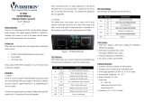
LED Indicators
LED Function State Status
Power indicatorOn
Fiber link
Link Loss Forwarding
Mode display
Mode display
Ethernet link
On
O
On
O
Blinking
On
O
Yellow
Green
O
On
O
On
O
Blinking
Converter has power.
Converter has no power.
The ber link is ok.
No link or the link is faulty.
Receiving data on the ber.
Link loss forwarding function enable.
Link loss forwarding function disable.
Force the LAN speed in 1000Base.
Force the LAN speed in 100Base.
Force the LAN speed in 10Base.
Full duplex mode.
Half duplex mode.
The UTP link is ok.
No link or the link is faulty.
Receiving data on Ethernet.
PWR
FX
LLF
Speed
Full
TX
Speed PWR
FULL LLF
TX FX
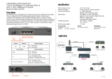
Installation Instructions
FIB1-1000ES 10/100/1000BASE-T
to 1000BASE-X
Managed Fiber Media Converter
Description
The Fiber Transceiver Converter Series gives you the option to choose from most popular ber cabling
connectors. The FIB1-1000ES provides you with two versions which support SFP socket with LC type
connectors for your ber optic cables and an RJ-45 connector for 10/100/1000Base-T twisted pair
cable connection. For the UTP side, auto-negotiation is default. These units will automatically tailor
themselves to 10/100/1000Base-T and both half-duplex or full-duplex signals depending on your
specic network needs. FX side is xed in full-duplex only. The Fiber Transceiver Converters give you
the freedom to extend your 1000Mbps cabling distance by allowing connectivity up to 0.5Km in
multi-mode or 80Km in single mode. Six LED indicators signal the power status of the converter,
UTP port, speed, Link/RX, status of duplex, ber port Link/RX and LLF (Link-Loss Forwarding).
V.: 1.1
Specifications
Standard
IEEE802.3 10Base-T, IEEE802.3u 100Base-TX, IEEE802.3ab 1000Base-T, IEEE802.3z 1000Base-X,
Gigabit Standards. Supports Full Duplex Ethernet mode (2000Mbps)
10/100/1000BASE-T RJ-45 Connectors
One RJ-45 connector is provided for connection to either MDI-X (To PC) or MDI (To HUB) equipment.
Utilizing Auto MDI/MDIX allows all UTP connections to be made using only a common straight-through
UTP cable.
568-A type 568-B typeRJ-45 Pin
1000BASE-T UTP Cable
Cable type: 1000Base-T; 4 pair , Cat. 5,
EIA/TIA-568, STP/UTP
Maximum cable distance: 100 meters
(328 feet)
Fiber Optic Connectors
SFP socket with LC is provided
Environment
Temperature : 0°C – 50°C
Humidity: 10-90% non condensing
Dimension
122.6mm x 85.6mm x 20mm
( W x D x H )
Power
AC adaptor +12V / 1A
5 Pair1-Tip Pair1-Tip
4 Pari1-Ring Pair1-Ring
3 Pair2-Tip Pair3-Tip
6 Pair2-Ring Pair3-Ring
1 Pair3-Tip Pair2-Tip
2 Pair3-Ring- Pair2-Ring
7 Pair4-Tip Pair4-Tip
8 Pair4-Ring Pair4-Ring
Fiber
Connections
Ethernet
Connections
LEDs
DC Jack
DIP
Switches
Jumpers Setting (on PCB)
LLF Function : On means enable, o means disable the function of LLF
( Link Loss Forwarding Function, detail please check Page2 )
ON OFF
DIP Switch Setting
Sw1~Sw3
Sw4
DIP
UTP Mode
Loop Back Test(LBT)
Function
UTP/NWAY
1000/Full
100/Full
100/Half
10/Full
10/Half
LBT o
LBT on
Status
O O O
On O O
O On O
O On On
On On O
On On On
O
On
State

V.: 1.1
Installation
Connect the ber interface cable to the FIB1-1000ES. Using a straight through or cross UTP cable, connect the
Ethernet connection to the appropriate RJ-45 jack. Set the "Duplex" switch (full and half ) according to the
specications of your equipments. Follow the connection examples below. Install the ber converter with the
DC power adapter provided (+12VDC) and connect the adapter to an AC outlet.
Connections
The following example illustrates the connection scheme when connecting from a 10/100/1000BASE-T port of
one HUB to a 10/100/1000BASE-T Network Interface Card (NIC) in a computer through the ber converter.
10/100/1000BASE-T UTP
straight connection
Fiber Cable 1000Base-X
Use RJ-45 jack
to HUB connection
10/100/1000BASE-T
UTP straight connection
10/100/1000BASE-T
UTP straight connection
Use RJ-45 jack to PC connection
Fiber Cable 1000Base-X
Use RJ-45 jack
to HUB connection
Link-Loss-Forwarding (LLF) Application Note
This media converter incorporates a Fiber Link Forwarding feature which allows indirect sensing of a Fiber Link
Loss via the 10/100/1000 Base-T UTP connection. Whenever the media converter detects a Link Loss condition on
the Receive ber (Fiber LNK OFF), it disables its UTP transmitter so that a Link Loss condition will be sensed on the
receive UTP port. (See the following gure) The link loss can then be sensed and reported by a Network
Management agent at the remote UTP port's host equipment. This feature has no eect on the media converter's
UTP LNK LED, which continues to function normally, independent of the state of the Fiber LNK LED and the UTP
transmitter. This feature is enabled by default on all the FIB1-1000 family media converters.
WARNING
This is a Class A product. In a domestic environment this product may cause radio interference in which case
the user may be required to take adequate measures.
CE NOTICE
Marking by the symbol CE indicates compliance of this equipment to the EMC directive of the European Community.
Such marking is indicative that this equipment meets or exceeds the following technical standards:
EN 55022:1994/A1:1995/A2:1997 Class A and EN61000-3-2:1995, EN61000-3-3:1995 and EN50082-1:1997
The following example illustrates the connection scheme when connecting from a 10/100/1000BASE-T port
of one HUB to a 1000BASE-SX/LX port of another HUB through the ber converter.
Figure: Explanation of Loop Back Test
This media converter incorporates a Fiber Loop-back Testing feature which allows the system to conrm that
the ber or Ethernet circuit loop is complete or not. The local-side unit will send out a detect message which
includes both command and test-pattern data to the remote-side unit and request for an answer. When the
remote-side unit receives the message, rst it will try to recognize the command, then it will deliver the received
test-pattern data back to the local-side unit. In this way, the circuit loop is complete. This feature is enabled by
the DIP switch#4 on the front panel. The get remote side status feature allows the system (both available for
FIB1 & FRM301 series application) to monitor the remote side status. First, the unit will send out a message which
includes a command to the remote side unit and request for an answer. When the remote side unit receives the
message, rst it will try to recognize the command, then it will delivery the remote side status back to the rack
mount unit. In this way, the rack mount unit can easily monitor every remote side unit. The remote side status
message include the ber side - link status and duplex status, the UTP side - link status, duplex status and speed
status, the power status, transmission status and ber (Tx side) failure status. The FIB1 series is compatible with
FRM301 series on this feature so you may test the whole application with FIB1 & FRM301.
Loop-Back Test (LBT)& Get CPE status Application Note :
( While this feature is operating the fiber side transmission will be halted )
Situation 1 : If the local side can not access to remote side under LBT is running then only the power LED will
still ash rapidly alone.
Fiber
FX
UTP
FX
UTP
Local Side
Remote Side
CPE status & Test-pattern Data
Command of Loop-back &
Get remote side status &
Test Pattern Data
Connecting to
HUB or PC
Connecting to
HUB or PC
1000BASE-X Fiber
Connection
Figure: Explanation of LLF
Switch or
PC
Link
Fail
TX
(OFF)
RX
RX
TX
TX
(OFF)
RX
RX
TX
TX
(OFF)
RX
RX
TX
TX
RX
RX
TX
TX
RX
RX
TX
Switch or
PC
Fiber
Link
Fail
Remote Fault
UTP
UTP
(OFF)
/